1
TM V.3.20A
Integrated Development Environment
User’s Manual
Rev. 1.00
May 01, 2003
REJ10J0018-0100Z
Microsoft, MS-DOS, Windows, and Windows NT are registered trademarks of Microsoft Corporation in the U.S. and other countries.
IBM and AT are registered trademarks of International Business Machines Corporation.
Intel and Pentium are registered trademarks of Intel Corporation.
Adobe, Acrobat, and Acrobat Reader are trademarks of Adobe Systems Incorporated.
All other brand and product names are trademarks, registered trademarks or service marks of their respective holders.
Keep safety first in your circuit designs!
z Renesas Technology Corporation and Renesas Solutions Corporation put the maximum effort into making semiconductor products
better and more reliable, but there is always the possibility that trouble may occur with them. Trouble with semiconductors may lead to
personal injury, fire or property damage. Remember to give due consideration to safety when making your circuit designs, with
appropriate measures such as (i) placement of substitutive, auxiliary circuits, (ii) use of nonflammable material or (iii) prevention
against any malfunction or mishap.
Notes regarding these materials
z These materials are intended as a reference to assist our customers in the selection of the Renesas Technology product best suited to
the customer's application; they do not convey any license under any intellectual property rights, or any other rights, belonging to
Renesas Technology Corporation, Renesas Solutions Corporation or a third party.
z Renesas Technology Corporation and Renesas Solutions Corporation assume no responsibility for any damage, or infringement of any
third-party's rights, originating in the use of any product data, diagrams, charts, programs, algorithms, or circuit application examples
contained in these materials.
z All information contained in these materials, including product data, diagrams, charts, programs and algorithms represents information
on products at the time of publication of these materials, and are subject to change by Renesas Technology Corporation and Renesas
Solutions Corporation without notice due to product improvements or other reasons. It is therefore recommended that customers
contact Renesas Technology Corporation, Renesas Solutions Corporation or an authorized Renesas Technology product distributor
for the latest product information before purchasing a product listed herein. The information described here may contain technical
inaccuracies or typographical errors. Renesas Technology Corporation and Renesas Solutions Corporation assume no responsibility
for any damage, liability, or other loss rising from these inaccuracies or errors. Please also pay attention to information published by
Renesas Technology Corporation and Renesas Solutions Corporation by various means, including the Renesas home page
(http://www.renesas.com).
z When using any or all of the information contained in these materials, including product data, diagrams, charts, programs, and
algorithms, please be sure to evaluate all information as a total system before making a final decision on the applicability of the
information and products. Renesas Technology Corporation and Renesas Solutions Corporation assume no responsibility for any
damage, liability or other loss resulting from the information contained herein.
z Renesas Technology semiconductors are not designed or manufactured for use in a device or system that is used under
circumstances in which human life is potentially at stake. Please contact Renesas Technology Corporation, Renesas Solutions
Corporation or an authorized Renesas Technology product distributor when considering the use of a product contained herein for any
specific purposes, such as apparatus or systems for transportation, vehicular, medical, aerospace, nuclear, or undersea repeater use.
z The prior written approval of Renesas Technology Corporation and Renesas Solutions Corporation is necessary to reprint or reproduce
in whole or in part these materials.
z If these products or technologies are subject to the Japanese export control restrictions, they must be exported under a license from
the Japanese government and cannot be imported into a country other than the approved destination. Any diversion or reexport
contrary to the export control laws and regulations of Japan and/or the country of destination is prohibited.
z Please contact Renesas Technology Corporation or Renesas Solutions Corporation for further details on these materials or the
products contained therein.
For inquiries about the contents of this document or product, fill in the text file the installer generates in the following directory and email
to your local distributor.
\SUPPORT\Product-name\SUPPORT.TXT
Renesas Tools Homepage
http://www.renesas.com/en/tools
Contents
1. Introduction
9
1.1 Operating Environment
9
1.2 Installation Method
10
1.2.1 Executing the Installer
1.2.2 Notes about TM Versions
1.2.3 Compiler and real time OS Combinations
1.2.4 Directories and Files Generated After Installation
1.3 Usage Precautions
10
10
10
11
12
1.3.1 Notes about File Names
12
1.3.2 Notes about Updating of Dependency Relations
12
1.3.3 Notes about Utility Software such as Virus Check Program
12
1.3.4 Notes about Network
12
1.3.5 Notes about Inspector
12
1.3.6 Makefile of library source.
13
1.3.7 The TM project of the former version was taken over.
13
1.3.8 Use real time OS
13
1.3.8.1 In the case of MR308 (for the M16C/80, M32C/80 series) ................................................ 13
1.3.8.2 In the case of MR30 (for M16C/60, 20 series) ................................................................... 13
1.3.8.3 In the case of MR79 (for 7900 series)................................................................................. 14
1.3.8.4 In the case of MR7700 (for 7700 series)............................................................................. 15
1.3.8.5 In the case of MR32R (for M32R series)............................................................................ 16
2. Overview
17
2.1 Integrated Development Environment
17
2.2 Concept of a Project
18
2.3 Roles of Each Tool Working under the TM
19
2.4 Directory Configuration
24
3. Quick Tour
26
3.1 Starting the TM and Registering the Editor Used
26
3.2 Creating a Project
28
3.3 Building a Project
37
4. Reference Manual
41
3
4.1 Project Bar
41
4.1.1 Overview
41
4.1.2 Buttons
42
4.1.3 Menus
43
4.1.4 Dialog Boxs
44
4.1.4.1 Tools Information Dialog Box............................................................................................ 44
4.1.4.2 Customize Dialog Box........................................................................................................ 47
4.1.4.3 Debug Tool Information Dialog Box.................................................................................. 50
4.1.4.4 Edit Tool Information Dialog Box...................................................................................... 51
4.1.4.5 Application Tool Information Dialog Box.......................................................................... 53
4.1.4.6 Current Directory Dialog Box ............................................................................................ 55
4.1.4.7 Environment Settings Dialog Box ...................................................................................... 56
4.1.4.8 Utility Execute Dialog Box................................................................................................. 57
4.1.4.9 Option Settings Dialog Box ................................................................................................ 58
4.2 Project Editor
59
4.2.1 Overview
59
4.2.2 Window Composition
59
4.2.2.1 Menus ................................................................................................................................. 60
4.2.2.2 Toolbar................................................................................................................................ 61
4.2.2.3 Status Bar............................................................................................................................ 61
4.2.2.4 Generation Procedure View ................................................................................................ 62
4.2.2.5 Item Information View ....................................................................................................... 62
4.2.2.6 Member View ..................................................................................................................... 62
4.2.2.7 Document View .................................................................................................................. 63
4.2.3 Method of Operation
64
4.2.3.1 Creating a New Project ....................................................................................................... 64
4.2.3.2 Opening a Project................................................................................................................ 67
4.2.3.3 Saving the Project by Overwriting...................................................................................... 67
4.2.3.4 Saving the Project by Specifying a Name........................................................................... 68
4.2.3.5 Outputting a Makefile ......................................................................................................... 68
4.2.3.6 Recently Used Files ............................................................................................................ 68
4.2.3.7 Exiting the Application ....................................................................................................... 69
4.2.3.8 Toolbar................................................................................................................................ 69
4.2.3.9 Status Bar............................................................................................................................ 69
4.2.3.10 Adding an Item ................................................................................................................. 69
4.2.3.11 Adding a File .................................................................................................................... 69
4.2.3.12 Command.......................................................................................................................... 70
4.2.3.13 Open.................................................................................................................................. 71
4.2.3.14 Properties .......................................................................................................................... 72
4.2.3.15 Partial Build ...................................................................................................................... 72
4.2.3.16 Delete................................................................................................................................ 72
4.2.3.17 Macro Browser ................................................................................................................. 73
4.2.3.18 Option Browser................................................................................................................. 74
4.2.3.19 Adding Member Information ............................................................................................ 75
4.2.3.20 Adding a Document .......................................................................................................... 76
4.2.3.21 Information ....................................................................................................................... 76
4.2.3.22 Scan All Dependencies ..................................................................................................... 77
4.2.3.23 Help................................................................................................................................... 77
4
4.2.3.24 Online Manual .................................................................................................................. 77
4.2.3.25 About Project Editor ......................................................................................................... 78
4.3 Builder
79
4.3.1 Overview
79
4.3.2 Builder Window
79
4.3.3 Functional Description
80
4.3.3.1 To Execute Build ................................................................................................................ 80
4.3.3.2 To Stop Building in the Middle .......................................................................................... 80
4.3.3.3 To Reexecute Previous Build.............................................................................................. 80
4.3.3.4 To Jump to a Location in Error or Warning........................................................................ 80
4.3.3.5 To Examine the Meaning of an Error or Warning .............................................................. 81
4.3.3.6 To Save Build Results......................................................................................................... 81
4.3.3.7 To Print Build Results......................................................................................................... 81
4.3.3.8 To Clear the Window.......................................................................................................... 81
4.3.3.9 To Search for an Error or Warning ..................................................................................... 82
4.3.3.10 To Change the Display Font ............................................................................................. 82
4.3.3.11 To Show Information........................................................................................................ 82
4.3.3.12 ........................................................................................................................................... 83
4.3.3.12 To Change Operation Environment .................................................................................. 83
4.4 Inspector
84
4.4.1 Overview
84
4.4.2 Inspector Window
84
4.4.3 Starting the Inspector
84
4.4.3.1 To Show Information List................................................................................................... 85
4.4.3.2 Narrow Down Search.......................................................................................................... 85
4.4.4 List Window
86
4.4.4.1 To Show Preview................................................................................................................ 86
4.4.4.2 To Open a Selected Entry with the Editor .......................................................................... 86
4.4.4.3 To Check a Check Box ....................................................................................................... 87
4.4.4.4 To Show Nesting of Function Trees ................................................................................... 87
4.4.4.5 To Rearrange Entries .......................................................................................................... 87
4.4.4.6 To Save a List ..................................................................................................................... 87
4.4.4.7 To Reanalyze after Loading the Latest Object.................................................................... 88
4.4.5 Preview Window
88
4.4.5.1 To Search for a String ......................................................................................................... 88
4.4.5.2 To Change the Display Font ............................................................................................... 88
4.4.5.3 To Change the Tab Width................................................................................................... 88
4.4.5.4 To Change the Display Color ............................................................................................. 88
4.4.6 Setting the Operating Environment
88
4.4.6.1 Action Tab .......................................................................................................................... 89
4.4.6.2 Preview Tab ........................................................................................................................ 89
5
Figures
Fig. 2-1 Example of Software Development Using the TM ................................................................. 17
Fig. 2-2 Project Name........................................................................................................................... 18
Fig. 2-3 Conceptual Diagram of the TM .............................................................................................. 19
Fig. 2-4 Project Bar .............................................................................................................................. 19
Fig. 2-5 Project Editor .......................................................................................................................... 20
Fig. 2-6 Builder..................................................................................................................................... 20
Fig. 2-7 Inspector.................................................................................................................................. 21
Fig. 2-8 Map Viewer ............................................................................................................................ 22
Fig. 2-9 STK Viewer ............................................................................................................................ 23
Fig. 3-1 Project Bar in Floating State ................................................................................................... 26
Fig. 3-2 Project Bar Pasted at The Top................................................................................................. 26
Fig. 3-3 Dialog Box for Registering an Editor ..................................................................................... 26
Fig. 3-4 Registering an Editor .............................................................................................................. 27
Fig. 3-5 [New Project] Button .............................................................................................................. 28
Fig. 3-6 New Project Wizard (Step 1) .................................................................................................. 28
Fig. 3-7 New Project Wizard (Step 2) .................................................................................................. 29
Fig. 3-8 New Project Wizard (Step Compiler) ..................................................................................... 29
Fig. 3-9 New Project Wizard (Step Finish) .......................................................................................... 30
Fig. 3-10 Project Editor Immediately After Project Creation ............................................................... 30
Fig. 3-11 Example of a Project ............................................................................................................. 31
Fig. 3-12 Adding a File......................................................................................................................... 32
Fig. 3-13 Selecting a Source File.......................................................................................................... 32
Fig. 3-14 View after Registering Source Files...................................................................................... 33
Fig. 3-15 Option Browser Start Button................................................................................................. 33
Fig. 3-16 Option Browser ..................................................................................................................... 33
Fig. 3-17 Option Setup Dialog Box ...................................................................................................... 34
Fig. 3-18 Creating a New Macro .......................................................................................................... 35
Fig. 3-19 Button for Registering Member Information ........................................................................ 35
Fig. 3-20 Registering Member Information.......................................................................................... 35
Fig. 3-21 Button for Adding Documents .............................................................................................. 36
Fig. 3-22 Displaying Registered Development Members and Documents ........................................... 36
Fig. 3-23 Save Button ........................................................................................................................... 37
Fig. 3-24 Build Button.......................................................................................................................... 37
Fig. 3-25 Dialog Box for Confirmation to Save ................................................................................... 37
Fig. 3-26 Error Display during Build Execution .................................................................................. 37
Fig. 3-27 Buttons for Using the Inspector ............................................................................................ 38
Fig. 3-28 Copying a String ................................................................................................................... 38
Fig. 3-29 Variable Reference Display Button....................................................................................... 38
Fig. 3-30 Showing Variable References ............................................................................................... 39
Fig. 3-31[Auto Read from Clipboard] Check Box ............................................................................... 39
Fig. 3-32 Showing Function References............................................................................................... 40
Fig. 3-33 Registering the Debugger...................................................................................................... 40
Fig. 3-34 Starting the Debugger ........................................................................................................... 40
Fig. 4-1 Tools Information Dialog Box ................................................................................................ 44
Fig. 4-2 DEBUG TOOL Tab ................................................................................................................ 44
6
Fig. 4-3 EDITOR TOOL tab ................................................................................................................ 45
Fig. 4-4 APPLICATION tab................................................................................................................. 46
Fig. 4-5 Customize Dialog Box ............................................................................................................ 47
Fig. 4-6 Setting tab ............................................................................................................................... 47
Fig. 4-7 Button tab................................................................................................................................ 48
Fig. 4-8 Inspector tab............................................................................................................................ 49
Fig. 4-9 Debug Tool Information Dialog Box ...................................................................................... 50
Fig. 4-10 Edit Tool Information Dialog Box ........................................................................................ 51
Fig. 4-11 Application Tool Information Dialog Box............................................................................ 53
Fig. 4-12 Current Directory Dialog Box............................................................................................... 55
Fig. 4-13 Environment Settings Dialog Box......................................................................................... 56
Fig. 4-14 Utility Execute Dialog Box................................................................................................... 57
Fig. 4-15 Option Settings Dialog Box .................................................................................................. 58
Fig. 4-16 Window Composition of the Project Editor .......................................................................... 59
Fig. 4-17 Status Bar .............................................................................................................................. 61
Fig. 4-18 Generation Procedure View .................................................................................................. 62
Fig. 4-19 Item Information View.......................................................................................................... 62
Fig. 4-20 Member View ....................................................................................................................... 62
Fig. 4-21 Document View .................................................................................................................... 63
Fig. 4-22 New Project - Step 1 ............................................................................................................. 64
Fig. 4-23 New Project - Step 2 ............................................................................................................. 64
Fig. 4-24 New Project - Step Compiler ................................................................................................ 65
Fig. 4-25 New Project - Step OS .......................................................................................................... 66
Fig. 4-26 New Project - Step Finish ..................................................................................................... 67
Fig. 4-27 Opening a Project.................................................................................................................. 67
Fig. 4-28 Saving the Project File .......................................................................................................... 68
Fig. 4-29 Outputting a Makefile ........................................................................................................... 68
Fig. 4-30 Confirming to save................................................................................................................ 69
Fig. 4-31 Adding an Item...................................................................................................................... 69
Fig. 4-32 Adding a File......................................................................................................................... 70
Fig. 4-33 Command Dialog Box .......................................................................................................... 70
Fig. 4-34 Setting a Command ............................................................................................................... 71
Fig. 4-35 Popup Menu for Dynamic Macro.......................................................................................... 71
Fig. 4-36 Item Properties ...................................................................................................................... 72
Fig. 4-37 Macro Browser...................................................................................................................... 73
Fig. 4-38 Adding a Macro .................................................................................................................... 73
Fig. 4-39 Option Browser ..................................................................................................................... 74
Fig. 4-40 Option Dialog Box ................................................................................................................ 75
Fig. 4-41 Adding Member Information ................................................................................................ 75
Fig. 4-42 Adding a Document .............................................................................................................. 76
Fig. 4-43 Project Properties (Target Tab) ............................................................................................. 76
Fig. 4-44 Project Properties (Tool Tab)................................................................................................ 77
Fig. 4-45 Showing Project Editor Version............................................................................................ 78
Fig. 4-46 Builder Window.................................................................................................................... 79
Fig. 4-47 Build Execution Buttons ....................................................................................................... 80
Fig. 4-48 Environment Dialog Box (Information Tab)......................................................................... 82
Fig. 4-49 Environment Dialog Box (Setting Tab) ................................................................................ 83
Fig. 4-50 Inspector Window ................................................................................................................. 84
7
Fig. 4-51 Inspector Startup Buttons...................................................................................................... 84
Fig. 4-52 Specify Detail Conditions Dialog Box.................................................................................. 85
Fig. 4-53 Rearrange Entries.................................................................................................................. 87
Fig. 4-54 [Update] button ..................................................................................................................... 88
Fig. 4-55 Environment Setup Dialog Box (Action Tab)....................................................................... 89
Fig. 4-56 Environment Setup Dialog Box (Preview Tab) .................................................................... 89
8
1. Introduction
1.1 Operating Environment
The following lists the host computers and OS versions on which TM has been verified to run.
Host Computer
OS Version
Handling instructions
IBM PC/AT or compatible
Microsoft Windows95
More than Internet Explorer4.0 is being installed.
Microsoft Windows98, 98SE
Microsoft WindowsMe
Microsoft WindowsNT 4.0
Microsoft Windows2000
To install TM, the user have to be granted the
administrator privilege.
Microsoft WindowsXP
Note that the TM does not run on Windows 3.1, Windows NT 3.51 or earlier, and EWS.
If your host computer or OS is not one of the above, please contact the manufacturer of your computer or OS to
confirm whether the software running under the above conditions will also work on the computer and OS that you now
have.
Please note that utility software such as a virus check program or performance acceleration tool may affect part of
the TM functions.
The table below lists the recommended hardware requirements.
Main Memory
Sufficient memory size in which OS operates normally (16 Mbytes or more)
Free disk capacity
20 Mbytes or more
CRT
1024 x 768 or higher is recommended
9
1.2 Installation Method
1.2.1 Executing the Installer
To install the TM, execute the installer included with it.
z Follow the messages displayed on the screen by the installer as you install the TM.
z The following lists the installer programs included with the package:
Language
Installer name
Japanese
\TM\W95J\SETUP
English
\TM\W95E\SETUP
1.2.2 Notes about TM Versions
When you are installing the TM over an existing version of TM, the installer displays a message to that effect. To
install TM V.3.20A on the same PC that has the version before V.2.xx already installed in it, specify a new directory to
install, and not the directory in which the earlier version is installed.
In cases where you have any cross tool which has had TM V.1xx bundled (e.g., NC30 WA V.3.00 Release 1) and is
installed along with the TM, if you install TM V.3.20A in the same directory without uninstalling TM V.1xx and then
uninstall the cross tool, you will become unable to use TM V.3.20A. In such a case, reinstall TM V.3.20A.
1.2.3 Compiler and real time OS Combinations
TM V.3.20A operates normally in one of the following combinations of compilers and real time OS. Use TM V.2.01
when you combine and use compiler or real time OS except for these.
TM
Compiler Product
Real time OS Product
V.3.20A
After NC30WA V.4.00 Release 1
After NC308WA V.3.00 Release 1
MR30 V.3.00 Release 1*
After MR30 V.3.20 Release 1
MR308 V.1.00 Release 1*
After NC79WA V.4.00 Release 1
After MR308 V.1.00 Release 2
MR79 V.1.10 Release 1*
After MR79 V.2.00 Release 1
After CC32R V.3.00 Release 1
After NC77WA V.5.20 Release 4
After MR32R V.3.30 Release 1
MR7700 V.3.20 Release 3*
After SRA74 V.4.10 Release 1
----------
When using any product marked by “*” and TM V.3.20A in combination
Once, Carry out “V2CVT.EXE” of the CD-ROM directory ([TM_V2]-[W95e]) which a TMV.2.01 installation
program is in through. This program is Wizard form in the same way as the installation program. When operation
is completed in accordance with the process, TM recognizes the product of the “*” mark.
10
1.2.4 Directories and Files Generated After Installation
When you finished installing the TM, the directories shown below are created in the directory in which you’ve
installed the TM, and the files listed below are copied into these directories.
Directory
File
bin
ProjectBar.exe (Project bar execution file)
ProjectEditor.exe (Project editor execution file)
Builder.exe (Builder execution file)
Inspector.exe (Inspector execution file)
Server.exe (Communication server execution file)
Make.exe (GNU Make execution file)
MtmSubp.exe (Builder subprogram)
BuilderPs.dll (Builder subprogram)
InsPs.dll (Inspector subprogram)
ProjectBarPs.dll (Project bar subprogram)
ProjectEditorPs.dll (Project editor subprogram)
ServerPs.dll (Communication server subprogram)
BuildErr.dll (Builder subprogram)
Ie_Inspect.dll (Inspector subprogram)
InsErr.dll (Inspector subprogram)
Insp_Inter.dll (Inspector subprogram)
Makefile.dll (Project editor subprogram)
PBResEn.dll (Project Bar resource file for English)
PEResEn.dll (Project editor resource file for English)
BldResEn.dll (Builder resource file for English)
InsResEn.dll (Inspector resource file for English)
Tme.hlp (TM help file)
Tme.cnt (TM help contents file)
ProjectBar.hlp (Project bar help file)
manual
Tmue.pdf (TM electronic manual)
Furthermore, the following files are copied into the directory where the OS is installed.
Directory
File
SYSTEM
Atl.dll (ATL support DLL)
11
1.3 Usage Precautions
1.3.1 Notes about File Names
The source program file names and work directory names are subject to the following limitations:
z No directory or file names that include kanji (2-byte characters) can be used.
z Only one instance of the period (.) can be used in a file name.
z No network path names can be used. Assign the directory you use to a drive name.
z No shortcuts can be used.
z No directory or file names that include a space character can be used.
Example: “My Documents” or “Program Files”
z The “...” notation cannot be used to specify two or more directories.
z File names exceeding 128 characters in length including path specification cannot be used.
1.3.2 Notes about Updating of Dependency Relations
In the analysis of file contents (detection of include files) performed while updating dependency relations, no
judgment is made with respect to whether #define statements are defined or not.
Also, for #if...#else...#endif statements, analysis is always made of the contents of source files between #if and #else
regardless of whether or not the condition statement holds true. Although there will be a case that you cannot find your
intended header files on the TM display, build (compile, assemble, and link) processing is performed exactly as written
in the source files.
1.3.3 Notes about Utility Software such as Virus Check Program
If build is executed while a specific version of utility software such as a virus check program or performance
accelerator is memory resident, a problem may occur that build execution results are not displayed on the builder. In
such a case, upgrade the utility software version or remove the utility software from memory while you use the TM.
1.3.4 Notes about Network
If you have the project or source files located on a network drive, make sure the computer on which you run the TM
and the computer on which files are placed are matched in time. Otherwise, build may not work correctly.
1.3.5 Notes about Inspector
In the project which used the compiler shown below, since an inspector has use restrictions, please be careful.
SRA74
NC77WA
CC32R
function definition
---
---
*
function reference
---
---
---
variable definition
---
---
*
variable reference
---
---
---
MAPViewer
---
---
*
STKViewer
---
---
---
Inspector
* : Use is possible.
--- : That an informational display is impossible or use is impossible.
12
1.3.6 Makefile of library source.
A project can’t make it normally when makefile.dos of the compiler accessory is read with TM. Carry out Make in
accordance with User’s Manual of the compiler from the Dos window when you change standard input and output
library.
1.3.7 The TM project of the former version was taken over.
Precondition: With NC30WA, NC308WA, and NC79WA in the combination
When the project made with TM of the former version is read, Inspector information output option “-finfo” isn’t added
automatically, and it can’t indicate information with Inspector. Carry out building after you add a “-finfo” option to
CFLAGS and AFLAGS to indicate Inspector information.
1.3.8 Use real time OS
Be careful because a compilation option and the designation of link library must be changed when you change the
next definition item of Configration file.
And, refer to the manual of the real time OS which copes with it for Configration file and the details of each definition
item.
1.3.8.1 In the case of MR308 (for the M16C/80, M32C/80 series)
1)
When 32 was specified in the message size.
Compilation option
: -Dfar_msg=1 is specified.
Link library
: mr308lm.lib and c308mrlm.lib are specified.
<Example>
system {
:
message_size = 32;
:
};
2)
When 16 was specified in the message size or designation was omitted.
Compilation option
: -Dfar_msg=1 isn’t specified.
Link library
: mr308.lib and c308mr.lib are specified.
<Exapmle>
system {
:
message_size = 16;
:
};
3)
4)
5)
When you put the source file of C besides “Working Directory” (.\).
Compilation option
: -I.
When you put the assembler source file besides “Working Directory” (.\).
Assembly option
: -I.
When you specify the output destination of the objects besides “Working Directory” (.\).
mr308tbl option
: The directory is specified at the output destination.
1.3.8.2 In the case of MR30 (for M16C/60, 20 series)
1)
When 32 was specified in the message size.
Compilation option
: -Dfar_msg=1 is specified.
Link library
: mr30lm.lib and c30mrlm.lib are specified.
<Expamle>
system {
:
message_size = 32;
:
};
13
2)
When 16 was specified in the message size or designation was omitted.
Compilation option
: -Dfar_msg=1 isn’t specified.
Link library
: mr30.lib and c30mr.lib are specified.
<Example>
system {
:
message_size = 16;
:
};
3)
4)
5)
When you put the source file of C besides “Working Directory” (.\).
Compilation option
: -I.
When you put the assembler source file besides “Working Directory” (.\).
Assembly option
: -I.
When you specify the output destination of the objects besides “Working Directory” (.\).
mkmrtbl option
: The directory is specified at the output destination.
1.3.8.3 In the case of MR79 (for 7900 series)
All version
1)
2)
3)
The option which you must surely specify
Assembly option
: -DC_inc=0
When you put the source file of C besides “Working Directory” (.\).
Compilation option
: -I.
When you put the assembler source file besides “Working Directory” (.\).
Assembly option
: -I.
When combining with the version before V.2.10 Release1
1)
24 was specified in the message size. When STANDARD was specified in the interruption prohibition model
or designation was omitted.
Compilation option
: -Dfar_msg=1 –fMJI is specified.
Link library
: mr79lm.lib and c79mrlm.lib are specified.
<Expamle>
system {
:
message_size = 24;
interrupt_model = STANDARD;
:
};
2)
When 24 was specified in the message size and SHORT was specified in the interruption prohibition model.
Compilation option
: -Dfar_msg=1 is specified, and –fMJI isn’t specified.
Link library
: mr79lmi.lib and c79mrlmi.lib are specified.
<Example>
system {
:
message_size = 24;
interrupt_model = SHORT;
:
};
14
3)
When 16 was specified in the message size or designation was omitted, and STANDARD was specified in
the interruption prohibition model or designation was omitted.
Compilation option
: -Dfar_msg=1 isn’t specified, and –fMJI is specified.
Link library
: mr79sm.lib and c79mrsm.lib are specified.
<Example>
system {
:
message_size = 16;
interrupt_model = STANDARD;
:
};
4)
When 16 was specified in the message size and or designation was omitted, and SHORT was specified in the
interruption prohibition.
Compilation option
: -Dfar_msg=1 isn’t specified, and –fMJI is specified.
Link library
: mr79smi.lib and c79mrsmi.lib are specified.
<Example>
system {
:
message_size = 16;
interrupt_model = SHORT;
:
};
5)
When a time-out function is used.
Compilation option
:
-Dtimeout=1 is specified.
:
-Dtimeout=1 isn’t specified.
<Example>
system {
:
timeout = YES;
:
};
6)
When a time-out function isn’t used.
Compilation option
<Example>
system {
:
timeout = NO;
:
};
1.3.8.4 In the case of MR7700 (for 7700 series)
1)
When you put the source file of C besides “Working Directory” (.\).
Compilation option
: -I.
2)
24 was specified in the message size. When STANDARD was specified in the interruption prohibition model
or designation was omitted.
Compilation option
: -Dfar_msg=1 is specified.
Link library
: mr77lm.lib and c77mrlm.lib are specified.
<Expamle>
system {
:
message_size = 24;
interrupt_model = STANDARD;
:
};
15
3)
When 24 was specified in the message size and SHORT was specified in the interruption prohibition model.
Compilation option
: -Dfar_msg=1 is specified.
Link library
: mr77lmi.lib and c77mrlm.lib are specified.
<Example>
system {
:
message_size = 24;
interrupt_model = SHORT;
:
};
4)
When 16 was specified in the message size or designation was omitted, and STANDARD was specified in
the interruption prohibition model or designation was omitted.
Compilation option
: -Dfar_msg=1 isn’t specified.
Link library
: mr77sm.lib and c77mrsm.lib are specified.
<Example>
system {
:
message_size = 16;
interrupt_model = STANDARD;
:
};
5)
When 16 was specified in the message size and or designation was omitted, and SHORT was specified in the
interruption prohibition.
Compilation option
: -Dfar_msg=1 isn’t specified.
Link library
: mr77sm.lib and c77mrsmi.lib are specified.
<Example>
system {
:
message_size = 16;
interrupt_model = SHORT;
:
};
1.3.8.5 In the case of MR32R (for M32R series)
1)
2)
When you put the source file of C besides “Working Directory” (.\).
Compilation option
: -I.
When you put the assembler source file besides “Working Directory” (.\).
Assembly option
: -I.
16
2. Overview
2.1 Integrated Development Environment
The Integrated Development Environment, TM, has been devised to increase the efficiency of software development
by integrating various tools such as the compiler, assembler, debugger, and editor into a common Graphical User
Interface (GUI). The TM has the following three primary functions:
z Manages the software development process using the concept of a project
z Provides a seamless environment as a common GUI for various tools
z Based on static program analysis, supports problem identification and reverse engineering needed during
large-scale software development
These functions together offer a greatly improved, comfortable development environment as compared when using
various tools individually.
Fig. 2-1 Example of Software Development Using the TM
17
2.2 Concept of a Project
The TM manages the software development process using the concept of a project. Following are managed as part of a
project by the TM:
z Procedural information necessary to generate the final object (normally the executable object)
z Information on source files associated with development
z Information on compile, etc. options
z Information on development members
z Information on development-related documents
You specify these items of information as you define a project. Furthermore, the TM reads out the following
information which was recorded to a file when the compiler, etc. were installed.
z Information on generation dependency relationship for the MCU family used
All these pieces of information are stored in a project file for management purposes. A project file actually consists of
the following two types of files:
z “Project name.TMK” file
z “Project name.TMI” file
The TMK file is prepared in the “makefile format” corresponding to the make command that is used standard in the
UNIXTM operating system, etc. This file contains the information necessary to generate the final object. On the other
hand, the TMI file contains information about the development members or documents that cannot be accommodated
by the makefile format TMK file. The project name1 always matches the project file names.2 The current project name
is displayed on the project bar when you start the TM.
Fig. 2-2 Project Name
1 Because a project name is used for file names, project names are subject to the same limitations as are file names. For example, any string that
contains kanji cannot be used for a project name.
2 Although when you created a new project, the final object name is created from the project name, the final object name and the project name do not
always have to coincide.
18
2.3 Roles of Each Tool Working under the TM
The TM works in close cooperation with many tools. Some of these tools have GUI as WindowsTM programs, and
others such as the C compiler or assembler or the GNU Make command operate at the back end of the TM.
The diagram below schematically shows the primary tools controlled by the TM.
Project Bar
Editor
Builder
Project
Map Viewer
Inspector
STK Viewer
Editor
Edit
Source File
Read
GNU Make
Edit
Makefile
Debugger
Read
Read
Absolute object file
Read
Read
Generate
C compiler, assembler
Fig. 2-3 Conceptual Diagram of the TM
Those included in TM V.3.20A
■
Project Bar
The project Bar plays the central role of the TM, helping to accomplish a linked startup of each tool. To start the TM,
you start the Project Bar. To exit the TM, you close the Project Bar.
Fig. 2-4 Project Bar
When you start the Project Bar, the TM creates a process named the “server” which exchanges tool linkage
information.3
3 Should a problem occur such as when the TM terminates abnormally, the “server” process may remain active without being closed. In such a case,
because the TM cannot be restarted under this condition, press the Ctrl + Alt + Del keys to bring up “Close Program” (Task Manager) and close the
server.
19
■
Project Editor
Use the Project Editor to define or alter the source files, compile options, or generation procedure included in a project.
The Project Editor works as an editor for the “makefile” handled by the GNU Make command.4
Fig. 2-5 Project Editor
■
Builder
The Builder invokes the GNU Make command to build a project based on the “makefile (TMK file)” created by the
Project Editor.
Fig. 2-6 Builder
4 When you added to or altered a project with the Project Editor, save the project to make your editing reflected in it. If you do not save the project
before operating on it, you are prompted to save.
20
■
Inspector
The Inspector provides a facility that based on the debug information included in the “absolute object file” generated
by build, analyzes the locations where functions and variables are defined or referenced. Unlike a simple string search,
the Inspector does the search based on the information embedded by the compiler.5 As a result, the following
advantages accrue:
z Comments and other non-compiled parts are not searched
z Can be searched separately for references and definitions
z Even when divided into multiple source files, the entire program can always be searched
Fig. 2-7 Inspector
■
GNU Make
The GNU Make command is an open-source software item compatible with the Make command available in the
UNIXTM operating system. It can be freely distributed according to GPL (GNU Public License). The GNU Make
command manages build operation based on the file dependency relations described in files known as the “makefile”
(e.g., a file .x30 is created from a file .r30).
5 The information on source file line numbers indicated by the Inspector is derived from syntactical analysis of the
source file by the compiler, etc. Therefore, the information is displayed at positions where syntactical analysis is
completed (same as displayed on the debugger). Because the grep command, etc., indicates the location of a searched
string, whereas the Inspector indicates separation in language syntax, there will be a difference between the two. For
example,
int func( char, <— Searched at this position by grep
int);
<— For the Inspector, this position is searched
21
Those included with the compiler package
■
Compiler and Assembler
TM V.3.20A currently supports the following compilers available from Renesas6:
z NC30WA V4.00 Release 1 or later
z NC308WA V3.00 Release 1 or later
z NC79WA V4.00 Release 1 or later
z CC32R V.3.00 Release1 or later
z NC77WA V.5.20 Release4 or later
z SRA74 V.4.10 Release1 or later
For the Inspector function to be used, add the “-finfo” option before compiling/assembling the source files.
■
Map Viewer
The Map Viewer allows you to examine memory mapping.
Fig. 2-8 Map Viewer
6 When you are using other Renesas compiler products or some version of compilers other than these versions, you cannot use TM V.3.20A. In such
a case, please use TM V2.01. Note that TM V.3.20A and TM V2.01 can coexist, so you can use either version as necessary.
22
■
STK Viewer
Use the STK Viewer to examine the amount of stack.7
Fig. 2-9 STK Viewer
Others
■
Editor
Any editor available on the market and you are accustomed to may be used after registering it to the TM.
■
Debugger
In addition to the PDxx series debuggers available from Renesas, any third-party debugger may be used after
registering it to the TM.
7 The STK Viewer is included in the package as a JavaTM application. For this reason, JavaTM 2 Runtime Environment (JRETM) is used. JRETM is
installed in the \install directory \BIN directory when installing the compiler.
23
2.4 Directory Configuration
This section describes how to configure the directory structure of the program when using the TM. When thinking of
the directory structure, it is important to understand the exact meaning of the “working directory” and the form in which
the source files registered to the project are entered “internally” in the system.
Working Directory
When generating a project, the Project Editor asks you to specify a working directory. This working directory has the
following three roles:
z Directory in which to store the project files
z Directory in which to store the objects generated as the result of compilation8
z Directory from which to start the compiler or debugger
When working with a project, this is the directory from which you start the compiler, etc., to which you output objects,
and in which you debug the program. (The source files, etc. do not always need to exist in locations below the working
director.) If you want to store the files output by the compiler in one directory, it may be a good idea to make that
directory the working directory.
Directory for source files, etc.
The directory in which the source files, etc. are registered by the Project Editor is as follows:
z Files located on the same drive as the working directory
These files are registered with a relative path from the working directory
z Files located on a different drive than the working directory
These files are registered with an absolute path
Open the TMK file with an editor to examine how the source files are registered in your system.
8 Prior to TM V2, we had the concept of an output directory. However, because this concept had difficulty processing the source line information and
other problems, we in V3 combined the working directory and output directory into one.
24
Example of a directory structure
With the above concept taken into account, a directory structure like the one shown below may be conceived.
C:\WORK
\ModelA
\ModelB
\SRCA
\SRCB
\COMMON
\HEAD
G:\COMMON
Working directory for model A
Working directory for model B
Source directory for model A
Source directory for model B
Common source directory for A and B
Common header file for A and B
Common source directory on a network
In this example, separate working directories, one for model A and one for model B, are prepared, in which a project
is worked on. The files placed on drive C are managed with a relative path from the working directory. All the
directories and files below the “\WORK” directory can be moved collectively to any desired location, providing that the
relative path relationship is maintained.
Prepared on drive G is the directory in which the common source files are stored when developing a project with
multiple people. Because the drive is different, this directory is managed with an absolute path. Therefore, we
recommend that this directory be assigned the same drive name on multiple computers.9
This is just an example. Any directory structure may be configured as desired, only if you know the meaning of the
working directory and how the files are registered.
9 Because network path names are not guaranteed for the TM to work properly, be sure to assign a drive for this common directory.
25
3. Quick Tour
3.1 Starting the TM and Registering the Editor Used
When the TM has been installed normally, the TM can be started by selecting [Start] -> [Programs] -> [RENESASTOOL] -> [TM V.3.xx] -> [TM] from the Start menu. When the TM starts up, the Project Bar appears.
Fig. 3-1 Project Bar in Floating State
When started for the first time, the Project Bar is in a “floating” state. Grasp this window and bring it to the top of the
screen, and you can have it located at the uppermost part of the desktop.
Fig. 3-2 Project Bar Pasted at The Top
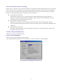
Next, register the editor you normally use.
Press the
button. A dialog box for registering an editor appears.
Fig. 3-3 Dialog Box for Registering an Editor
26
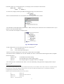
Choose [EDIT TOOL].
In the example below, the Peggy editor from Anchor Systems is registered.10
Fig. 3-4 Registering an Editor
The TM does not have any particular editor internally. The editor is a most frequently used tool for program
developers. To use an editor the program developers each know well and are accustomed to is we think the most
efficient. The TM allows any editor available on the market to be registered for use in it.11
10 The Peggy editor has its trial use version included in the “Compilers and Assemblers” CD-ROM from Renesas. Or it
can be purchased from the URL shown below.
http://www2.noritz.co.jp/anchor/
For details about this editor, contact Anchor Systems.
Note that the Peggy is for Japanese only.
11Most MS-DOSTM based editors do not work well. We recommend editors that run in WindowsTM.
27
3.2 Creating a Project
There are following three methods to create a project:
z Create a new project
z Read a project file of TM V2 or earlier version (MTM file) and convert it into TM V3 format project files
z Read an existing makefile and add additional information to create a project
Because the TM can read in existing makefiles, a project can easily be created even when you are conventionally not
using the TM.12
In this quick tour, we explain the method for creating a new project.
Creating a new project
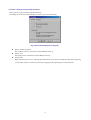
Press the [New Project] button on the Project Bar.
Fig. 3-5 [New Project] Button
A wizard to create a new project appears.
Fig. 3-6 New Project Wizard (Step 1)
12 Only the existing makefiles written with the GNU make compatible commands can be read into the TM. Those using NMAKE from Microsoft
cannot be read. Note also that when reading an existing makefile, the TM does a partial read assuming macros such as CFLAGS which are
customarily used for specific purposes. Therefore, if the makefile you read is contrary to general conventions, your expected results may not be
obtained.
28
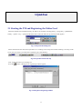
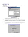
Choose the target chip and set a project name and the working directory.
Fig. 3-7 New Project Wizard (Step 2)
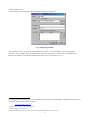
Next, choose the type of project.
Fig. 3-8 New Project Wizard (Step Compiler)
29
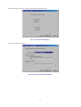
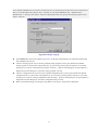
Choose [A default startup program is used.] for the startup program, and the startup program that comes standard with
the compiler is copied into the working directory.
Fig. 3-9 New Project Wizard (Step Finish)
Click [Finish] on the above dialog box, and the basic project information is created.
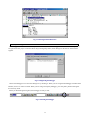
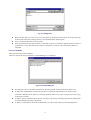
Registering files
When the TM has finished creating initial project information, the Project Editor window appears.
Fig. 3-10 Project Editor Immediately After Project Creation
The Project Editor works internally as an editor for the makefiles handled by the GNU make command. The project
view is a reflection of the concept of GNU make. To acquire a good command of the Project Editor, you need to
understand the basic concept of GNU make.
The basic structure of a makefile is as follows:
target : dependencies
command
This means that target depends on dependencies, and that to get target from dependencies, command must be
30
executed. If main.r30 is created from main.c, for example, write a statement as shown below.
main.r30 : main.c
nc30
-c
main.c
In such a case, display on the Project Editor should appear like the one shown below.
Show command information on a selected file (item) on the right side of the window.
The information will be displayed as shown above. What is meant by this is that main.r30 is created from main.c by an
operation “$(CC)$(CFLAGS) main.c.”
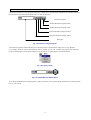
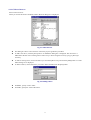
Now, we’ll show an example of a simple project.
Fig. 3-11 Example of a Project
In this example, there are two items at the top level: all and clean.13
all
Item to build a project
clean
Item to delete generated objects
These two are always displayed as essential items. (Other items can be added.)
The item all creates a “ModelA.x30” file. The “ModelA.x30” file is created from the following three files (it depends
on these three files):
ModelA.cmd
Command file used when linking
ncrt0.r30
Post-assemble object of the startup program
main.r30
Post-compile object of a program written in C language
The “main.r30” file is created from the “main.c” file. This relationship of file generation is displayed with a Project
Editor view.14
13 For projects using the real-time OS, you’ll have CFGEXECONTM at the top level, in addition to the two items, all and clean. CFGEXECONTM is
the item necessary to execute the configurator singly. However, since when you update the configuration file, it is automatically reconfigured,
reconfiguration by this item normally is unnecessary.
14 When written in makefile description, this becomes as follows:
all:
ModelA.x30
ModelA.x30:
ModelA.cmd ncrt0.r30 main.r30
ModelA.cmd:
ModelA.tmk
ncrt0.r30:
ncrt0.a30 sect30.inc
31
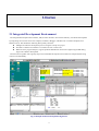
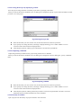
Now, we’ll try adding a file to the project. Choose the final object and then [Add file] from the right-click menu.
Fig. 3-12 Adding a File
Choose the file to add.
Fig. 3-13 Selecting a Source File
Before you can create the final object file “ModelA.x30,” you must have “main.r30” registered in your project. The
TM knows the dependency relationship between “.C” files and the “.R30”15. When you register a “.C” file by making
use of this, the file is registered reflecting the relationship between “.R30” and “.C” as judged by the TM.16
main.r30:
main.c
15 For NC30WA and NC308WA, the relocatable object files are identified by the extension “.R30.” For NC79WA, the relocatable object files are
identified by the extension “.R79.” Shown above is an example for NC30WA.
16 To update the dependency relations with the header files, use the [Scan All Dependencies] button. Unlike in TM V.2.01 or earlier, dependency
relations are not searched for by only registering a file.
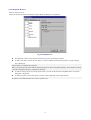
32
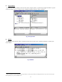
In this example, when you register “main.c,” the TM registers “main.r30” simultaneously with it, producing the
following display.
Fig. 3-14 View after Registering Source Files
When you register the source files, be sure to choose basically the final object (absolute object). The file may be
registered for other items. In such a case, consider the relationship between target and dependencies in the “makefile”
of the GNU make command as you work on file registration.
Choosing compile options
Use the “Option Browser” to choose or set compile (assemble) options.
Fig. 3-15 Option Browser Start Button
When the Option Browser starts up, a setup dialog box is displayed.
Fig. 3-16 Option Browser
33
Definitions of the following are entered by default for each option, respectively:
Compiler (nc30)
CFLAGS
Assembler (as30)
AFLAGS
Linker (ln30)
LFLAGS
Load module converter (lmc30)
LMCFLAGS
“CFLAGS” is a makefile macro, which defines the options used when compiling a program. Choose “CFLAGS” and
press the [Mod] button, and the dialog box shown below appears.
Fig. 3-17 Option Setup Dialog Box
Use this dialog box to choose the options you want to choose. Choose the type of option from Category and check the
options you need.17 Use [Other] when you set any option not found in the above check box or when you set a known
option directly.
17 The “-finfo” option is needed for the inspector function to be used. Do not change options such as “-c” which are associated with make control.
34
Or when you want to use different compile options for each file, choose “nc30” press the [New] button. This creates a
new macro named “CFLAGS1.” Choose options for this new macro and then the file for which you want the macro to
be applied. In this way, you can use different options for each file.
Choose the file for which to apply the macro
Choose the file for which
to apply the macro
Fig. 3-18 Creating a New Macro
Registering development members
To register the members participating in program development, use the [Add Member] button.
Fig. 3-19 Button for Registering Member Information
Fig. 3-20 Registering Member Information
When added in this way, the members are recorded to a project file and the development member information can be
managed as part of the project.
35
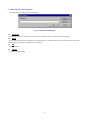
Registering documents
Specifications and other documents can be registered.18 To register documents, use the [Add Document] button.
Fig. 3-21 Button for Adding Documents
For example, when you register development members and documents, the registered information can be displayed on
a project view as shown below. Also, you can send a mail to a member or open a document by double-clicking on it.
Fig. 3-22 Displaying Registered Development Members and Documents
18 Registering a document means registering file information. Therefore, you are not registering the content of the actual document file by registering
a document.
36
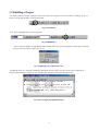
3.3 Building a Project
The Project Editor is an editor. Therefore, if the project has been changed, it must be saved before building. To save a
project, press the [Save] button on the Project Editor.
Fig. 3-23 Save Button
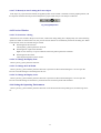
Next, press the [Build] button on the Project Bar.
Fig. 3-24 Build Button
This invokes the Builder, and the Builder starts building the project. If you attempted to build a project without
saving it, the Project Editor prompts you to save.
Fig. 3-25 Dialog Box for Confirmation to Save
The Builder starts up, compiling, assembling, and linking the source files. If an error occurs while compiling, for
example, double-click the location in error, and the editor starts up, showing the relevant location.
Fig. 3-26 Error Display during Build Execution
37
Analyzing with the Inspector
The Inspector allows for static program analysis by reading into it the final object “ModelA.x30” that has been built.
Use one of the Project Bar buttons shown below to start the Inspector.
Detail Setup button
Variable Reference Display button
Variable Definition Display button
Function Reference Display button
Function Definition Display button
String box
Fig. 3-27 Buttons for Using the Inspector
The Inspector performs functional analysis on the string which is entered in the String box by Copy & Paste.
For example, when you want to find locations where a variable system_code is used in the program, first enter that
string into the String box on the Project Bar by Copy & Paste or by typing directly from the keyboard.
Fig. 3-28 Copying a String
Fig. 3-29 Variable Reference Display Button
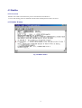
Press the [Variable Reference Display] button, and the Inspector starts up and outputs information on locations where
system_code is used.
38
Fig. 3-30 Showing Variable References
In this example, system_code is used in five locations. The variable can be previewed in the window located below by
selecting one instance of system_code. (The variable cannot be edited in this window. Double-click the variable location
you want to select, and the editor starts up.) The square boxes on the left side of the list are check boxes which can be
used in place of a memo.
The basic method to use the Inspector is by Copy & Paste. However, if you enable the function to capture a copied
string into the string storage box when you copy, you can omit Paste. To enable this function, press the [Customize]
button on the Project Bar and turn on the check box [Auto Read from Clipboard.]
Fig. 3-31[Auto Read from Clipboard] Check Box
If the string storage box does not contain any string, i.e., the box is blank, all information is displayed. For example,
when you press the [Function Reference Display] button while the box is blank, you will have a list of relationship of
function calls.
39
Fig. 3-32 Showing Function References
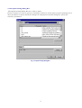
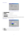
Starting the debugger
The Debugger can be started from the Project Bar. However, before the Debugger can be started in this way, it must
be registered to the project concerned. Press the [Tool Register] button, and a dialog box like the one shown below
appears.
Fig. 3-33 Registering the Debugger
Choose the Debugger to use from this dialog box by checking it. When you are using the PD Debugger available from
Renesas, choices to select are listed. When you are using a third-party debugger, press the [Add..] button and register
the necessary items.
When you finished registering here, the Debugger is ready to start.
Fig. 3-34 Starting the Debugger
40
4. Reference Manual
4.1 Project Bar
4.1.1 Overview
The Project Bar plays the central role of the TM. It accomplishes a linked invocation of each tool. To start the TM,
start the Project Bar. To exit the TM, close the Project Bar.
The Project Bar has the following functions:
z Start the Project Editor
z Start/register a debugger
z Start/register an editor
z Start/register applications
z Start the Inspector
z Start the STK Viewer
z Start the Map Viewer
41
4.1.2 Buttons
The following explains the function of each button on the Project Bar.
Button
Name
Function
Project Name Display
Box
Shows a project name.
New Project Button
Creates a new project. Click this button, and the Project Editor starts and a New
Project Wizard opens.
Project Open Button
Opens a project file. When you specify a project created by an earlier version of
the TM or makefile, the Project Editor starts and converts it into the project file
useful for this version of the TM.
Project Editor Start
Button
Starts the Project Editor. If the Project Editor is already active, the Project Editor is
displayed in front of all other windows.
Editor Start Button
Starts an editor. The editor to start must be registered and selected using the EDIT
TOOL tab of the Tools Information dialog box.
Tool Register Button
Opens the Tools Information dialog box from which you can register a debugger,
editor, or application.
Customize Button
Opens the Customize dialog box from which you can set up the Project Bar.
Inspect String Box
Specify a function or variable name to be displayed on the Inspector. Leave this
box blank, and all functions or variables are displayed. If Auto Read from
Clipboard is enabled using the Inspector tab of the Customize dialog box, the
string copied to the clipboard is automatically displayed here.
Function Definition
Display Button
Shows a list of function definitions on the Inspector.
Function Reference
Display Button
Shows a list of function references on the Inspector.
Variable Definition
Display Button
Shows a list of variable definitions on the Inspector.
Variable Reference
Display Button
Shows a list of variable references on the Inspector.
Detail Setup Button
Specify the contents to be displayed on the Inspector.
Stk Viewer Start Button
Starts the STK Viewer included with Renesas compilers. The STK Viewer
shows the amount of stack used.
Map Viewer Start
Button
Starts the Map Viewer included with Renesas compilers. The Map Viewer
graphically shows the condition of how the target program is mapped into
memory.
Partial Build Button
Builds an item selected from the Project Editor.
Build Button
Builds a project.
Rebuild Button
Rebuilds a project.
Debug Button
Starts a debugger. The debugger to start must be specified using the DEBUG
TOOL tab of the Tools Information dialog box. When you press this button
without specifying a debugger, the Tools Information dialog box opens up.
Home Page Display
Button
Shows the home page of the TM.
Help Button
Shows this help.
42
4.1.3 Menus
Shortcut menus are provided for the operations to be performed from the Project Bar. The shortcut menus are listed
below.
Menu Item
Function
Change Button Position (B)...
Set (C)
Always on Top
Auto Hide
Load Project
Changes settings to show, hide, or order of display of each button on the Project Bar.
Shows the Project Bar always in front of all other windows.
Automatically hides the Project Bar when it is docked to the edge of the screen.
Automatically loads the last loaded project when the Project Bar is activated.
Register Debugger (D)...
Registers a debugger.
Register Editor (E)...
Registers an editor.
Register Application (P)...
Registers an application.
Execute Utility(U)
Starts the utility included with Renesas compilers. The Execute Utility dialogbox opens when you select a
sub-menu. Please input a parameter of the utility in the dialog box.
Help (H)
Help for TM
Help for Compiler
Help for Assembler
Help for MRxx
Help for Debugger
Shows help for the TM.
Shows help for the compiler.
Shows help for the assembler.
Shows help for MRxx.
Shows help for PDxx or PDxxSIM.
Electronic Manual (M)
TM Manual
Compiler Manual
Assembler Manual
MRxx Manual
Debugger Manual
Shows a manual for the TM.
Shows a manual for the compiler.
Shows a manual for the assembler.
Shows a manual for MRxx.
Shows a manual for PDxx or PDxxSIM.
Show TM Home Page (W)
Shows the home page of the TM.
Project Bar Version (A)
Shows the version of the Project Bar.
Exit (X)
Exits the TM.
43
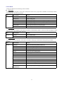
4.1.4 Dialog Boxs
4.1.4.1 Tools Information Dialog Box
The Tools Information dialog box is provided for registering a debugger, editor, or application.
Fig. 4-1 Tools Information Dialog Box
From this dialog box, the following can be set:
z To register a debugger...
z To register an editor...
z To register an application...
■
DEBUG TOOL
EDIT TOOL tab
APPLICATION
DEBUG TOOL tab
Use the DEBUG TOOL tab to register a debugger and select the debugger that starts up when you press the debug
button.
The debuggers available from Renesas are automatically added to the debugger list according to the project files
loaded. When you are using a third-party debugger, use the Add button to register it.
Fig. 4-2 DEBUG TOOL Tab
44
Debugger List
Shows registered debuggers. The user-registered debuggers are shown as “user:xxxx.” The debugger which has its
check box checked is the debugger used in the current project. The debugger to use can be changed by clicking the
check box of another debugger.
Add button
Adds a debugger. Clicking this button opens the Debug Tool Information dialog box.
Delete button
Deletes a selected debugger from the debugger list. However, this button can delete only the user-registered
debuggers.
Modify button
Modifies the registered content of a selected debugger on the debugger list. Clicking this button opens the Debug Tool
Information dialog box.
OK button
Reflects the contents you changed before closing the Tools Information dialog box.
Cancel button
Closes the Tools Information dialog box without reflecting the contents you changed.
■
EDITOR TOOL tab
Use the EDIT TOOL tab to register an editor and select the editor to use in the TM.
Fig. 4-3 EDITOR TOOL tab
Editor List
Shows registered editors. The editor used in the TM has its check box checked. The editor to use can be changed by
clicking the check box of another editor.
Add button
Adds an editor. Clicking this button opens the Edit Tool Information dialog box.
Delete button
Deletes a selected editor from the editor list. However, this button can delete only the user-registered editors.
Modify button
Modifies the registered content of a selected editor on the editor list. Clicking this button opens the Edit Tool
Information dialog box.
OK button
Reflects the contents you changed before closing the Tools Information dialog box.
Cancel button
Closes the Tools Information dialog box without reflecting the contents you changed.
45
■
APPLICATION tab
Use the APPLICATION tab to register an application and select the editor to use in the TM. A button for starting the
registered application is added to the Project Bar.
Fig. 4-4 APPLICATION tab
Application list
Shows registered applications.
Add button
Adds an application. Clicking this button opens the Application Information dialog box.
Delete button
Deletes a selected application from the application list.
Modify button
Modifies the registered content of a selected application on the application list. Clicking this button opens the
Application Information dialog box.
OK button
Reflects the contents you changed before closing the Tools Information dialog box.
Cancel button
Closes the Tools Information dialog box without reflecting the contents you changed.
46
4.1.4.2 Customize Dialog Box
The Customize dialog box is provided for changing various settings of the Project Bar.
Fig. 4-5 Customize Dialog Box
From this dialog box, the following can be set:
z To show the Project Bar...
z To change buttons...
z For Inspector-related settings...
■
Setting tab
Button tab
Inspector tab
Setting tab
Use the Setting tab to set the behavior of the Project Bar.
Fig. 4-6 Setting tab
z
z
z
Always on Top
Auto Hide
Load Project
Shows the Project Bar always in front of all other windows.
Automatically hides the Project Bar when it is docked to the edge of the screen.
Automatically loads the last loaded project when the Project Bar is activated.
47
■
Button tab
Use the Button tab to show or hide each button on the Project Bar and change the order in which they are displayed.
Fig. 4-7 Button tab
Button display view
Check the check box of a button, and the button is displayed. Uncheck a button, and the button goes out.
Upper button
Moves the selected button on the list view one place forward.
Lower button
Moves the selected button on the list view one place backward.
Add Application button
Adds an application.
Add Space button
Adds a space in front of the button selected on the list view.
Delete button
Deletes an added application.
48
■
Inspector tab
Use the Inspector tab to set Inspector-related settings.
Fig. 4-8 Inspector tab
Auto Read from Clipboard
Selects whether or not to automatically copy a copied string from the clipboard into the Inspector’s search string
display box.
49
4.1.4.3 Debug Tool Information Dialog Box
The Debug Tool Information dialog box is provided for registering a debugger.
Fig. 4-9 Debug Tool Information Dialog Box
■
Name (essential)
Enter a debugger name.
■
File Path (essential)
Enter a path to the debugger’s execution file. The file can also be selected by clicking the Browse button.
■
Current button
The current directory from which to start the debugger can be specified. By default, this is the directory where the
debugger’s execution file is stored. Clicking the Current button opens the Current Directory dialog box.
■
Etc(Version)
Use this text box to set version or other desired information.
■
Target Chip (essential)
Select the target chip to be operated on by the debugger.
■
Environment
This field shows environment variables used by the debugger.
■
Add button
Click this button when you want to add an environment variable. The Environment Settings dialog box opens.
■
Delete button
To delete any environment variable, select it from the list and click the Delete button.
■
Modify button
To modify any environment variable, select it from the list and click the Modify button. The Environment Settings
dialog box opens.
■
OK button
Click the OK button, and the contents you changed are reflected before closing the Tools Information dialog box.
■
Cancel button
Click the Cancel button, and the Tools Information dialog box is closed without reflecting the contents you changed.
50
4.1.4.4 Edit Tool Information Dialog Box
The Edit Tool Information dialog box is provided for registering an editor.
Fig. 4-10 Edit Tool Information Dialog Box
■
Name (essential)
Enter an editor name.
■
Default Editor check box
Check this check box, and the editor you are registering is registered as the default editor to be used by the TM. When
this button is unchecked, the editor is only registered.
■
File Path (essential)
Enter a path to the editor’s execution file. The file can also be selected by clicking the Browse button.
■
Current button
The current directory from which to start the editor can be specified. By default, this is the directory where the editor’s
execution file is stored. Clicking the Current button opens the Current Directory dialog box.
■
Etc(Version)
Use this text box to set version or other desired information.
■
Parameter
The TM has the function to show a specified line of the file you specify when starting the editor. Before this function
can be used, the method by which to specify a file and line must be registered to the TM.
To specify this, enter the startup option of the editor which you enter when starting the editor from the command
line. At this time, use %F and %L to specify the file name and line number, respectively. For example, if the editor
you use require specifying the following when you want to open the 166th line of the file “sample.c” in the editor
named MyEditor,
MyEditor.exe sample.c+166
enter %F+%L.
However, if the editor you are registering cannot be started by specifying a line number of the file, enter only the
method to specify a file. The method of specifying varies with each editor. For details, consult the user’s manual of your
editor.
51
■
Environment
This field shows environment variables used by the editor.
■
Add button
Click this button when you want to add an environment variable. The Environment Settings dialog box opens.
■
Delete button
To delete any environment variable, select it from the list and click the Delete button.
■
Modify button
To modify any environment variable, select it from the list and click the Modify button. The Environment Settings
dialog box opens.
■
OK button
Click the OK button, and the contents you changed are reflected before closing the Tools Information dialog box.
■
Cancel button
Click the Cancel button, and the Tools Information dialog box is closed without reflecting the contents you changed.
52
4.1.4.5 Application Tool Information Dialog Box
The Application Tool Information dialog box is provided for registering an application.
Fig. 4-11 Application Tool Information Dialog Box
■
Name (essential)
Enter an application name.
■
File Path (essential)
Enter a path to the application’s execution file. The file can also be selected by clicking the Browse button.
■
Current button
The current directory from which to start the application can be specified. By default, this is the directory where the
application’s execution file is stored. Clicking the Current button opens the Current Directory dialog box.
■
Etc(Version)
Use this text box to set version or other desired information.
■
Parameter
Enter the options or parameters the application uses. Write the following parameters, and the project file name, target
chip name, etc. can be passed to the application.
z %P
Project file name
z %W
Working directory
z %X
Target program name
z %T
Target chip name
■
Set parameter before executing
Turn this check box on, and a dialog box opens when the application starts up, allowing you to specify startup options
and parameters.
■
Environment
This field shows environment variables used by the application.
■
Add button
Click this button when you want to add an environment variable. The Environment Settings dialog box opens.
■
Delete button
To delete any environment variable, select it from the list and click the Delete button.
53
■
Modify button
To modify any environment variable, select it from the list and click the Modify button. The Environment Settings
dialog box opens.
■
OK button
Click the OK button, and the contents you changed are reflected before closing the Application Information dialog
box.
■
Cancel button
Click the Cancel button, and the Application Information dialog box is closed without reflecting the contents you
changed.
54
4.1.4.6 Current Directory Dialog Box
The Current Directory dialog box is provided for specifying the runtime directory.
Fig. 4-12 Current Directory Dialog Box
■
Directory that contains the execution file
The directory that contains the execution file of the tool to start is made the current directory.
■
Working Directory
The project’s working directory is made the current directory.
■
Other
Specify a directory that you want to be the current directory. This directory can also be specified by clicking the
Browse button.
■
■
Browse button
OK button
Click the OK button, and the contents you changed are reflected before closing the Current Directory dialog box.
■
Cancel button
Click the Cancel button, and the Current Directory dialog box is closed without reflecting the contents you changed.
55
4.1.4.7 Environment Settings Dialog Box
The Environment Settings dialog box is provided for specifying environment variables.
Fig. 4-13 Environment Settings Dialog Box
■
Name (essential)
Enter an environment variable name.
■
Value
Specify the value of the environment variable.
■
OK button
Click the OK button, and the contents you changed are reflected before closing the Environment Settings dialog box.
■
Cancel button
Click the Cancel button, and the Environment Settings dialog box is closed without reflecting the contents you
changed.
56
4.1.4.8 Utility Execute Dialog Box
The Utility Execute Dialog Box starts the utility.
Fig. 4-14 Utility Execute Dialog Box
■
Parameter
Specify the options for the utility. You can also use the Browse button to select the desired file path.
■
Detail
For the automatically TM recognized tools, the Detail button is available. When you click on this button, the Option
Settings dialog box appears, allowing you to set options.
■
OK
Starts the utility.
■
Cancel
Cancels starting the utility.
57
4.1.4.9 Option Settings Dialog Box
The Option Settings Dialog Box set a utility’s option.
Choose an option you want to specify by checking its check box. If the option requires specifying one or
more parameters, a Specify Parameter dialog box is displayed. From this dialog box, specify the
necessary parameters.
Fig. 4-15 Option Settings Dialog Box
58
4.2 Project Editor
4.2.1 Overview
The Project Editor is a window in which you can view and edit a project. Use the Project Editor to define or change
the source files or compile options or the project generation procedure included in the project. The Project Editor
functions as an editor for makefiles handled by the GNU Make command.
4.2.2 Window Composition
The diagram below shows the window composition of the Project Editor. The Project Editor is divided into a menu,
toolbar, status bar, generation procedure view, item information view, member view, and document view.
Fig. 4-16 Window Composition of the Project Editor
z
z
z
The Project Editor is started from the Project Bar to create a new project or open an existing project.
The primary commands of the Project Editor are assigned to its toolbar.
Only one project can be edited at a time. You cannot open multiple Project Editor windows at the same time.
59
4.2.2.1 Menus
The Project Editor has the following menus available.
■
File menu
The File menu has assigned to it the menu commands to load or save a project file or makefile, exit the Project Editor,
and perform other file-related operations.
Menu
Menu command
Function
File (F)
■
New Project (N)
Creates a new project
Open Project (O)
Opens an existing project
Save (S)
Saves the project being worked on to the current file (by overwriting)
Save As (A)
Saves the project being worked on to another file (by specifying a name)
Output Makefile (E)
Outputs the project being worked on to makefile
Recently used file
Opens a project from the history of recently used projects
Exit (X)
Closes the Project Editor
View menu
The View menu has assigned to it the menu commands to show/hide the toolbar or status bar and other display related
commands among the Project Editor functions.
Menu
Menu command
Function
View (V)
■
Toolbar (T)
Shows or hides the toolbar
Status Bar (S)
Shows or hides the status bar
Project menu
The Project menu has assigned to it the menu commands to edit project information among the Project Editor
functions.
Menu
Menu command
Function
Project (P)
Edit Item (E)
Edits the item selected on the generation procedure view
Add Item (I)
Adds an item to the generation procedure
Add File (F)
Adds a file to the generation procedure
Command (C)
Edits the generation procedure commands
Open (O)
Opens an item in its associated application
Property (P)
Shows the properties of an item
Partial Build (B)
Builds an item
Delete (D)
Deletes an item
Macro Browser (M)
Shows (edits) a macro
Option Browser (O)
Shows (edits) options
Add Member (A)
Adds member information to the project
Add Document (D)
Adds a document to the project
Information (I)
Shows information on the project being worked on
Scan All
Dependencies (S)
Updates the dependency relations of generation procedure
60
■
Help menu
The Help menu has assigned to it the menu commands to show the method for using the Project Editor or its version
information.
Menu
Menu command
Function
Help (H)
Help (H)
Shows help for the TM and help for tools used in the project
Online Manual (M)
Shows an electronic manual for the TM and an electronic manual for tools used in the
project
About Project Editor(A)
Shows the Project Editor’s version information
4.2.2.2 Toolbar
The toolbar has various buttons arranged on it that facilitate execution of frequently used commands.
Button
Button Name
Contents
New Project
Creates a new project
Open Project
Opens an existing project
Save
Saves the project being worked on to the current file (by overwriting)
Add Item
Adds an item to the generation procedure
Add File
Adds a file to the generation procedure
Command
Edits the generation procedure commands
Open
Opens an item in its associated application
Property
Shows properties of an item
Delete
Deletes an item
Macro Browser
Shows (edits) a macro
Option Browser
Shows (edits) options
Add Member
Adds member information to the project
Add Document
Adds a document to the project
Scan All Dependencies
Updates the dependency relationship of generation procedure
About Project Editor
Shows program information, version, and copyright
4.2.2.3 Status Bar
The status bar shows auxiliary information on how to use the TM. Shown below is an example of the status bar.
Fig. 4-17 Status Bar
61
4.2.2.4 Generation Procedure View
The generation procedure view shows information on project generation procedure (dependency relationship) in tree
form. Shown below is an outline diagram of the generation procedure view.
Fig. 4-18 Generation Procedure View
4.2.2.5 Item Information View
The item view shows detail information about the item selected on the generation procedure view. Shown below is an
outline diagram of the item information view.
Fig. 4-19 Item Information View
4.2.2.6 Member View
The member view shows information about the members added to the project. Shown below is an outline diagram of
the member view.
Fig. 4-20 Member View
62
4.2.2.7 Document View
The document view shows information about the documents. Shown below is an outline diagram of the document
view.
Fig. 4-21 Document View
63
4.2.3 Method of Operation
4.2.3.1 Creating a New Project
Create a new project.
When you choose this menu command, a New Project dialog box appears. The New Project dialog box is a wizardtype dialog box. From this dialog box, set the necessary entries sequentially.
Fig. 4-22 New Project - Step 1
z
z
z
z
From Target chip:, choose the target MCU for which you are creating a project.
For Project name:, enter the name of the new project you are creating. The name entered here constitutes the
final target program name and project file names.
For Working directory:, specify the directory in which to save the new project you are creating. If a nonexisting
directory is specified, the Project Editor creates a new directory. Press the [...] button, and a dialog box for
referencing folders appears. From this dialog box, choose a directory.
When you finished specifying all, click the [Next (N)] button. When settings are completed normally, New
Project Step 2 is displayed.
Fig. 4-23 New Project - Step 2
64
z
z
Here, choose the type of project.
When you finished selecting the type of project, click the [Next (N)] button. New Project - Step Compiler is
displayed.
Fig. 4-24 New Project - Step Compiler
z
z
z
From Compiler package:, choose the compiler you use. An already installed product is automatically displayed
in the [Compiler package] text box.
Choose a startup program. If you choose [A default startup program is used.], the compiler package’s default
startup program is copied to the working directory. If you choose [Custom], the file input box is activated,
allowing you to enter an existing startup program. Click the [...] button, and a dialog box for opening files is
displayed. From this dialog box, choose the startup program you want.
When you finished setting all, click the [Next (N)] button.
65
If you selected [ASM Project,] [C Project,] [Library Project,] or [Free Project] for the project type in New Project
Step 2, you are brought to New Project Step - Complete. If you selected [Realtime OS + ASM Project] or
[Realtime OS + C Project], New Project - Step OS is displayed. In this case, specify the startup program in New
Project - Step OS.
Fig. 4-25 New Project - Step OS
z
z
z
z
From Realtime OS:, choose the realtime OS you use. An already installed product is automatically displayed
in the Realtime OS text box.
Choose a startup program. If you choose [A default startup program is used.], the realtime OS’s default
startup program is copied to the working directory. If you choose [Custom], the file input box is activated,
allowing you to enter an existing startup program. Click the [...] button, and a dialog box for opening files is
displayed. From this dialog box, choose the startup program you want.
Choose a configuration file. If you choose [A default configuration file is used.], the realtime OS’s default
configuration file is copied to the working directory. If you choose [Custom], the file input box is activated,
allowing you to enter an existing configuration file. Click the [...] button, and a dialog box for opening files is
displayed. From this dialog box, choose the configuration file you want.
When you finished setting, click the [Next (N)] button. New Project - Step Finish is displayed.
66
Fig. 4-26 New Project - Step Finish
z
When you finished setting all entries on the New Project dialog box, the contents you’ve set are displayed
here. If the contents shown here are correct, click the [Finish (F)] button. If incorrect, click the [Back (B)]
button and reedit any entries that need to be corrected.
4.2.3.2 Opening a Project
Open an existing project file.
When you choose this menu command, a dialog box for opening files is displayed. From this dialog box, choose the
project file you want.
Fig. 4-27 Opening a Project
Choose a project file (any file name with the extension “.tmk”).
Click the [Open] button, and the project of the selected file opens.
Project files of TM V.2 or earlier versions (any file name with the extension “.mtm”) can be specified here.
Also, makefiles can be specified.
If a project file or makefile of TM V.2 or earlier version is specified, a project complement wizard is executed. Set
up following the instructions displayed.
z
z
z
4.2.3.3 Saving the Project by Overwriting
Save the project being worked on to the current project file by overwriting.
67
4.2.3.4 Saving the Project by Specifying a Name
Save the project being worked on to another project file by specifying a file name.
When you choose this menu command, a Save As dialog box is displayed. Specify any file name and folder in which
you want to save the project.
Fig. 4-28 Saving the Project File
z
z
z
Enter the file name you want. In this case, the extension does not need to be specified.
If you specify an existing file name, a message is displayed asking you to confirm whether or not to
overwrite. Follow the instructions displayed here.
Click the [Save] button, and the project information is saved to the specified file.
4.2.3.5 Outputting a Makefile
Output the generation procedure for the project being worked on to a makefile.
When you choose this menu command, a Save As dialog box is displayed. From this dialog box, specify a makefile
name.
Fig. 4-29 Outputting a Makefile
z
z
z
Enter the file name you want. In this case, the extension does not need to be specified.
If you specify an existing file name, a message is displayed asking you to confirm whether or not to
overwrite. Follow the instructions displayed here.
Click the [Save] button, and the generation procedure is saved to the specified file. The file is saved in a
format that can be executed with the GNU make command.
4.2.3.6 Recently Used Files
Open a project from the history of projects that have once been used.
68
A history of up to four projects is displayed.
4.2.3.7 Exiting the Application
Exit the Project Editor.
If the project being worked on has been edited, a message is displayed asking you to confirm whether or not to save.
Fig. 4-30 Confirming to save
z
z
z
To save the project before closing it, click the [Yes] button.
To close the project without saving it, click the [No] button.
To cancel closing the project, click the [Cancel] button.
4.2.3.8 Toolbar
Show or hide the toolbar.
The toolbar is displayed when this menu command is checked, and not displayed when this menu command is
unchecked.
4.2.3.9 Status Bar
Show or hide the status bar.
The status bar is displayed when this menu command is checked, and not displayed when this menu command is
unchecked.
4.2.3.10 Adding an Item
Add an item to the generation procedure.
When you choose this menu command, an Add Item dialog box is displayed. From this dialog box, specify the item
name you want to add.
Fig. 4-31 Adding an Item
z
z
For Item name:, specify the item name you want to add. It is added below the selected item on the generation
procedure view.
Check [Add at top], and the item is added at the level equivalent to that of all or clean, not below the selected
item on the generation procedure view.
4.2.3.11 Adding a File
Add a file to the generation procedure.
When you choose this menu command, an Open File dialog box is displayed. From this dialog box, specify the file
you want to add.
69
Fig. 4-32 Adding a File
z
z
z
Specify the file name you want. Two or more file names can be specified. (File names can be specified in up
to about 2,600 characters assuming that they are indicated with the absolute path.)
Even a nonexistent file name can be specified.
If the specified file has the same extension as that of the compiler or assembler’s default extension, the file is
recognized as a source file and has the compiler or assembler’s execution code automatically added as a
command.
4.2.3.12 Command
Edit a generation procedure command.
When you choose this menu command, a Command dialog box is displayed.
Fig. 4-33 Command Dialog Box
z
z
z
z
This dialog box shows command information for the item selected on the generation procedure view.
To add a new command line, click the [New] button. A Command Setup dialog box is displayed. The
command is added below the last line of existing commands. Move it up or down using the arrow keys [Up]
or [Down] as necessary.
To edit an existing command, choose the line you want to edit from [Command:] and click the [Mod] button.
A Command Setup dialog box is displayed.
To delete a command line, choose the command line you want to delete and then click the [Del] button.
70
Fig. 4-34 Setting a Command
z
z
z
For Command, enter a command.
The [Def macro ->] button adds a macro displayed by a macro browser to the command line.
The [Dyn macro ->] button adds a special macro defined by make to the command line. Click the button, and
a popup menu appears.
Fig. 4-35 Popup Menu for Dynamic Macro
4.2.3.13 Open
Open an item in its associated application.
After specifying a text file from items on the generation procedure view, choose this menu command. The text file is
opened using the editor which has been set with the Project Bar.
71
4.2.3.14 Properties
Show properties of an item.
Choose this menu command when an item on the generation procedure view is selected. A File Properties dialog box
is displayed.
Fig. 4-36 Item Properties
z
z
Properties are displayed only when an existing file is specified.
If necessary, edit Attributes.
4.2.3.15 Partial Build
Build an item selected on the generation procedure view.
4.2.3.16 Delete
Delete a selected item.
Delete an item from the project that is selected on the generation procedure view, member information view, or
document view.
72
4.2.3.17 Macro Browser
Show a macro browser.
When you choose this menu command, a Macro Browser dialog box is displayed.
Fig. 4-37 Macro Browser
z
z
z
z
This dialog box shows a list of macros used in the project’s generation procedure.
To add a new macro, click the [New] button. An Add Macro dialog box is displayed. The new macro is
added below the last line of existing macros. Move it up or down using the arrow keys [Up] or [Down] as
necessary.
To edit an existing macro, choose the macro you want from [Macro list:] and click the [Mod] button. An Add
Macro dialog box is displayed.
To delete a macro, choose the macro you want to delete and then click the [Del] button.
Fig. 4-38 Adding a Macro
z
z
For Macro:, specify a macro name.
For Value:, specify the value of the macro.
73
4.2.3.18 Option Browser
Show an option browser.
When you choose this menu command, an Option Browser dialog box is displayed.
Fig. 4-39 Option Browser
z
z
This dialog box shows a list of options used in the project’s generation procedure.
To add a new option, choose the tool name you want to add and click the [New] button. An Option dialog
box is displayed.
Option names are automatically assigned.
When you specify an option for each file, add the option first. Then, from [Selected files:] choose the file to which
you want to assign the option by checking its check box.
z To edit an existing option, choose the option name you want to edit and click the [Mod] button. An Option
dialog box is displayed.
z To delete an option, choose the option you want to delete and then click the [Del] button.
No options can be deleted unless two or more options exist.
74
Fig. 4-40 Option Dialog Box
z
Choose an option you want to specify by checking its check box. If the option requires specifying one or
more parameters, a Specify Parameter dialog box is displayed. From this dialog box, specify the necessary
parameters.
4.2.3.19 Adding Member Information
Add member information to the project.
When you choose this menu command, an Add Member dialog box is displayed.
Fig. 4-41 Adding Member Information
For Name:, specify the name of the information you want to add. Specify any entries other than the name as
necessary.
If information for Mail address: is specified, when you choose a member from the member information view and
then execute Open, mail creation by a mail transmit/receive application is automatically performed.
z
75
4.2.3.20 Adding a Document
Add a document file to the project.
When you choose this menu command, an Open File dialog box is displayed.
Fig. 4-42 Adding a Document
z Specify the document file you want to add to the project.
When you choose a registered document file and then execute Open, the file is executed by the application
associated with it by Windows.
4.2.3.21 Information
Show information on the project being worked on.
When you choose this menu command, project properties are displayed.
Fig. 4-43 Project Properties (Target Tab)
76
Fig. 4-44 Project Properties (Tool Tab)
z
z
This dialog box shows information on the project being worked on.
With the Tool tab, you can specify whether or not to use any tool, such as a load module converter, not just
normally used tools. To specify to use a tool, check its check box.
The checked tool is displayed on the option browser. Change options for the tool as necessary.
4.2.3.22 Scan All Dependencies
Update the dependency relationship in generation procedure.
This menu command updates the dependency relationship between the source files registered to the project. As a result,
the include files written in a source file are recognized and are automatically added to the project’s generation
procedure.
In TM V.2 or earlier versions, the dependency relationship was automatically updated when you added or edited
any source file. In TM V.3, however, this automatic updating of the dependency relationship is not supported. You
need to update the dependency relationship when necessary.
4.2.3.23 Help
Show help for the TM and help for the tools used in the project.
4.2.3.24 Online Manual
Show an electronic manual for the TM and an electronic manual for the tools used in the project.
77
4.2.3.25 About Project Editor
Show version information of the Project Editor.
When you choose this menu command, a Project Editor Version Information dialog box is displayed.
Fig. 4-45 Showing Project Editor Version
z
This dialog box allows you to verify the version of the Project Editor.
78
4.3 Builder
4.3.1 Overview
Builder is the window which does the practice of build and result indication.
An error and warning place are indicated with the mark, and help and text editor can start it.
4.3.2 Builder Window
Fig. 4-46 Builder Window
79
4.3.3 Functional Description
4.3.3.1 To Execute Build
The build operation can be executed in three ways: Build only the files selected with the Project Editor, build the
entire project, or rebuild the entire project. For details on how to run, refer to the description of the Project Bar in earlier
sections of this manual.
Build
Rebuild
Partial build
Fig. 4-47 Build Execution Buttons
4.3.3.2 To Stop Building in the Middle
z
z
Canceling from the menu bar
Choose [Action] - [Cancel Build] from the menu bar.
Canceling from the toolbar
Click the [Cancel] button on the toolbar.
4.3.3.3 To Reexecute Previous Build
z
z
Reexecuting from the menu bar
Choose [Action] - [Reexecute Build] from the menu bar.
Reexecuting from the toolbar
Click the [Reexecute] button on the toolbar.
4.3.3.4 To Jump to a Location in Error or Warning
When an error or warning occurs, a mark is shown at the beginning of the pertinent message in the build window.
Error
Internal error
Warning
If the displayed error message contains a file name and line number, the editor can be started by one of the following
operations, showing the relevant line in the source file or header file.
z Starting from the menu bar
While the cursor is located at the error or warning line, choose [Action] - [Open] from the menu bar.
z Starting from a right-click submenu
Right-click the error or warning line to open a submenu and choose [Open] from that submenu.
z Starting from the toolbar
Click the [Open] button on the toolbar.
80
4.3.3.5 To Examine the Meaning of an Error or Warning
Right-click the error or warning line to open a submenu and choose [Search for Help On] from that submenu. Help for
the cross tool is invoked, with the error message entered in the keyword text box. Choose a keyword string from the list.
Click the [View] button on the dialog box to verify the content of the error message.
4.3.3.6 To Save Build Results
The build results can be saved to a file in text format. A Save As dialog box is displayed by one of the following
operations.
z Saving from the menu bar
Choose [File] - [Save] from the menu bar.
z Saving from a right-click submenu
Right-click the error or warning line to open a submenu and choose [Save] from that submenu.
z Saving from the toolbar
Click the [Save] button on the toolbar.
In addition to saving the entire result, you also can copy the result to the clipboard one character at a time.
4.3.3.7 To Print Build Results
A Print dialog box is displayed by one of the following operations.
z Printing from the menu bar
Choose [File] - [Print] from the menu bar.
z Printing from a right-click submenu
Right-click the error or warning line to open a submenu and choose [Print] from that submenu.
z Printing from the toolbar
Click the [Print] button on the toolbar.
4.3.3.8 To Clear the Window
z
z
z
Clearing from the menu bar
Choose [Edit] - [Clear] from the menu bar.
Clearing from a right-click submenu
Right-click on the window to open a submenu and choose [Clear] from that submenu.
Clearing from the toolbar
Click the [Clear] button on the toolbar.
81
4.3.3.9 To Search for an Error or Warning
When an error or warning occurs, it can be searched for in the upward or downward direction from the cursor position.
You can search by error, by warning, or by error & warning. Furthermore, when the end of the file is reached during
search, you can start searching from the beginning of the file again, by setting up environment settings accordingly.
Execute one of the following operations to search for an error or warning.
z Searching from the menu bar
Choose [Edit] - [Search for Error] - [Search Upward] or [Search Downward], or [Edit] - [Search for
Warning] - [Search Upward] or [Search Downward], or [Edit] - [Search for Error & Warning] - [Search
Upward] or [Search Downward] from the menu bar.
z Searching from a right-click submenu
Right-click on the window to open a submenu and choose [Search error/warning upward] or [Search
error/warning downward] from that submenu. Errors and warnings cannot be searched for individually from
a submenu.
z Searching with a function key
The search command has function keys F5 through F7 assigned to it. For details about the contents of key
assignments, refer to the menu.
4.3.3.10 To Change the Display Font
Choose [View] - [Font] from the menu bar.
4.3.3.11 To Show Information
Choose [Action] - [Environment] from the menu bar.
Click the Information tab of the Environment dialog box to look up information on build operation.
Fig. 4-48 Environment Dialog Box (Information Tab)
82
4.3.3.12 To Change Operation Environment
Choose [Action] - [Environment] from the menu bar.
The Setting tab of the Environment dialog box allows you to set the following.
Fig. 4-49 Environment Dialog Box (Setting Tab)
z
z
z
Restore window condition
The window position is restored next time the Builder starts up.
Restore font
The display font is restored next time the Builder starts up.
Search mode
When searching for an error or warning, this mode allows you to choose to finish the search at the beginning
(or the end) of the file or restart the search after wrapping to the beginning (or the end) of the file.
83
4.4 Inspector
4.4.1 Overview
Inspector is the window which indicates function information and variable information. Information on the made
object is analyzed statically in the cause. Each information is classified with the tab, and indicated respectively in the
list.
A file name and a line number are outputted by each information, and it is possible that it opens with text editor.
4.4.2 Inspector Window
Menu bar
Toolbar
List window
Preview window
Fig. 4-50 Inspector Window
4.4.3 Starting the Inspector
Use the Project Bar to start the Inspector and display various information.
Specify function or variable name
Show function reference
Show variable reference
Detail settings of Inspector
Show function definition
Show variable definition
Fig. 4-51 Inspector Startup Buttons
84
4.4.3.1 To Show Information List
Click on either "Show function definition", "Show function reference", "Show variable definition ", " Show variable
reference " on the project bar. The indication tab of the button which it clicked on becomes active.
When a function or variable name are specified with [Insp:] box, a focusing tab is indicated, and only the information
which corresponded to the specified name is indicated. The wildcard (* or ?) can be used for this name.
4.4.3.2 Narrow Down Search
Click the [Detail Settings of Inspector] button on the Project Bar.
A Specify Detail Conditions dialog box is displayed. Specify various settings from this dialog box, and the Inspector
shows the information that matches specified conditions as a list in the narrow down tab.
Fig. 4-52 Specify Detail Conditions Dialog Box
■
Specifying the category and definition
For the Category and Definition entries, set the contents of analysis to be made.
Selectable entries
Condition
Function definition, function reference, function prototype, None
variable definition, variable reference
■
Specifying a function or variable name
Enter a function or variable name. The wildcard (* or ?) can be used for this name. If you do not want the function or
variable names to be case-sensitive, uncheck the check box for [Discriminate uppercase/lowercase].
85
■
Specifying the type
Selectable entries
Condition
All types, signed int, unsigned int, signed char, unsigned char, Other than function reference
signed short, unsigned short, signed long, unsigned long,
float, double,
void pointer, struct, union, enum, typedef, func, near pointer,
far pointer, array, void
■
■
■
■
Specifying the storage class
Selectable entries
Condition
Not specify, global, static, inline
Not specify, global, static in file, static in function
Function definition, function prototype
Variable definition, variable reference
Specifying the start address
Selectable entries
Condition
0x000000 - 0x0FFFFFF
Function definition, variable definition,
variable reference
Specifying the end address
Selectable entries
Condition
0x000000 - 0x0FFFFFF
Function definition, variable definition,
variable reference
Specifying a file
Specify a file name as a scope. This specification is accepted for all but function references. Write the file name in full
path. Only one file can be written.
■
Specifying a function
Specify a function name as the scope. This specification is accepted for only variable definitions and variable
references.
4.4.4 List Window
4.4.4.1 To Show Preview
Choose any entry with the mouse. If the file name and line number are correct, they are displayed in the preview
window.
4.4.4.2 To Open a Selected Entry with the Editor
If, while any entry is selected (while the preview window is displayed normally), the focus is located in the list
window, the editor can be started by one of the following operations performed, showing the relevant line.
z Starting from the menu bar
Choose [Action] - [Open] from the menu bar.
z Starting from a right-click submenu
Right-click the entry to open a submenu and choose [Open] from that submenu.
z Starting from the toolbar
Click the [Open] button on the toolbar.
z Starting from double-clicking
Double-click the entry.
86
4.4.4.3 To Check a Check Box
If, while a line mark area is displayed and any entry is selected, the focus is located in the list window, the check box
for an entry can be checked or unchecked by one of the following operations performed.
z Checking from the menu bar
Choose [Action] - [Set Line Select Mark] from the menu bar.
z Checking from a right-click submenu
Right-click the entry to open a submenu and choose [Set Line Select Mark] from that submenu.
z Checking directly
Check the check box directly.
z Checking automatically from the editor
Check [Auto Set Line Mark] on the Set Environment dialog box’s Action tab, and the check box is
automatically checked by the editor when it starts up. The check box cannot be unchecked by this method,
however.Choose [Action] - [Environment] to open the Set Environment dialog box.
4.4.4.4 To Show Nesting of Function Trees
To show nesting of function trees displayed for function references, click the [+] mark. To expand all trees below the
selected entry, choose [View] - [Show Tree Nest] from the menu bar.
4.4.4.5 To Rearrange Entries
In list view of all but function references, entries can be sorted in descending or ascending order by clicking the header
part of any entry.
Fig. 4-53 Rearrange Entries
4.4.4.6 To Save a List
The results of analysis can be saved to a tag file in text format or a file in CSV format. When the focus is located in
the list window, a Save As dialog box is displayed by one of the following operations.
z Saving from the menu bar
Choose [File] - [Save a List] from the menu bar.
z Saving from the toolbar
Click the [Save] button on the toolbar.
87
4.4.4.7 To Reanalyze after Loading the Latest Object
If the object or project has been altered, the [Update] button on the toolbar is enabled. Click the [Update] button, and
the Inspector loads the latest object and reanalyzes the project under the previous analysis conditions.
Fig. 4-54 [Update] button
4.4.5 Preview Window
4.4.5.1 To Search for a String
When the focus is located in the preview window, a Search for String dialog box is displayed by one of the following
operations. When no selected area exits, the previous search character is automatically entered in the dialog box. When
a selected area exists, the selected string is entered.
z Searching from the menu bar
Choose [Edit] - [Search] from the menu bar.
z Searching from a right-click submenu
Right-click on the entry to open a submenu and choose [Search] from that submenu.
z Searching from the toolbar
Click the [Search] button on the toolbar.
4.4.5.2 To Change the Display Font
Choose [View] - [Font] from the menu bar.
4.4.5.3 To Change the Tab Width
Choose [Action] - [Environment] from the menu bar to open the Set Environment dialog box. Click to open the
Preview tab of this dialog box and change the tab size.
4.4.5.4 To Change the Display Color
Choose [Action] - [Environment] from the menu bar to open the Set Environment dialog box. Click to open the
Preview tab of this dialog box and choose your desired colors for the keywords and comments.
4.4.6 Setting the Operating Environment
Choose [Action] - [Environment] from the menu bar. From the Environment setup dialog box, the following can be
set.
88
4.4.6.1 Action Tab
Fig. 4-55 Environment Setup Dialog Box (Action Tab)
■
Restore window condition
Restores the window position the next time the TM starts.
■
Restore font
Restores the display font the next time the TM starts.
■
Auto set line mark
Automatically checks line marks when opening the editor from the Inspector.
■
Automatic update
When using the Inspector from the Project Bar, if the object has been updated or the project has been altered, this
function automatically loads the object to perform analysis with updated contents. Unless this function is checked
(turned on), a dialog box is displayed for your confirmation.
4.4.6.2 Preview Tab
Fig. 4-56 Environment Setup Dialog Box (Preview Tab)
■
Tab size
Sets the preview window's display tab width. The tab size can be set in the range of 0 to 64.
■
Display color
Sets the colors in which to display the keywords and comments on the preview window.
89
MEMO
90
TM V.3.20A User’s Manual
Rev. 1.00
May 01, 2003
REJ10J0018-0100Z
COPYRIGHT ©2003 RENESAS TECHNOLOGY CORPORATION ALL RIGHTS RESERVED
AND RENESAS SOLUTIONS CORPORATION ALL RIGHTS RESERVED