1
SCADAPack 50
Installation
Connectors
Sensor connections
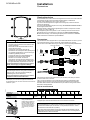
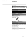
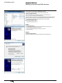
Digital Input or Counter
Digital inputs are filtered by an RC/Hysteresis device and are high impedance in
order to limit the power consumption. The reading voltage is approximately 3.3 V
and the reading current 3 μA. The connected contact should therefore be potentialfree and leakage-free. Dry contact and open-collector sensors are supported.
Wire between DI (1 to 4) and GND internal block
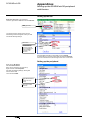
4-20 mA Analog Input
2-wire passive sensor block
Internal SCADAPack 50 block
+
+15V
–
AIn (n = 1 to 4)
Active sensor block
Internal SCADAPack 50 block
+
AIn (n = 1 to 4)
–
0V
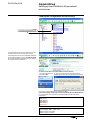
Voltage, Resistance, Platinium sensor analog inputs
Voltage sensor block
Internal SCADAPack 50 block
+
AIn (n = 1 to 4)
–
0V
Resistance, Platinium sensor block
Internal SCADAPack 50 block
Terminal 1 (*)
AIn (n = 1 to 4)
Terminal 2 (*)
0V
(*): any polarity
PT100 sensor – 3-wire:
GND
AIn+1
R
AIn
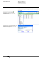
Modbus sensor
Modbus sensor block
Internal SCADAPack 50 block
Power +
+15V
Power –
GND
RS485 +
RS+
RS485 –
RS-
Due to the device’s optimized design for reduced energy consumption, the following
recommendations for the use of the Modbus link must be highlighted:
bb Use only shielded, twisted-pair cable.
bb The length of the cable connecting both SCADAPack 50 and the numerical sensor
should not exceed 3 metres (~10 ft.)
bb Perform a 3-wire connection: RS+, RS- and 0V (connect SCADAPack 50 0V
(GND) and Modbus sensor 0V reference)
bb The cable shield must be connected to the ground at both ends
bb In case of use in a larger network (connecting several devices), the RS485 bus
state of the art should be applied: an auxiliary power supply should be inserted in
order to offer proper RS 485 line polarization and the bus must be terminated by
end of line adaptation resistor at both ends.
NT00341-EN-03-SE-SCADAPack50-User-Manual
11