1
Regulation Manual
Manuel de régulation
Regelungshandbuch
Manuale di regolazione
Manual de regulación
PAC HT
12-6 ÷ 18-9
SOFTWARE
V5.1
English
12
Ü
17.9kW
Français
Deutsch
Italiano
Air-water Heat Pump
Pompe à Chaleur air-eau
Wärmepumpe Luft-Wasser
Pompa di Calore aria-acqua
Bomba de Calor aire-agua
UM PAC HT 01-N1
01-N1GB
Part number / Code / Teil Nummer / Codice / Código : 3990534
3990534GBSupersedes / Annule et
remplace / Annulliert
Supersedes
/ Annule et
und
remplace
ersetzt // Annulliert und ersetzt /
Annulla e sostituisce / Anula y sustituye : None / Aucun / Keine / Nessuno / Ninguno
Español
Regulation Manual
Manuel de régulation
Regelungshandbuch
Manuale di regolazione
Manual de regulación
CONTENTS
1. MANUAL USER GUIDE................................................................................................................................................ 3
1.1. ICONS.......................................................................................................................................................................................................... 3
1.2. MODIFIABLE PARAMETERS............................................................................................................................................................................. 3
2. MAIN FUNCTIONS..................................................................................................................................................... 4
2.1. SEMI-GRAPHIC DISPLAY................................................................................................................................................................................. 4
2.1.1. KEYPAD................................................................................................................................................................................................................................ 4
2.1.2. BACKLIGHTING.................................................................................................................................................................................................................... 4
2.1.3. MENUS................................................................................................................................................................................................................................ 5
2.1.4. ICONS................................................................................................................................................................................................................................. 5
2.1.5. STATUS POSSIBLITIES............................................................................................................................................................................................................ 6
2.2. ON/OFF, SUMMER/WINTER........................................................................................................................................................................... 7
2.2.1. ON/OFF.............................................................................................................................................................................................................................. 7
2.2.2. SUMMER/WINTER................................................................................................................................................................................................................. 7
2.2.3. PEAK ENERGY DAY CONFIGURATION.................................................................................................................................................................................. 8
2.3. HEAT CURVE, INTERACTION WITH THE ROOM TERMINAL............................................................................................................................ 10
2.3.1. GENERAL DESCRIPTION..................................................................................................................................................................................................... 10
2.3.2. HEAT CURVE IN RELATION TO OUTDOOR TEMPERATURE................................................................................................................................................... 10
2.3.3. HEAT CURVE AND ROOM TEMPERATURE MANAGEMENT.................................................................................................................................................... 11
2.3.4. MANUAL LEAVING WATER TEMPERATURE SETPOINT (CONSTANT HEAT CURVE)................................................................................................................... 15
2.4. RADIATORS / FLOOR HEATING CONFIGURATION....................................................................................................................................... 15
2.4.1. CHANGING FROM RADIATORS TO FLOOR HEATING CONFIGURATION............................................................................................................................. 15
2.4.2. LEAVING WATER TEMPERATURE LIMITATION........................................................................................................................................................................ 16
2.5. COMPRESSOR MANAGEMENT.................................................................................................................................................................... 17
2.5.1. TECHNICAL OPERATING LIMITS.......................................................................................................................................................................................... 17
2.5.2. CHOICE OF COMPRESSOR IN RELATION TO THE HOUSE'S THERMAL LOAD (HEATING MODE)........................................................................................... 18
2.5.3. MANUAL COMPRESSOR MANAGEMENT............................................................................................................................................................................. 19
2.6. DOMESTIC HOT WATER.............................................................................................................................................................................. 21
2.6.1. DHW FUNCTION ACTIVATION........................................................................................................................................................................................... 21
2.6.2. DHW DEMAND AND ROOM TEMPERATURE MANAGEMENT................................................................................................................................................ 21
2.6.3. COMFORT/ECO TEMPERATURE SETPOINTS (SCHEDULING)................................................................................................................................................ 22
2.6.4. "QUICK HEAT-UP" FUNCTION............................................................................................................................................................................................. 28
2.6.5. COMPRESSOR MANAGEMENT........................................................................................................................................................................................... 28
2.6.6. ADDITIONAL ELECTRIC HEATER MANAGEMENT ................................................................................................................................................................. 29
2.6.7. LEGIONNAIRES' DISEASE PROTECTION FUNCTION............................................................................................................................................................ 30
2.6.8. HEATING D DHW CHANGEOVER....................................................................................................................................................................................... 31
2.7. INLINE ELECTRIC HEATER............................................................................................................................................................................. 32
2.7.1. ELECTRIC HEATER FUNCTION ACTIVATION ....................................................................................................................................................................... 32
2.7.2. EMERGENCY AND BACK-UP + EMERGENCY COMMON FUNCTIONS................................................................................................................................ 32
2.8. BOILER RELIEF............................................................................................................................................................................................. 37
2.8.1. BOILER RELIEF FUNCTION ACTIVATION.............................................................................................................................................................................. 37
2.8.2. BOILER RELIEF MANAGEMENT............................................................................................................................................................................................ 37
3. OTHER FUNCTIONS................................................................................................................................................. 41
3.1. WATER PUMP MANAGEMENT...................................................................................................................................................................... 41
3.1.1. EXTERNAL........................................................................................................................................................................................................................... 41
3.1.2. PUMP ENTIRELY MANAGED BY THE PAC HT......................................................................................................................................................................... 41
3.2. ANTI-FREEZE FUNCTION............................................................................................................................................................................. 43
3.2.1. WATER PUMP..................................................................................................................................................................................................................... 43
3.2.2. PLATE HEAT EXCHANGER PROTECTION.............................................................................................................................................................................. 43
3.2.3. COMPRESSOR MANAGEMENT........................................................................................................................................................................................... 43
3.3. ALARM LOG................................................................................................................................................................................................ 44
3.3.1. H1..................................................................................................................................................................................................................................... 44
3.3.2. H2..................................................................................................................................................................................................................................... 45
3.4. DE-ICING.................................................................................................................................................................................................... 45
3.4.1. DE-ICING MANAGEMENT BY TIME..................................................................................................................................................................................... 45
3.4.2. ANTICIPATED DE-ICING...................................................................................................................................................................................................... 47
3.4.3. DE-ICING SEQUENCE........................................................................................................................................................................................................ 48
3.4.4. EXAMPLE OF DE-ICING...................................................................................................................................................................................................... 49
3.4.5. MANUAL DE-ICING............................................................................................................................................................................................................ 50
3.5. VIEWING ROOM TERMINAL PARAMETERS.................................................................................................................................................... 50
3.5.1. SCREEN TH1...................................................................................................................................................................................................................... 51
3.5.2. SCREEN TH2...................................................................................................................................................................................................................... 51
3.5.3. SCREEN TH3...................................................................................................................................................................................................................... 51
3.5.4. SCREEN TH4...................................................................................................................................................................................................................... 51
3.5.5. SCREEN TH0...................................................................................................................................................................................................................... 51
3.6. VIEWING INPUT/OUTPUTS.......................................................................................................................................................................... 52
3.6.1. SENSOR INPUTS................................................................................................................................................................................................................. 52
3.6.2. DIGITAL INPUTS.................................................................................................................................................................................................................. 52
3.6.3. DIGITAL OUTPUTS.............................................................................................................................................................................................................. 52
3.7. MANUAL OUPUTS....................................................................................................................................................................................... 53
3.7.1. MANUAL OUTPUT FUNCTION ACTIVATION........................................................................................................................................................................ 53
3.7.2. WATER PUMP..................................................................................................................................................................................................................... 53
3.7.3. VALVES............................................................................................................................................................................................................................... 53
3.7.4. COMPRESSOR CRANKCASE HEATERS................................................................................................................................................................................. 53
3.7.5. FANS.................................................................................................................................................................................................................................. 54
3.7.6. DOMESTIC HOT WATER (DHW).......................................................................................................................................................................................... 54
3.7.7. ELECTRIC HEATER............................................................................................................................................................................................................... 54
3.7.8. BOILER RELIEF.................................................................................................................................................................................................................... 54
3.8. OUTDOOR TEMPERATURE / REMOTE SENSOR MANAGEMENT..................................................................................................................... 55
3.8.1. ROOM HEATING MODE..................................................................................................................................................................................................... 55
3.8.2. DHW MODE...................................................................................................................................................................................................................... 55
3.8.3. NO NEED FROM ROOM TEMPERATURE OR IN SUMMER MODE.......................................................................................................................................... 55
3.8.4. DE-ICING.......................................................................................................................................................................................................................... 55
3.8.5. REMOTE OUTDOOR SENSOR............................................................................................................................................................................................ 56
3.9. OPERATING TIME, NUMBER OF STARTS....................................................................................................................................................... 56
3.9.1. OPERATING TIME............................................................................................................................................................................................................... 56
3.9.2. NUMBER OF STARTS........................................................................................................................................................................................................... 57
3.10. COMPRESSOR CRANKCASE HEATER MANAGEMENT.................................................................................................................................. 57
3.11. NEW INSTALLATION PASSWORD................................................................................................................................................................ 58
4. ALARM LIST AVAILABLE ON THE PAC HT DISPLAY.................................................................................................... 59
5. MENU DESCRIPTION................................................................................................................................................ 63
2
IN ORDER TO ENSURE THAT APPLIANCE SAFETY PROTECTION SYSTEMS
REMAIN ACTIVE (COMPRESSOR SUMP HEATER, ANTI-FREEZING
PROTECTION, CIRCULATION PUMP ANTI-SEIZING PROTECTION), WE
STRONGLY ADVISE AGAINST SWITCHINGOFF THE POWER SUPPLY TO
THE PAC HT WHEN IT IS NOT IN USE FOR HEATING.
1. MANUAL USER GUIDE
The purpose of this manual is to explain the various functions and possibilities offered by the PAC HT
regulation system. The manual also provides a detailed description of all the parameters accessible
via the graphic display integrated in the appliance, as well as a few parameters to be set at the
time of start-up.
1.1. ICONS
Several different icons are present throughout the document:
WARNING: Warns of a risk to proper operation of the PAC HT, of a strong recommendation
associated with occupant comfort or energy savings, or of important points of which a good
understanding is necessary.
TIP: Highlights how a simple parameter setting can offer improved installation performance or make
start-up easier.
NOTE Attracts the reader's attention to a special point.
1.2. MODIFIABLE PARAMETERS
In this document, all the parameters that can be modified via the PAC HT display are highlighted in bold italic.
All the menus, screens and associated parameters are listed at the end of this manual with the reference screen,
the unit of measurement, and with minimum, maximum and default values.
3
2. MAIN FUNCTIONS
2.1. SEMI-GRAPHIC DISPLAY
The terminal is a 6-button, 4-line x 20-character LCD model, which can display text in various sizes and icons.
Alarm
Up
Prog
Enter
Escape
Down
2.1.1. KEYPAD
ALARM
ESC
PROG
: When you press the Alarm key (the red bell is apparent if an alarm is active), the first
active alarm is displayed on the screen. Use the UP/DOWN keys to view all the active
alarms. Press the Alarm key a second time to cancel all alarms that can be cancelled in
this manner. Alarms that remain active are still displayed. If no alarm is active, pressing
the key returns the system to the "NO ALARM ACTIVE" screen.
:
Moves to previous level in the menu arborescence. Press this to change an analogue or
integer variable, such as 34.5 for example (as opposed to a digital variable such as Yes/
No), to cancel the current change and return to the previous menu. This function is very
important if a parameter is changed by mistake.
: From any screen, this key returns to the main menu. Just as the ESCAPE key, this key cancels
the current change.
:These keys have several functions:
UP/DOWN
In a menu, they enable you to scroll through the list of available selections.
When the cursor is placed in the top left hand corner of the screen
it is possible to scroll through the screens available in this arborescence. Finally, these keys enable you to change the value of a parameter when the cursor is placed
on the parameter in question.
ENTER
:On those screens where it is possible to change one or several parameters, the first press
on the key moves the cursor to the first parameter on the screen. A second press validates
the current parameter and the cursor scrolls to the following parameter until it returns to
the upper left hand corner.
2.1.2. BACKLIGHTING
All the screen keys are backlit.
The ALARM key diode lights up when at least one alarm is active. The PROG key is lit when you are in the main menu
or in one of its sub-menus. The ESCAPE, UP, DOWN and ENTER keys light up along with the display backlighting.
If no key is pressed during a 5 minute period, the display automatically reverts to the first main screen (P1) and all
backlighting is switched off.
4
2.1.3. MENUS
The display comprises several menus. Some have unrestricted
access and one (the Installation menu) is password protected.
Power on screen
ESC
All the screens include a reference in the top right hand corner
to make it easier to navigate between the different menus.
Main screens P1 P3
PROG
MAIN MENU
MP
ENTER
Screen Reference
ON/OFF-SUMMER/WINTER
O0
HEAT CURVE
L1 L4
DOMESTIC HOT WATER
ES0 ES10
ROOM TERMINAL
TH0 TH4
ALARM LOG
H1 H2
OPERATING TIME
TM1 TM2
BOILER RELIEF
R0 R1
INSTALLATION MENU
ENTER
Password
ENTER
INSTALLATION MENU
WATER PUMP
MI
ENTER
Screen Reference
Ci1 Ci5
WATER SETPOINT
CE1 CE3
DOMESTIC HOT WATER
IE0 IE8
ELECTRIC HEATER
EH0 EH7
BOILER RELIEF
IR0 IR5
INSTALLATION CONFIG
CI1 CI4
MAINTENANCE
M1 M22
COMPRESSOR MNGT
CP1
MANUAL DE-ICING
D1 D2
MANUAL OUPUTS
S1 S7
NEW PASSWORD
NI1
2.1.4. ICONS
Outlet water set temperature, calculated from the heat curve parameters, the outdoor temperature,
the ambience set temperature and the variance between the set and the ambience temperature.
Compressor 1 (large) in operation
Compressor 2 (small) in operation
Fan 1 (upper) in operation
Fan 2 (lower) in operation
P1
Leaving water temperature
Entering water temperature
PAC HT in Summer mode
Flashing: Countdown for de-icing
Fixed on: De-icing in progress
Circulation pump in operation
Instantaneous outdoor temperature
ref.
coil
P2
Reference outdoor temperature used by the PAC HT (upper fan special management)
Outdoor exchanger temperature (used for the de-icing countdown)
Domestic hot water temperature (when the option is installed)
PAC HT in domestic hot water production mode (flashing)
Electric heater Stage 1 in operation (flashing)
Electric heater Stage 2 in operation (flashing)
Boiler relief in operation (flashing)
5
2.1.5. STATUS POSSIBLITIES
On screen P1 (lower right-hand corner), the PAC HT controller provides real
time information on its current status.
Status displayed
on P1
Significance
No room need
No need in terms of ambience settings (Refer to the § HEAT CURVE AND ROOM
TEMPERATURE MANAGEMENT, page 11). The PAC HT is on standby and is waiting
for a demand for heating from the ambience terminal.
Waiting comp.
Waiting for compressor timers. The PAC HT is awaiting the end of the start-up time delay
for a compressor before being able to restart (refer to § OPERATIONAL TECHNICAL
LIMITATIONS in the Compressor Management section).
Waiting water T
Waiting water Temperature. A demand for heating has been received but the leaving water
temperature is too high to restart the compressor(s) compared with the water temperature
setpoint (calculated by the heat curve). May also appear at the time of taking the outdoor
temperature reference.
Starting...
The PAC HT is in start-up phase. It may be awaiting the end of the time delay on water
pump start-up.
ON alarm
Only one compressor is operating, while the other is in alarm.
Unit ON
The compressor(s) are operating.
Alarm stop
The PAC HT has been shut down by an alarm (Refer to the § ALARM LIST AVAILABLE
ON THE PAC HT DISPLAY, page 59)
OFF by Contact
The PAC HT is completely shut down via the remote ON/OFF digital input (Refer to the
§ ON/OFF, page 7).
Room therm. OFF
The PAC HT is in forced Summer operating mode (Domestic Hot Water (DHW) production
(refer to the ambience terminal
only) via the ambience terminal set to STANDBY mode
documentation).
OFF by display
The PAC HT has been completely shut down via the MAIN OFF (screen O0) on the
appliance's display (Refer to the § ON/OFF, page 7).
freeze protect.
Anti-freeze protection. The PAC HT is shut down and the anti-freeze protection has
detected an excessively low water temperature, which then activates the anti-freeze
protection sequence (Refer to the § ANTI-FREEZE FUNCTION, page 43).
Anti-seize
Water pump anti-seize function activated (Refer to the § WATER PUMP MANAGEMENT,
page 41).
De-icing
De-icing under way.
Initialisation
Initialisation displayed for 5 seconds when the screen lights up after power is switched
on to the appliance.
Auto. stop
Automatic stop and re-start of the PAC HT associated with the compressor oil equalisation
protection system.
6
2.2. ON/OFF, SUMMER/WINTER
2.2.1. ON/OFF
The PAC HT can be switched to MAIN OFF via the unit display or via one digital input (remote control with
independent 24V AC supply, refer to wiring diagrams). In MAIN OFF mode, the appliance provides no regulation
functions other than basic protection (anti-freeze, water pump anti-seize and compressor crankcase heaters
management). The appliance has to be ON via the display and with the digital input for it to start (apart from in
the case of a blocking start-up alarm).
2.2.1.1. PAC HT DISPLAY ON/OFF
The PAC HT may be switched to MAIN OFF from the screen O0.
Power on screen
ESC
In this case the following text will be present on the P1:
Main screens P1 P3
PROG
MAIN MENU
MP
"OFF by display"
ENTER
Screen Reference
ON/OFF-SUMMER/WINTER
O0
HEAT CURVE
DOMESTIC HOT WATER
ROOM TERMINAL
ALARM LOG
OPERATING TIME
BOILER RELIEF
INSTALLATION MENU
2.2.1.2. REMOTE ON/OFF (INPUT ID9 ON THE J7 CONNECTOR)
It is possible to configure the ON/OFF digital input as the actual ON/OFF control or as the
SUMMER/WINTER changeover control by using two parameters on screen CI4 :
Power on screen
ESC
²² Config: ON/OFF (or SUMMER/WINTER)
Main screens P1 P3
With an ON/OFF configuration by digital input, the PAC HT acts in the same
way as when the ON/OFF via display is used (with the exception of waiting for
the compressor time delays that are cancelled in OFF via display). In OFF, the P1
screen will then display: "OFF by Contact".
SUMMER/WINTER configuration: Refer to the following paragraph.
PROG
MAIN MENU
MP
ON/OFF-SUMMER/WINTER
HEAT CURVE
DOMESTIC HOT WATER
ROOM TERMINAL
²² NO: Closed = Off or NC: Open = Off
ALARM LOG
OPERATING TIME
BOILER RELIEF
INSTALLATION MENU
ENTER
Password
NO (Normally Open): the contact changes to PAC HT OFF when it is closed
(Default setting, therefore the PAC remains
INSTALLATION MENU
ON if this contact is not wired).
ENTER
WATER PUMP
NC (Normally closed): This contact switches
WATER SETPOINT
DOMESTIC HOT WATER
the appliance OFF when it is open.
MI
ELECTRIC HEATER
BOILER RELIEF
ENTER
Screen Reference
CI1 CI4
INSTALLATION CONFIG
MAINTENANCE
COMPRESSOR MNGT
MANUAL DE-ICING
MANUAL OUPUTS
NEW PASSWORD
2.2.2. SUMMER/WINTER
As opposed to the ON/OFF control, the SUMMER/WINTER control enables the Domestic Hot Water function to
be maintained when the heating period is over (SUMMER mode). In this case, the water pump also operates in
a special manner (Refer to the § WATER PUMP MANAGEMENT, page 41). When the appliance is in SUMMER
appears on screen P1. To actually be in WINTER mode, the appliance has to be
mode, the umbrella pictogram
in WINTER mode via the display, the ambience terminal and the digital input. If one of these three is in SUMMER
mode, the PAC HT will remain in SUMMER mode and will only produce DHW.
7
2.2.2.1. SUMMER/WINTER MODES ON THE ROOM TERMINAL
in the communicating room terminal manual.
Refer to the Standby mode
Standby mode switches the PAC HT into SUMMER mode (heating shut down). This is the easiest way to switch
your appliance over to SUMMER mode. However, if the ambience terminal is not connected, switchover has to be
performed via the appliance's display or by using the remote input.
2.2.2.2. PAC HT SUMMER/WINTER DISPLAY
Power on screen
The appliance can be switched to and from SUMMER and WINTER mode from
the screen O0.
ESC
²² Heat. On (in WINTER mode) means that the heating is enabled.
²² Heat. Off (in SUMMER mode) means that the heating is shut down.
Main screens P1 P3
PROG
MAIN MENU
MP
ENTER
Screen Reference
ON/OFF-SUMMER/WINTER
O0
HEAT CURVE
DOMESTIC HOT WATER
ROOM TERMINAL
ALARM LOG
OPERATING TIME
BOILER RELIEF
INSTALLATION MENU
2.2.2.3. REMOTE SUMMER/WINTER (INPUT ID9 ON CONNECTOR J7)
Power on screen
²² Config : SUM/WIN
ESC
With a SUMMER/WINTER configuration by digital input, the PAC HT acts in the same
way as by using STANDBY mode on the ambience terminal, or SUMMER/WINTER on
the appliance display
Main screens P1 P3
PROG
MAIN MENU
²² NO: Closed = Summer or NC: Open = Winter
MP
ON/OFF-SUMMER/WINTER
NO (Normally Open): the contact switches the PAC HT OFF to SUMMER mode
when it is closed (via parameterisation) as a default setting, therefore the PAC
remains in WINTER mode if this contact is not wired).
NC (Normally closed): This contact switches the appliance to SUMMER mode when it
is open.
HEAT CURVE
DOMESTIC HOT WATER
ROOM TERMINAL
ALARM LOG
OPERATING TIME
BOILER RELIEF
INSTALLATION MENU
ENTER
Password
ENTER
INSTALLATION MENU
WATER PUMP
MI
WATER SETPOINT
DOMESTIC HOT WATER
ELECTRIC HEATER
BOILER RELIEF
ENTER
Screen Reference
CI1 CI4
INSTALLATION CONFIG
MAINTENANCE
COMPRESSOR MNGT
MANUAL DE-ICING
MANUAL OUPUTS
NEW PASSWORD
2.2.3. PEAK ENERGY DAY CONFIGURATION
It is important to configure the ON/OFF (or SUMMER/WINTER) digital input correctly if the PAC HT is used in
conjunction with a peak energy day electricity contract.
2.2.3.1. PEAK ENERGY day ONLY, WITHOUT BOILER RELIEF OR DHW PROVIDED BY THE
PAC HT
Use the ON/OFF input default parameter settings.
When the peak energy day shuts down the PAC HT, the appliance will be closed down completely, with the exception
of its own safety protection systems.
8
2.2.3.2. PEAK HOURS ENERGY SAVINGS WITH BOILER RELIEF BUT WITHOUT DHW
PROVIDED BY THE PAC HT
As with the previous case, the ON/OFF input does not require any special configuration. When the Boiler relief
option is enabled in the Installation menu, the PAC HT will automatically activate the boiler in off-peak hours
energy savings mode. Therefore, it is not necessary to connect the off-peak energy savings contact to the boiler.
Refer to the § BOILER RELIEF, page 37 for further details.
2.2.3.3. PEAK HOURS ENERGY SAVINGS WITHOUT BOILER RELIEF BUT WITH DHW
PROVIDED BY THE PAC HT
2.2.3.3.1. NO PRODUCTION OF DHW DURING PEAK HOURS
In this case, the ON/OFF configuration is perfectly suitable. During peak hours, the PAC will be completely shut
down (no Heating or DWH production) and will resume normal operation at the end of the period.
2.2.3.3.2. DHW PRODUCTION DURING PEAK HOURS (PRIORITY PLACED ON DHW
COMFORT RATHER THAN ENERGY SAVINGS)
In this case, the appliance must not be OFF when the off-peak hours energy savings contact is activated, or it will
no longer provide DHW. Therefore, the remote ON/OFF input must be configured in SUMMER/WINTER mode.
During peak hours, the SUMMER mode will shut down the heating, while enabling DHW to be produced as and
when required. (This function should be combined with timer settings or the DHW off peak digital input – Refer to
the corresponding paragraph in the Domestic Hot Water function description).
2.2.3.4. PEAK HOURS ENERGY SAVINGS WITH BOILER RELIEF AND WITH DHW
PROVIDED BY THE PAC HT
In this case, the PAC HT can no longer manage the boiler. Therefore, the Boiler relief function must not be activated,
and the ON/OFF input should be used, configured in SUMMER/WINTER mode.
The boiler must be managed directly by the off-peak hours energy savings contact. This implies that the boiler must
be equipped with a temperature regulation system that is independent of the PAC HT.
9
2.3. HEAT CURVE, INTERACTION WITH THE ROOM TERMINAL
2.3.1. GENERAL DESCRIPTION
The PAC HT continually manages a law governing the temperature of the leaving water pumped into the heating
system. In relation to the various parameter settings, the outdoor temperature and indoor ambient conditions in
the residence, the appliance will determine the water temperature best adapted to heating needs.
WE STRONGLY RECOMMEND THE USE OF THE PAC HT HEAT CURVE TO GUARANTEE
OPTIMUM PERFORMANCE THROUGHOUT THE YEAR. CANCELLING THE HEAT CURVE
CAN LEAD TO SIGNIFICANTLY HIGHER ENERGY CONSUMPTION.
2.3.2. HEAT CURVE IN RELATION TO OUTDOOR TEMPERATURE
The following parameters enable the heat curve to be modified easily:
Power on screen
ESC
Main screens P1 P3
PROG
MAIN MENU
MP
ON/OFF-SUMMER/WINTER
HEAT CURVE
ENTER
Screen Reference
L1 L4
DOMESTIC HOT WATER
ROOM TERMINAL
ALARM LOG
OPERATING TIME
BOILER RELIEF
INSTALLATION MENU
²² Altitude (Default setting: 0.0km)
Setting the actual altitude is worthwhile at heights of over 500m.
²² Base outd. T. (Default setting: -7°C) The temperature corresponds to the "base"
or reference temperature for the region where the PAC HT is installed. It is important to be aware of, and to set, this temperature as it has a significant
impact on the heat curve. For example, in France, it may vary from -12°C in
the Vosges (Eastern France) to -2°C in the Var (South of France) region.
²² Corrction coef. (Default setting: 0.8)
This parameter is a correction coefficient that enables the heat curve to be
modified for between-seasons outdoor temperatures. In fact, the parameter
changes the slope start point and therefore is initially used to alter the start
point when the user observes an abnormally low or high room temperature
compared with the set temperature during between-season periods. However,
this coefficient has very little influence when outdoor temperatures are negative.
²² Heat loss at base outd. temp (Default value depending on the PAC HT model, from 9.9kW to 14.9kW)
This capacity in kW corresponds to the residence's estimated heat losses for
the given base outdoor temperature (e.g. -7°C) and for an ambient temperature of
20°C. It is preferable not to modify this parameter if the heat loss value is not known.
The maximum value of this parameter changes with the set base temperature as it actually
corresponds to the capacity of the PAC HT at this same temperature, plus an increase.
If the residence's calculated heat losses exceed the maximum permissible capacity (e.g. 9.9kW on
the model 12-6 for a -7°C outdoor temperature), it is highly likely that the appliance installed will
not be capable of maintaining an ambient temperature of 20°C at the base outdoor temperature.
This parameter serves primarily to calculate the balance point outdoor temperature for the small
compressor, i.e. the outdoor temperature below which the small compressor's capacity is no longer
sufficient to increase the ambient temperature (around 6°C outdoor temperature at default heat
curve settings). The PAC HT will then opt to switch to full capacity operation mode (Refer to the §
COMPRESSOR MANAGEMENT, page 17).
²² Base water SPT (Default setting: 65°C)
This temperature is the desired outlet water temperature in the heating circuit, at the base outdoor
temperature and an ambient temperature of 20°C. This temperature can be raised to well over 65°C
(90°C maximum) but the PAC HT will automatically limit its leaving water temperature to 65°C. It
may be worthwhile increasing this value when using the system as a substitute for a hot water boiler
(Refer to the corresponding paragraph). This value is automatically adjusted to 35°C when the
PAC HT is configured for use with floor Heating (Refer to the § RADIATORS / FLOOR HEATING
CONFIGURATION, page 15).
10
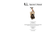
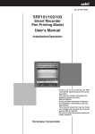
RADIATOR HEAT CURVE PARAMETERS
70
65
Base water SPT
Correction Coef. 0,5
Leaving water temperature setpoint (°C)
60
Correction Coef. 0,8
Correction Coef. 1,0
55
50
45
40
35
30
25
20
-15
-10
Base outd. T.
-5
0
5
10
15
20
Outdoor temperature (°C)
2.3.3. HEAT CURVE AND ROOM TEMPERATURE MANAGEMENT
The heat curve is mainly influenced by the outdoor temperature, but account is also taken of ambient conditions.
2.3.3.1. DECLARED ROOM TERMINAL (DEFAULT)
It is vital for the communicating room terminal to be connected to the PAC HT to take advantage from fine and
precise management of the room temperature and to ensure optimal heating system performance (Refer to the
installation and maintenance manual and to the communicating room terminal for wiring details).
The room terminal continuously sends information about the current temperature and the set room temperature to
PAC HT, which then calculates the optimal water setpoint in the following manner:
²² Room temperature setpoint
²² Variance between the setpoint and the room temperatures
²² PAC HT On/Off control via the room temperature
2.3.3.1.1. ROOM TEMPERATURE SETPOINT
As a default setting, the heat curve is calculated for a desired room temperature of 20°C. As opposed to a dry
contact "limiting" room thermostat, the PAC HT will alter its heat curve if the user changes the set room temperature.
Increasing the room temperature setpoint by one degree (e.g. from 20°C to 21°C) translates into an increase in
the heat curve of between 2° C and 3°C.
11
2.3.3.1.2. VARIANCE BETWEEN TEMPERATURE SETPOINT AND ROOM TEMPERATURE
In theory, the heat curve enables a given room temperature to be maintained, but the
ESC
PAC HT also takes account of the variance between the measured temperature and
the set temperature. Accordingly, the temperature rise is faster when the variance is
Main screens P1 P3
greater, e.g. after night time slow running. Taking account of this ambient temperature
PROG
variance also remedies any errors in heat curve parameter settings.
MAIN MENU
The increase in the heat curve per degree of ambient temperature to be made up can be
ON/OFF-SUMMER/WINTER
configured via the Heat curve offset per room °C parameter. The default setting is 5°C in
HEAT CURVE
the case of radiators (Refer to the § RADIATORS / FLOOR HEATING CONFIGURATION,
DOMESTIC HOT WATER
page 15) for further details).
ROOM TERMINAL
Power on screen
MP
ALARM LOG
OPERATING TIME
BOILER RELIEF
INSTALLATION MENU
ENTER
Password
ENTER
INSTALLATION MENU
WATER PUMP
MI
ENTER
Screen Reference
CE1 CE3
WATER SETPOINT
DOMESTIC HOT WATER
ELECTRIC HEATER
BOILER RELIEF
INSTALLATION CONFIG
MAINTENANCE
COMPRESSOR MNGT
MANUAL DE-ICING
MANUAL OUPUTS
NEW PASSWORD
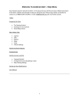
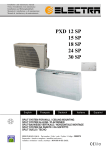
HEAT CURVE OFFSET PER °C OF ROOM TEMPERATURE TO BE MADE UP – RADIATOR CONFIGURATION
15
Addition to heat curve (°C)
10
e.g.:
20° C setpoint and
18° C measured
5
e.g.:
20° C setpoint and
20° C measured
-3
-2
-1
0
1
2
e.g.:
20° C setpoint and
21° C measured
3
-5
-10
-15
Room Temperature variance (Setpoint - Measured, °C)
For example, this means that the room temperature setpoint is at 20°C but the measured temperature is at 19°C,
and that the heat curve will be increased by 5°C. This increase is capped at ± 15°C. This offset will be negative if
the room setpoint is exceeded (Refer to the § PAC HT ON/OFF CONTROL BY ROOM TEMPERATURE, page 13).
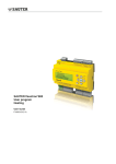
heat curve calculation example
²² Default heat curve (water leaving temperature at 65°C at -7°C, correction coefficient at 0.8)
²² Room temperature setpoint = 21°C
²² Room temperature = 20°C
²² Offset per °C of room temperature = 5°C
12
RADIATOR HEAT CURVE
70
Default heat curve, not corrected by
room temperature setting
Base water SPT
65
Leaving water temperature setpoint (°C)
Heat curve offset by the room
setpoint at 21°C
60
Actual heat curve (offset by the variance
between the 21°C setpoint and
the 20° C measured temperature)
55
50
45
40
35
30
25
20
-15
-10
Base outd. T.
-5
0
5
10
15
20
Outdoor temperature (°C)
2.3.3.1.3. PAC HT ON/OFF CONTROL BY ROOM TEMPERATURE
Power on screen
ESC
Main screens P1 P3
PROG
MAIN MENU
MP
ON/OFF-SUMMER/WINTER
HEAT CURVE
DOMESTIC HOT WATER
When the room terminal is connected, it is possible to adjust the ON/OFF control parameters
of the PAC HT in relation to the room temperature. While the terminal does not act to limit
operation (no ON/OFF operation via a relay) and while the heat curve can be offset negatively
when the room temperature exceeds the desired setpoint, the appliance should still stop
functioning if the room temperature rises too much:
ROOM TERMINAL
ALARM LOG
OPERATING TIME
BOILER RELIEF
INSTALLATION MENU
ENTER
Password
ENTER
INSTALLATION MENU
WATER PUMP
MI
WATER SETPOINT
DOMESTIC HOT WATER
ELECTRIC HEATER
BOILER RELIEF
ENTER
Screen Reference
CI1 CI4
INSTALLATION CONFIG
MAINTENANCE
COMPRESSOR MNGT
MANUAL DE-ICING
MANUAL OUPUTS
NEW PASSWORD
²² Stop diff/SPT (Default: 1°C)
This parameter enables the user to set the maximum difference between the room temperature and
the setpoint to switch the PAC HT off. For example, with a default setting of 1°C, this means that the
appliance will stop operating if the room temperature rises above 21°C for a setpoint (SPT) at 20°C
(even after reducing the heat curve by 5°C, Refer to the § VARIANCE BETWEEN TEMPERATURE
SETPOINT AND ROOM TEMPERATURE, page 12).
13
²² Start diff/SPT (Default: 0.5°C)
This parameter enables the user to set the room temperature offset
compared with the temperature setpoint to restart the PAC HT.
For example, with a default setting of 0.5°C, this means that the
appliance will restart if the room temperature falls below 20.5°C
for a setpoint at 20°C. The room will always tend to be slightly
warmer than the desired set temperature.
This offers the advantage that the regulation system will not
wait for the room temperature to fall again below the setpoint and will anticipate restarting in
order to avoid wide ambient temperature variations. At a setpoint of 20°C, the room should
oscillate between 20°C and 21°C when the house's thermal inertia is taken into account.
The second advantage presents itself when the temperature is reduced for night time slow running.
The PAC HT will anticipate restarting (e.g. will restart at 17.5° C when the temperature is lowered to
17°C) and will enable the heating circuit to be already up to temperature when the system switches
to day time running mode in the morning. In this way, the time taken to raise the temperature will
be reduced, while greatly improving comfort and maintaining the appliance's COP (Coefficient Of
Performance), especially if the timer settings on the room terminal correspond to a peak energy day
tariff from the electricity provider.
There is always a minimum variance of 0.5°C between these two parameters.
2.3.3.2. UNDECLARED ROOM TERMINAL
The room terminal is declared by default and the controller will generate an alarm when the
power to the appliance is switched on when the terminal is not connected.
Power on screen
ESC
Main screens P1 P3
PROG
MAIN MENU
MP
ON/OFF-SUMMER/WINTER
HEAT CURVE
ENTER
DOMESTIC HOT WATER
Screen Reference
TH0 TH4
When the room terminal is not declared, or when communication has been
cut with the PAC HT, the heat curve is calculated as described previously in
relation to the outdoor temperature, as well as in relation to a room setpoint
parameter accessible on the appliance's display via the screen TH0. This screen
displays the information instead of viewing the parameters of the room terminal
(Refer to the § VIEWING ROOM TERMINAL PARAMETERS, page 50). This room setpoint
replaces the room setpoint of the room terminal for the heat curve calculation. Naturally, there
is no longer any control of the room temperature, but if, for example, this room setpoint is
changed from 20°C to 21°C, the heat curve will rise from 2° C to 3° C (Refer to the § ROOM
TEMPERATURE SETPOINT, page 11).
ROOM TERMINAL
ALARM LOG
OPERATING TIME
BOILER RELIEF
INSTALLATION MENU
Power on screen
ESC
Main screens P1 P3
PROG
MAIN MENU
MP
ON/OFF-SUMMER/WINTER
HEAT CURVE
DOMESTIC HOT WATER
ROOM TERMINAL
If you wish not to declare the room terminal, refer to the sub-menu Installation Config. in
the INSTALLATION menu. However, we strongly advise that you connect the room terminal
to the PAC HT.
ALARM LOG
OPERATING TIME
BOILER RELIEF
INSTALLATION MENU
ENTER
Password
ENTER
INSTALLATION MENU
WATER PUMP
MI
WATER SETPOINT
DOMESTIC HOT WATER
ELECTRIC HEATER
BOILER RELIEF
ENTER
Screen Reference
CI1 CI4
INSTALLATION CONFIG
MAINTENANCE
COMPRESSOR MNGT
MANUAL DE-ICING
MANUAL OUPUTS
NEW PASSWORD
14
2.3.4. MANUAL LEAVING WATER TEMPERATURE SETPOINT (CONSTANT HEAT CURVE)
As a default setting, the PAC HT determines the set leaving water temperature in relation to
heay curve parameters and room conditions. However, it is possible to use a leaving water
setpoint that ignores all other conditions. In this event, the room terminal only acts as a system
limiting device. In the same way, the Radiator or Floor Heating configuration has no influence
on operation (the leaving water limitation is deactivated).
Power on screen
ESC
Main screens P1 P3
PROG
MAIN MENU
MP
ON/OFF-SUMMER/WINTER
HEAT CURVE
DOMESTIC HOT WATER
ROOM TERMINAL
ALARM LOG
We STRONGLY ADVISE AGAINST running a heat pump without heat curve control (constant
setpoint) as this will seriously affect installation performance, while reducing occupant comfort.
Accordingly, the constant setpoint control on the PAC HT should only be used in cases of very
special installations, or possibly during system commissioning.
When the manual leaving water temperature setpoint is used, the default setting is 45°C.
OPERATING TIME
BOILER RELIEF
INSTALLATION MENU
ENTER
Password
ENTER
INSTALLATION MENU
WATER PUMP
MI
ENTER
Screen Reference
CE1 CE3
WATER SETPOINT
DOMESTIC HOT WATER
ELECTRIC HEATER
BOILER RELIEF
INSTALLATION CONFIG
MAINTENANCE
COMPRESSOR MNGT
MANUAL DE-ICING
MANUAL OUPUTS
NEW PASSWORD
2.4. RADIATORS / FLOOR HEATING CONFIGURATION
The primary aim of the PAC HT is to produce water up to 65°C in a radiator heating circuit. Nevertheless, it is
possible to make it operate directly and provide leaving water for a floor heating system by adapting the heat
curve. In this case, it is IMPERATIVE to change the PAC HT configuration over to Floor Heating (as opposed
to changing the parameters one by one) to be able to benefit from the advantages of the special features of the
Floor regulation system.
2.4.1. CHANGING FROM RADIATORS TO FLOOR HEATING CONFIGURATION
The PAC HT can be changed to the Floor Heating configuration via a single parameter that
automatically switches all the heat curve parameters from Radiator Heating to Floor heating.
Power on screen
ESC
Main screens P1 P3
PROG
MAIN MENU
MP
ON/OFF-SUMMER/WINTER
HEAT CURVE
DOMESTIC HOT WATER
ROOM TERMINAL
ALARM LOG
At the time of switchover, the programme changes the leaving water setpoint at base outdoor
temperature (Base water SPT, screen L2) from 65°C to 35°C. and the Heat curve offset
per room °C from 5°C to 2°C (screen CE2) changes the law that stops the compressors
relative to the leaving water temperature (Refer to the § COMPRESSOR MANAGEMENT,
page 17). Above all, the switchover activates the leaving water limitation (screen CE3).
Accordingly, in this case, no other parameters need to be changed, other than to adjust the
heat curve or modify the leaving water limitation.
OPERATING TIME
BOILER RELIEF
INSTALLATION MENU
ENTER
Password
ENTER
INSTALLATION MENU
WATER PUMP
MI
WATER SETPOINT
DOMESTIC HOT WATER
ELECTRIC HEATER
BOILER RELIEF
ENTER
Screen Reference
CI1 CI4
INSTALLATION CONFIG
MAINTENANCE
COMPRESSOR MNGT
MANUAL DE-ICING
MANUAL OUPUTS
NEW PASSWORD
15
2.4.2. LEAVING WATER TEMPERATURE LIMITATION
In the Radiators configuration, the heat curve is only limited by the compressors' operating
limits (Refer to the § COMPRESSOR MANAGEMENT, page 17). However, in the Floor Heating
configuration, there exists a self-limiting parameter with a default setting at 45°C. In this way,
the leaving water temperature into the floor heating circuit will never exceed 45°C. This avoids
having to cut out the mechanical limiting thermostat (not supplied, to be fitted by the installer)
that is most frequently set at 50°C.
Power on screen
ESC
Main screens P1 P3
PROG
MAIN MENU
MP
ON/OFF-SUMMER/WINTER
HEAT CURVE
DOMESTIC HOT WATER
ROOM TERMINAL
ALARM LOG
OPERATING TIME
BOILER RELIEF
INSTALLATION MENU
ENTER
Password
ENTER
INSTALLATION MENU
WATER PUMP
MI
ENTER
Screen Reference
CE1 CE3
WATER SETPOINT
DOMESTIC HOT WATER
ELECTRIC HEATER
BOILER RELIEF
INSTALLATION CONFIG
MAINTENANCE
COMPRESSOR MNGT
MANUAL DE-ICING
MANUAL OUPUTS
NEW PASSWORD
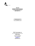
The leaving water temperature limitation acts on the PAC HT's temperature setpoint. If the limit is set at 45°C,
then the maximum leaving water temperature setpoint will be 44°C and this value will be displayed on screen P1
(compressors stop at the set temperature + 1°C, refer to the § COMPRESSOR MANAGEMENT, page 17).
FLOOR HEATING HEAT CURVE
36
Base water SPT
34
Leaving water temperature setpoint (°C)
Correction Coef. 0,5
Correction Coef. 0,8
32
Correction Coef. 1,0
30
28
26
24
22
20
-15
-10
Base outd. T.
-5
0
5
Outdoor temperature (°C)
16
10
15
20
2.5. COMPRESSOR MANAGEMENT
2.5.1. TECHNICAL OPERATING LIMITS
2.5.1.1. IN RELATION TO OUTDOOR TEMPERATURE
The outdoor temperature plays an important role in limiting the operation of the two stage system. The PAC HT
limits itself automatically and cannot operate in two stages at outdoor temperature > 7°C. In this case, the leaving
water temperature is limited at 55°C in single compressor operation in heating mode and at 60°C in Domestic
Hot Water mode (Refer to the § DHW).
The compressors are always subject to the following anti-short cycle timers (other than in an alarm situation):
²² Minimum ON: 120 seconds
²² Minimum OFF: 60 seconds
²² Between two starts: 300 seconds
2.5.1.2. IN RELATION TO ENTERING WATER TEMPERATURE
The entering water temperature also plays a role to authorise, or otherwise, operation in two stage mode. For entering
water temperature < 23°C, two stage operation is never authorised (e.g. case of commissioning). Accordingly,
the PAC HT will operate in single stage mode without a minimum limitation on the entering water temperature.
Nevertheless, we strongly advise against starting a PAC HT on a heating circuit with a
water temperature below 10°C.
SINGLE /TWO STAGE OPERATING LIMITATIONS
70
65
Leaving water temperature setpoint (°C)
60
55
50
TWO
STAGE
45
SINGLE
STAGE
40
35
30
Two stage – min. entering water T.
25
Two stage – max. leaving water T.
20
Single stage – max. leaving water T.
15
10
-25
-20
-15
-10
-5
0
Outdoor temperature (°C)
17
5
10
15
20
25
2.5.2. CHOICE OF COMPRESSOR IN RELATION TO THE HOUSE'S THERMAL LOAD
(HEATING MODE)
2.5.2.1. C2 SMALL COMPRESSOR DEFAULT BALANCE POINT
The heat curve parameters enable the regulation system to determine the outdoor
temperature above which the capacity from the small compressor will be sufficient
to heat the house to the desired temperature setpoint. This balance point (viewable
on screen L3) is around +6°C with the default heat curve (depending on the model
of PAC HT).
Power on screen
ESC
Main screens P1 P3
PROG
MAIN MENU
MP
ON/OFF-SUMMER/WINTER
ENTER
Screen Reference
HEAT CURVE
L1 L4
DOMESTIC HOT WATER
ROOM TERMINAL
ALARM LOG
OPERATING TIME
BOILER RELIEF
INSTALLATION MENU
Outdoor temperature > Balance point
Small compressor
Outdoor temperature < Balance point
Full capacity
Full capacity means both compressor stages or large C1 compressor in operation. If the operating limits of the
two-stage compressor prevent it from starting, then the large compressor will be selected.
In this way, the PAC HT engages the compressor(s) best suited to achieve the most appropriate Comfort/Electricity
consumption compromise. When conditions allow, the PAC HT benefits from the small compressor operating
on its own, which is half as powerful, to provide sufficient capacity for heating needs, while guaranteeing high
performance and smoother operation. This also leads to longer service life.
2.5.2.2. AUTOMATIC BALANCE POINT / LACK OF CAPACITY
Power on screen
ESC
Main screens P1 P3
PROG
MAIN MENU
MP
ON/OFF-SUMMER/WINTER
HEAT CURVE
ENTER
Screen Reference
L1 L4
DOMESTIC HOT WATER
In the case where the heat curve is not entirely accurate, and therefore where
the theoretical default balance point is also incorrect, the PAC HT is designed
to detect that the small compressor is inadequate to heat the house due to a
lack of capacity. After a few minutes operation, if the water temperature is not
rising fast enough, the controller will start the compressor(s) at full capacity,
while automatically updating the balance temperature with the current outdoor
temperature. Accordingly, at the next start-up, the PAC HT will select full capacity
running instead of attempting to start the small compressor again.
ROOM TERMINAL
ALARM LOG
OPERATING TIME
BOILER RELIEF
INSTALLATION MENU
The automatic balance temperature is limited by the default balance temperature ± 2°C.
It is possible to reset this automatic balance temperature. It will then revert to the default value calculated by the
controller (screen L3).
It is also possible that the controller detects a lack of capacity in the case where the volume of water
in the installation is greater than the recommended volume (200 to 250 L). If a very high volume is
present, the heating circuit's inertia will be stronger and the rate of the rise in water temperature will
be slower. In this event, the PAC HT will change to full capacity operation more easily with the aim
of raising the water temperature faster for greater comfort.
18
2.5.2.3. ONE COMPRESSOR NOT STARTING
In the case where the PAC HT detects that one of the compressors has not started, it will prevent any future startup of the compressor in question and automatically switch over to the other. This feature ensures that a minimum
of heating is provided in the residence in compressor alarm operating mode.
2.5.3. MANUAL COMPRESSOR MANAGEMENT
As part of PAC HT testing and maintenance, it is possible to manually force the choice of one
or both compressors. When the appliance has to start, it will either automatically choose the
best compressor staging or the staging chosen manually.
Power on screen
ESC
Main screens P1 P3
PROG
MAIN MENU
MP
Three manual management choices are possible:
ON/OFF-SUMMER/WINTER
²² 1 stage – Comp. 2
Choice of C2 small compressor
²² 1 stage – Comp. 1
Choice of C1 large compressor
²² 2 stages
Choice of both compressors in two stages
HEAT CURVE
DOMESTIC HOT WATER
ROOM TERMINAL
ALARM LOG
OPERATING TIME
BOILER RELIEF
INSTALLATION MENU
ENTER
Password
ENTER
INSTALLATION MENU
WATER PUMP
MI
WATER SETPOINT
DOMESTIC HOT WATER
ELECTRIC HEATER
BOILER RELIEF
INSTALLATION CONFIG
MAINTENANCE
ENTER
Screen Reference
CP1
COMPRESSOR MNGT
MANUAL DE-ICING
MANUAL OUPUTS
NEW PASSWORD
The 2 stages choice ensures that the appliance's operating limits are not exceeded. If the
outdoor and entering water temperature conditions do not permit the two compressors
to start, the PAC HT will remain inactive and the "Waiting Water T" message will be
displayed.
Manual management of the compressors cannot exceed a period of 30 minutes. At the end of this
period, the compressors management mode will revert to automatic. This avoids the compressor
setting being forgotten when the site is left, for example.
19
2.5.3.1. COMPRESSOR CONTROL IN RELATION TO WATER temperature IN HEATING
MODE
2.5.3.1.1. COMPRESSOR START-UP
Even though the water temperature setpoint (calculated by the heat curve) is that of the leaving water (65°C
maximum), the entering water temperature (equal to the leaving water temperature as the compressors are stopped)
is used for start-up in accordance with the following conditions:
Entering water < Leaving setpoint – DT compressor(s) – 2°C
T compressor(s) is the T variance (Leaving – Entering) registered when the compressors previously stopped. The
default values in Heating mode (in the case of the power supply being switched on) are 5°C with the C2 small
compressor and 10°C for the two stage compressor, and 3.5°C and 7°C for an Floor heating application (if the type
of heating application has been configured, Refer to the § RADIATORS / FLOOR HEATING CONFIGURATION,
page 15).
The control system always considers that the two stage T is equal to 2 x T C2 as the two stage compressor is
theoretically twice as powerful as the small compressor.
In this way, the PAC HT always operates for the right amount of time (if the minimum water volume in the installation
is correct) and adapts to the change in compressor staging and the different not nominal water flows.
This does not mean that the PAC HT accepts a variable water flow, but that it adapts to
different heating installations in which the flow is not necessarily the recommended flow.
Example
For a leaving temperature setpoint at 50°C in a Radiator application:
C2 will be authorised if Entering water T. < 43°C (50°C – 5°C – 2°C).
C1+C2 will be authorised if Entering water T. < 38°C (50°C – 10°C – 2°C).
2.5.3.1.2. COMPRESSOR STOP
Compressor stop is managed by the temperature of the leaving water in accordance with the following:
Leaving water T. > Leaving water setpoint + Stop offset T.
The stop offset T. is set at 3°C in the Radiator application and at 1°C in the Floor heating application.
Example
For a leaving water setpoint of 50°C in a Radiator application:
The compressors will stop at a leaving water temperature > 53°C (50°C + 3°C).
This stop condition is not followed in the case where the leaving water setpoint is already limited by overall
compressor operation parameters (55°C in single stage operation and 65°C in two stage operation for example).
The PAC HT control system will not allow the leaving water temperature to exceed its operating limits, irrespective
of the requested setpoint.
Example
For a leaving water setpoint at 64°C in a Radiator application at -5°C outdoor temperature:
The compressors will stop at a leaving water temperature > 65°C (and not 67°C).
20
2.6. DOMESTIC HOT WATER
This function requires the installation of a DHW tank or a heat exchange system to supply the DHW
tank (plate exchanger type) compatible with the capacity and the water temperatures of a PAC HT.
The DHW tank available as a kit guarantees effective operation of the DHW option as it includes an
internal heat exchanger with a sufficient surface area (over 3m²) and a back-up heating resistance. In
the case of the use of a different system, some functions (e.g. Legionnaires' Disease Protection) will be inoperative
and there is no guarantee that the satisfactory DHW temperature will be reached.
It is also necessary to connect a specific DHW temperature sensor to the appliance's regulation system (Refer to
the Installation Manual).
Two separate menus on the display are used for setting DHW parameters. In the main menu, the DHW screens
provide simple everyday user access (temperature setpoint, timer programming …) while the Installation menu
covers the configuration choices possible at the time of PAC HT installation (DHW activation, setting off-peak
hours operation, Legionnaires' Disease Protection, room temperature management, water pump management …).
2.6.1. DHW FUNCTION ACTIVATION
It is important to connect the DHW sensor to the controller before proceeding with the activation
of the DHW. If this is not done, a DHW sensor alarm AL04 will appear 10 seconds after the
activation.
Power on screen
ESC
Main screens P1 P3
The function is activated via the screen IE1 in the Installation menu.
PROG
MAIN MENU
MP
ON/OFF-SUMMER/WINTER
HEAT CURVE
DOMESTIC HOT WATER
ROOM TERMINAL
ALARM LOG
OPERATING TIME
BOILER RELIEF
INSTALLATION MENU
ENTER
Password
ENTER
INSTALLATION MENU
WATER PUMP
WATER SETPOINT
MI
ENTER
Screen Reference
IE0 IE8
DOMESTIC HOT WATER
ELECTRIC HEATER
BOILER RELIEF
INSTALLATION CONFIG
MAINTENANCE
COMPRESSOR MNGT
MANUAL DE-ICING
MANUAL OUPUTS
NEW PASSWORD
2.6.2. DHW DEMAND AND ROOM TEMPERATURE MANAGEMENT
2.6.2.1. DHW DEMAND
The PAC HT considers that there is a demand for DHW production when the temperature read by the DHW
sensor falls 2° C below the setpoint. For example, if the setpoint is 50°C, there will be a demand for DHW for a
temperature measured below 48°C.
The demand for DHW is considered as satisfied when the DHW temperature exceeds the setpoint by 2°C (Diff.
comp. stop, screen IE8). For a setpoint at 50°C, this means that the DHW temperature is going to oscillate between
48°C and 52°C.
21
2.6.2.2. DHW MANAGEMENT RELATIVE TO ROOM TEMPERATURE
When the room terminal is connected, the PAC HT can decide whether to give priority to Heating or DHW production.
The DHW or Heating priority can be configured via two parameters:
²² Min. Dif./Room T. for DHW start (Default setting: 2°C)
If the room temperature is lower than the room setpoint minus
this value, the PAC HT remains in Heating mode until the room
temperature is restored above this limit. For example, for a room
setpoint of 20°C, the switchover to DHW will only occur if the
room temperature is above 18°C (during 5 consecutive minutes).
²² Max. delay (Default setting: 60 minutes)
Beyond this period of demand for DHW production, the PAC HT will automatically switch to DHW
mode, irrespective of the room temperature. This time period, set at 60 minutes is a good compromise
between heating comfort and readily available domestic hot water. Moreover, if the timer has been
programmed or if an off-peak hours electricity relay has been connected to the PAC HT, this set-up
ensures that the optimum time period for DHW production is not missed.
To afford greater priority to Heating for example, the Max delay can just be increased (up to 3 hours) and/or the
Min. Dif./Room T. for DHW start can be changed to 0°C instead of 2°C. In this case, the PAC HT will be able
to remain in Heating mode for 3 hours or until the room temperature has reached the room setpoint. However,
there is a risk of not having DHW at the desired temperature at the end of the off-peak period, for example.
On the other hand, priority can be afforded to DHW by changing the Max. delay to 0 minute.
2.6.2.3. PAC HT IN SUMMER MODE
When the PAC HT is in Summer mode (Refer to the § SUMMER/WINTER, page 7), the room temperature is no
longer taken into account and the changeover to DHW mode is instantaneous during a demand for DHW production.
2.6.2.4. ROOM TERMINAL NOT CONNECTED
When the room terminal is not connected to the PAC HT, the changeover to DHW mode is identical to operation
in Summer mode.
2.6.3. COMFORT/ECO TEMPERATURE SETPOINTS (SCHEDULING)
The user can set the DHW parameters to fulfil all types of needs. To achieve this, the PAC HT proposes two
temperature setpoints: Comfort and Eco, as well as two operating modes: pERMANENT Comfort and Comfort/
Economy. Similarly, there are TWO types of timer programming: via digital input (dry contact) or via daily scheduling
(timer programming).
2.6.3.1. ECO/COMFORT TEMPERATURE SETPOINTS
The first screen on the DHW menu is only devoted to viewing system
operation (current temperature setpoint and current mode, Comfort
or Eco) and does not enable any modifications.
Power on screen
ESC
Main screens P1 P3
PROG
MAIN MENU
MP
ON/OFF-SUMMER/WINTER
HEAT CURVE
DOMESTIC HOT WATER
ENTER
Screen Reference
ES0 ES10
ROOM TERMINAL
ALARM LOG
OPERATING TIME
BOILER RELIEF
INSTALLATION MENU
22
²² Comf./Eco. mode (Default setting)
The mode determines how the appliance is going to choose the DHW temperature setpoint.
As the default setting in Comf./Eco., this means that the PAC HT is going to switch between the two Comfort and
Economy temperature setpoints either in relation to the off-peak hours status (connection to the electricity meter)
or in relation to the daily scheduling.
It is possible to configure the mode in Perm. Comf. (for permanet Comfort). This will continuously force the
DHW setpoint to the Comfort setpoint (not recommended).
²² Comfort and Eco setpoint (Default settings: 50°C and 45°C)
These are the temperature setpoints used in relation to the current mode. These setpoints provide domestic hot
water at the right temperature in Comfort mode (e.g. hot water production during off-peak hours at night) and
restart production at a lower temperature when the tank has cooled down (e.g. during the day). In this way, comfort
is maintained for the user, while ensuring that the PAC HT operates under optimum conditions.
To prevent any restart of DHW production during the day time and to produce DHW only during the
night, the user just has to set the Eco temperature at 10°C (minimum setting). This setting corresponds
to the Anti-freeze protection setting.
These setpoints have been chosen to be compatible with compressor operation. If they are increased
to values beyond 55°C, the PAC HT will be unlikely to supply DHW at the desired temperature.
This will lead to the possible start-up of the electric heat (fitted in the DHW tank as an option) and
would considerably increase the system’s electricity consumption. In the worst case, and insofar as
the system’s priority is to always provide DHW at the required temperature, it is possible that DHW could only
be produced by the electric heater. These default settings guarantee that DHW will be produced
without recourse to the electric heater.
WE STRONGLY ADVISE AGAINST INCREASING THE
DHW TEMPERATURE SETPOINTS BEYOND 53°C.
23
2.6.3.2. COMFORT/ECO CHANGEOVER
To benefit from the dual temperature setpoint function, the DHW mode must be configured
ESC
in Comf./Eco.. The temperature setpoint point changeover can then be programmed in two
different ways.
Power on screen
Main screens P1 P3
PROG
MAIN MENU
²² Off-peak hours input
²² Daily scheduling
MP
ON/OFF-SUMMER/WINTER
HEAT CURVE
DOMESTIC HOT WATER
ROOM TERMINAL
ALARM LOG
OPERATING TIME
BOILER RELIEF
INSTALLATION MENU
ENTER
Password
ENTER
INSTALLATION MENU
WATER PUMP
MI
WATER SETPOINT
ENTER
Screen Reference
IE0 IE8
DOMESTIC HOT WATER
ELECTRIC HEATER
BOILER RELIEF
INSTALLATION CONFIG
MAINTENANCE
COMPRESSOR MNGT
MANUAL DE-ICING
MANUAL OUPUTS
NEW PASSWORD
2.6.3.2.1. OFF-PEAK HOURS INPUT
The default parameters are set on the PAC HT to use the off-peak hours contact
(ID11 digital input on the conttroller). It is also possible to configure the type of
switching of this input to Normally Open (NO, by default) or Normally Closed
(NC). The NO parameter setting means that the DHW will use the Comfort
setpoint (e.g. at night) when the contact is closed. Therefore, as a default, if the
off-peak hours contact is not connected, the DHW will remain permanently in
Eco mode (as the unwired contact is open).
2.6.3.2.2. DAILY SCHEDULING
THIS FUNCTION REQUIRES THE ROOM TERMINAL TO BE INSTALLED.
To gain access to the timer programming screens from the Main Menu, it is previously necessary to switch the OffPeak hours – ID11 parameter to Scheduling
The time is programmed via the 7 screens (ES4 to ES10) available for this purpose
(1 per day of the week). Two time periods can be programmed for each day.
Power on screen
ESC
Main screens P1 P3
PROG
MAIN MENU
MP
ON/OFF-SUMMER/WINTER
HEAT CURVE
DOMESTIC HOT WATER
ENTER
The time periods, marked 1. and 2., represent the hours when the Comfort mode
is activated (higher setpoint, START to start operation and STOP to stop operation).
Outside these hours, the DHW will operate at the Eco setpoint (i.e. the lower
setpoint).
Screen Reference
ES0 ES10
ROOM TERMINAL
ALARM LOG
OPERATING TIME
BOILER RELIEF
INSTALLATION MENU
24
As a default setting, the Comfort mode is activated every day between Midnight and 05h00 in the morning and
between 23h00 and Midnight. In this way, the PAC HT mainly produces DHW during the night when the demand
for heating is generally reduced, while benefiting from any possible off-peak electricity tariff.
The time periods can be altered in increments of one hour, while the minutes can be altered in increments of 10
minutes.
The display automatically requires a difference of at least one hour to be maintained between the START and STOP
times to avoid inverting these two time settings (START time < STOP time - 1). If the two time periods overlap, the
controller will take account of the earliest start time and the latest stop time.
It is also possible to use only one time period per day by deactivating time period 2 ("--" parameter to be set on
START time). If the first time period is deactivated, the DHW will remain in Eco mode.
Time period 2 deactivation (e.g. case of DHW production only in the morning).
The START hour of this time period has to be changed to "--" (via the Up or
Down arrows).
Both time periods deactivated. In this case, the Eco mode runs continuously
during the day (e.g. useful in a second home where the DHW mode can be
deactivated during the week. The START hour of the time period has to be
changed to "--", that willl automatically deactivate time period 2.
2.6.3.2.3. EXAMPLES OF DIFFERENT DHW OPERATING PATTERNS
These examples are provided for information purposes only. The different heating or DHW
production timeframes are not necessarily representative of all possible installations.
These heating times are closely linked to the PAC HT’s operating conditions, to the type
of heating emitters and the level and frequency of demand for DHW.
Heating and DHW mode operation in relation to scheduling,
restart after night time running
DHW TEMPERATURE (°C)
55
DHW > Eco setpoint + 2°C
End of DHW
50
45
40
35
DHW demand but roomT.
< 18°C for a setpoint at
20°C
DHW SPT
DHW T.
30
22
ROOM TEMPERATURE (°C)
21
20
19
Room SPT
18
Room T.
17
Room T. > 18°C for a
setpoint at 20°C
DHW production
16
HEATING / DHW MODE
15
1
HEATING
MODE
DHW
MODE
HEATING
MODE
Heating
mode
DHW
MODE
DHW Mode
0
04:30
05:00
05:30
06:00
06:30
07:00
07:30
08:00
08:30
TIME OF DAY
25
09:00
09:30
10:00
10:30
11:00
11:30
12:00
3 DHW schedulings (via off-peak hours input or daily scheduling)
without consideration for Heating demand
Off-peak input connected or default daily scheduling (Comfort between 23h00 and 05h00 in the morning, Eco
the rest of the time), Comfort and Eco setpoints at 50°C and 45°C default settings
60
58
56
DHW TEMPERATURE (°C)
DHW SPT
DHW OFF at Comfort SPT + 2°C
Temp. exceeded due to system inertia.
54
DHW T.
52
50
48
46
44
DHW > Eco SPT - 2°C
No restart in Eco mode
42
DHW < Eco SPT - 2°C
Restart in Eco mode
40
22
23
00
01
02
03
04
05
06
07
08
09
10
11
12
13
TIME OF DAY
14
15
16
17
18
19
20
21
22
23
00
01
Off-peak input connected or daily scheduling with a restart at midday (Comfort between 0h00 and 05h00 in the
morning and between 12h30 and 14h00, Eco the rest of the time), Comfort and Eco setpoints at 50°C and 45°C
default settings
60
58
DHW TEMPERATURE (°C)
56
DHW SPT
DHW OFF at Comfort SPT + 2°C
Temp. exceeded due to system inertia.
54
DHW T.
52
50
48
46
44
42
40
DHW < Eco SPT - 2°C
Restart in Eco mode
DHW > Eco SPT - 2°C
No restart in Eco mode
22
23
00
01
02
03
04
05
06
07
08
09
10
11
12
TIME OF DAY
26
13
14
15
16
17
18
19
20
21
22
23
00
01
Off-peak input connected or default daily scheduling (Comfort between 23h00 and 05h00 in the morning, Eco
the rest of the time), set Comfort and Eco temperatures at 50°C and 10°C, no DHW production during the day.
60
DHW OFF at Comfort SPT + 2°C
Temp. exceeded due to system inertia.
DHW SPT
DHW T.
DHW TEMPERATURE (°C)
50
40
30
No restart during the day,
Eco setpoint at 10°C.
20
10
0
22
23
00
01
02
03
04
05
06
07
08
09
10
11
12
13
TIME OF DAY
14
15
16
17
18
19
20
21
22
23
00
Default scheduling settings during the week but continuous operation in Comfort mode during the weekend.
The timer just has to be programmed specifically for Saturday and Sunday in the following way:
27
01
2.6.4. "QUICK HEAT-UP" FUNCTION
This function can be used when DHW is needed in a hurry and the tank is not
hot enough as, for example when you return from holidays with the PAC HT in
MAIN OFF mode or even switched off from the power supply (not recommended).
Power on screen
ESC
Main screens P1 P3
PROG
MAIN MENU
MP
ON/OFF-SUMMER/WINTER
ENTER
HEAT CURVE
Screen Reference
ES0 ES10
DOMESTIC HOT WATER
ROOM TERMINAL
ALARM LOG
OPERATING TIME
BOILER RELIEF
INSTALLATION MENU
When the "QUICK HEAT-UP" function is activated, the aim is to heat the DHW as rapidly as possible. The PAC HT’s
controller acts in the following manner :
²² The system is switched to forced DHW mode, and ignores the room temperature conditions,
²² The DHW setpoint changes to the Comfort setpoint, even is the current mode was Eco,
²² The electric heater is authorised to start at the same time as the compressors to provide extra heating
capacity (Refer to the § ADDITIONAL ELECTRIC HEATER MANAGEMENT, page 29).
When the DHW reaches the setpoint + 2°C (Refer to the § DHW DEMAND, page 21), the "QUICK HEAT-UP"
function will be automatically deactivated and the PAC HT will return to its original operating mode.
2.6.5. COMPRESSOR MANAGEMENT
The operating limits of the two compressors in two stage operation are the same as in Heating mode as these
are their technical limits. However, the choice between the small C2 compressor or two stage C1+C2 operation
is always made to provide the best compromise between DHW temperature / capacity supplied / performance.
SINGLE /TWO STAGE OPERATING LIMITATIONS
70
Leaving water temperature setpoint (°C)
65
60
55
TWO
STAGE
50
45
SINGLE
STAGE
40
35
30
Two stage – min. entering water T.
25
Two stage – max. leaving water T.
20
Single stage – max. leaving water T.
15
10
-25
-20
-15
-10
-5
0
Outdoor temperature (°C)
28
5
10
15
20
25
2.6.5.1. OUTDOOR TEMPERATURE ABOVE +2°C AND UP TO +42°C
The C2 compressor operates on its own but the maximum leaving water temperature is increased to 60°C instead
of 55°C in Heating mode. In this way, the PAC HT does not supply surplus capacity and does ensure that the
hottest water possible is available under the most efficient operating condictions.
Note that DHW production is allowed up to +42°C outdoor temperature, with water produced at 60°C. Beyond
42°C outdoor temperature, the PAC HT will automatically shut down to avoid damaging the compressor (the
same is true in Heating mode).
2.6.5.2. BELOW 2°C OUTDOOR TEMPERATURE
The compressors operate in two stage mode with a leaving water temperature at 65°C. The PAC HT then provides
its maximum capacity and maximum water temperature, while maintaining good performance. The small compressor
will start operating if the entering water temperature is too low (below 23°C e.g. at a PAC HT start-up).
2.6.5.3. COMPRESSOR NOT STARTING
In this case, as in Heating mode, if it is possible the PAC HT will produce DHW with the compressor which is
authorised to start.
2.6.6. ADDITIONAL ELECTRIC HEATER MANAGEMENT
The PAC HT controller is capable of managing additional electric heater fitted inside the DHW tank (Refer to the
example of § LEGIONNAIRES' DISEASE PROTECTION FUNCTION, page 30). This additional heater can be
used in 4 circumstances.
2.6.6.1. SET TEMPERATURE UNATTAINABLE WITH THE COMPRESSORS
When the PAC HT is already in DHW production mode with the compressor(s) in operation and the maximum
leaving water temperature has been reached (60°C with C2 compressor or 65°C with C1+C2), the controller
considers that it is no longer possible to heat the DHW via the compressors. At this point, if the DHW temperature
is below the DHW setpoint minus 2°C (e.g. 55°C for a setpoint of 57°C), then the electric heater is authorised
to operate until the DHW temperature reaches the setpoint. In the same time, the PAC HT will change back into
Heating mode.
When the PAC HT is in Heating mode and a demand for DHW production appears, the controller estimates
whether it is possible to produce DHW with the compressors. If the DHW temperature is too high, the appliance
will remain in Heating mode but the electric heater will be able to operate in accordance with the previous rules.
It is for this reason, as recommended above, that it is very important not to set the DHW setpoints
too high in order to avoid starting the electric heater too frequently.
2.6.6.2. LEGIONNAIRES' DISEASE PROTECTION FUNCTION
Refer to the corresponding paragraph.
2.6.6.3. "QUICK HEAT-UP" FUNCTION
Refer to the corresponding paragraph.
2.6.6.4. APPLIANCE FAULT PREVENTING START-UP OF THE TWO COMPRESSORS
If neither of the two compressors can provide DHW production, then the electric heatER will automatically take
over the role with the same setpoint.
29
2.6.7. LEGIONNAIRES' DISEASE PROTECTION FUNCTION
This function requires the room terminal to be connected to the PAC HT. If the terminal
has not been connected or has been disconnected for some reason, the Legionnaires'
Disease protection function is deactivated.
This function is activated as a default setting. Every Saturday at 01h00 in the morning, the
DHW temperature will be raised to 65°C and this temperature will be maintained during
1 hour.
It is possible to change the day of the week, the time of the setpoint change, the setpoint
itself, although it is recommended to maintain it at 65° C, and the length of time the
temperature is maintained at this level. This time period means that if DHW is drawn off
during one hour after the setpoint is teached, causing the DHW temperature to drop below
the setpoint minus 2°C, then DHW production will restart until the setpoint is maintained
continuously for one hour. In the unlikely event of this sequence re-occuring several times,
the Legionnaires' Disease Protection function will automatically deactivate after 5 hours.
Under normal operating conditions, the function is deactivated at the end of the 1 hour
period of maintaining the temperature at 65° C.
Power on screen
ESC
Main screens P1 P3
PROG
MAIN MENU
MP
ON/OFF-SUMMER/WINTER
HEAT CURVE
DOMESTIC HOT WATER
ROOM TERMINAL
ALARM LOG
OPERATING TIME
BOILER RELIEF
INSTALLATION MENU
ENTER
Password
INSTALLATION MENU
WATER PUMP
ENTER
WATER SETPOINT
MI
ENTER
Screen Reference
IE0 IE8
DOMESTIC HOT WATER
ELECTRIC HEATER
BOILER RELIEF
INSTALLATION CONFIG
MAINTENANCE
COMPRESSOR MNGT
MANUAL DE-ICING
MANUAL OUPUTS
NEW PASSWORD
If it is intended to use this function, an electric heater must be fitted as it is the only way to attain the required
DHW temperature.
70
EXAMPLE OF DHW PRODUCTION AND OPERATION OF THE LEGIONNAIRES' DISEASE
PROTECTION WITH THE USE OF THE ELECTRIC HEATER
DHW TEMPERATURE (°C)
65
Re-start with electric
heater alone
60
Changeover to Legionnaires'
Disease Protection
DHW drawn off during one
hour for the temperature
being maintained at 65°C.
55
Compressors stop at the
leaving water temp. limit
electric heater
DHW SPT
DHW T.
50
45
Changeover to Comfort mode
Compressors start-up
40
17
18
19
20
21
22
23
00
TIME OF DAY
30
01
02
03
04
05
06
2.6.8. HEATING D DHW CHANGEOVER
When the PAC HT changes from Heating mode to DHW mode, the following sequence of events occurs:
1. Compressors stop.
2. Post-pump waiting time (Post-pump time, Default setting: 60s) with the water
pump running.
3. Water pump stops.
4. DHW valve changeover (Valve time, Default setting: 90s).
5. Water pump runs during the pre-pump waiting time (Pre-pump time, Default
setting: 60s).
6. One or both compressors start.
Power on screen
ESC
Main screens P1 P3
PROG
MAIN MENU
MP
ON/OFF-SUMMER/WINTER
HEAT CURVE
DOMESTIC HOT WATER
ROOM TERMINAL
ALARM LOG
The changeover from DHW mode into Heating mode occurs in the same manner.
OPERATING TIME
BOILER RELIEF
INSTALLATION MENU
ENTER
Password
ENTER
INSTALLATION MENU
WATER PUMP
WATER SETPOINT
MI
ENTER
Screen Reference
IE0 IE8
DOMESTIC HOT WATER
ELECTRIC HEATER
BOILER RELIEF
INSTALLATION CONFIG
MAINTENANCE
COMPRESSOR MNGT
MANUAL DE-ICING
MANUAL OUPUTS
NEW PASSWORD
When the valve position changes, the water pump is stopped to avoid mixing the two Heating and DHW circuits,
even though it is a joint circuit. In this way, especially in summer when the Heating is stopped, cold water is
prevented from being dispatched to the DHW tank (Heating
DHW) or from the hot water tank to the cold
Heating circuit (DHW
Heating). The aim is to maximise the system's overall performance and user comfort.
The time for valve changeover, stop or not of the water pump, and the post and pre-pump time settings, can be
changed via the screens IE6 and IE7.
When the PAC HT is actually changing from Heating mode to DHW mode, it displays "No room
need" on the main screen P1. In the event of doubt about actual appliance operating status, the
is displayed on the right of screen P2. If the PAC HT is producing DHW with the
moving icon
electric heater, this icon will not appear as it is associated with the changeover of the DHW valve
(refer to the green warning light on the DHW tank supplied as an option).
In the case where the DHW tank used is not the model available as an option, it is possible that the
PAC HT changes to DHW mode but is unable to start the compressor(s) due to excessively high
appliance entering water temperature. In this case, the PAC HT will remain in DHW mode for 15
minutes (in case the entering water cools down enough for the compressor(s) to start) and will then
change to Heating mode for at least 30 minutes while activating the electric heater. This avoids the
appliance constantly changing from one mode to the other in case of continuous a demand for DHW
(possible if the DHW temperature sensor is placed incorrectly.
31
2.7. INLINE ELECTRIC HEATER
The inline electric heater is an option of the PAC HT that is not equipped with an integrated heater.
The PAC HT's controller can manage 2 electric heating stages in 2 different modes: "Emergency only" and "Backup + Emergency".
It is not possible to connect or activate simultaneously the Electrical Heater and the Boiler Relief
functions as they use the same digital outputs.
2.7.1. ELECTRIC HEATER FUNCTION ACTIVATION
The Electric Heater function is activated via screen EH1 in the Installation menu.
Power on screen
ESC
Main screens P1 P3
PROG
MAIN MENU
MP
ON/OFF-SUMMER/WINTER
HEAT CURVE
DOMESTIC HOT WATER
ROOM TERMINAL
ALARM LOG
OPERATING TIME
BOILER RELIEF
INSTALLATION MENU
ENTER
Password
ENTER
INSTALLATION MENU
WATER PUMP
MI
WATER SETPOINT
DOMESTIC HOT WATER
ENTER
Screen Reference
EH0 EH7
ELECTRIC HEATER
BOILER RELIEF
INSTALLATION CONFIG
MAINTENANCE
COMPRESSOR MNGT
MANUAL DE-ICING
MANUAL OUPUTS
NEW PASSWORD
2.7.2. EMERGENCY AND BACK-UP + EMERGENCY COMMON FUNCTIONS
These two operating modes have relatively different management systems (see the § dedicated to each mode) but
some functions are common to both modes. They are identified under "BACK-UP/EMERG." in the Electric heater
menu screens.
2.7.2.1. MANAGEMENT BY ROOM TEMPERATURE
The aim of this function is, as a default setting, not to use the electric heaters as the compressors are used, as they
are intended to guarantee maximum comfort and energy savings.
Electric Heater management via the room temperature is linked to compressor
management (Refer to the § PAC HT ON/OFF CONTROL BY ROOM
TEMPERATURE, page 13).
The Additional diff./compressors parameter offsets the ON/OFF room
setpoint of the electric heaters from that of the compressors.
Increasing this parameter (e.g. to -2.0°C) will reduce user comfort slightly but will also reduce electricity consumption.
Changing it to 0°C will guarantee maximum comfort but can significantly increase electricity consumption.
32
Example
For a room temperature setpoint at 20°C with the parameters Stop diff./SPT and Start diff./SPT at their original
settings (respectively 1.0°C and 0.5°C) and Additional diff./compressors at -1.0°C:
²² The electric heaters will be authorised to start if
²² The compressors will be authorised to start if room
²² The electric heaters will stop if room temperature
²² The compressors will stop if room temperature
room temperature < 19.5°C.
temperature < 20.5°C.
> 20°C.
> 21°C.
Electric Heaters
ON/OFF
19.5°C
Compressors
ON/OFF
20°C
20.5°C
Room
temperature
21°C
Room temperature setpoint
Additional diff. /
compressors
at -1.0°C
Just as for boiler relief, the room temperature management is entirely deactivated when
the room terminal is not connected. Accordingly, we strongly advise you to install it.
2.7.2.2. MANAGEMENT BY WATER TEMPERATURE
The overall logic is that the electric heaters should operate for the shortest
possible time while enabling the required water temperature to be reached
(comfort optimisation), without it being exceeded (unnecessary electricity
consumption).More over, the stop sequence of the electric heaters in relation
to water temperature is offset, favouring the single-stage operation (i.e. the
less powerful of the two stages) in addition to the compressors and avoiding unnecessary electricity consumption.
3 parameters define operation of the 2 electric stages in relation to the leaving water temperature setpoint:
²² Start Diff.
Both heater stages are authorised to start if:
Leaving water T. < Leaving water setpoint + Start diff.
For a setpoint at 50°C, the heater
stages are authorised to start if
Leaving water T. < 47°C.
ON/OFF Stage 1
²² Stop diff. S2
The second heater stage (normally
the most powerful stage in the case of
an unequal two-stage set-up: 2kW +
4kW) will stop if:
ON/OFF Stage 2
47°C
49°C
50°C
Set outlet
water T.
Leaving water T. > Leaving water setpoint + Stop diff. S2
For a setpoint at 50°C, the 2nd heater stage will stop if Leaving water T. > 49°C.
²² Stop diff. S1
The first stage of the heater will stop if:
Leaving water T. > Leaving water setpoint + Stop diff. S1
For a setpoint at 50°C, the 1st heater stage will stop if Leaving water T. > 50° C.
33
Leaving
water
Temperature
2.7.2.3. LEAVING WATER TEMPERATURE LIMITATION
The controller can manage (function activated as a default setting) the electric
heater's leaving water temperature (in a theoretical manner, given there is no
electric heaters leaving water sensor).
The controller considers that the heaters supply a capacity equivalent to that of
the small compressor and therefore takes this T as a reference value (Default:
5°C).
In this case, the leaving water temperature of the heaters running at full capacity = PAC HT leaving water T. +
T C2 small compressor.
²² The electric stages are authorised if:
PAC HT leaving water T. < 70°C – T C2 – 4°C
²² The electric stages are deactivated if:
PAC HT leaving water T. > 70°C – T C2 – 2°C
In the case where the water flow in the electric heaters varies greatly from that of the PAC HT (in the case of a
mixing tank with the heater on the heating loop), it is preferable to deactivate this function, as the T C2 no longer
corresponds to that of the heaters.
2.7.2.4. SPECIAL FEATURES OF THE EMERGENCY ONLY MODE
The Emergency only mode is the default setting.
In this mode, the electric heaters are not allowed to start on their own, but only
after activation of the ICS input (marked ID4 on the controller. - Refer to the
wiring diagrams) and then only in the event of a major alarm on the PAC HT.
This digital input corresponds to the Emergency button on the heater and that
should be connected the appliance.
When the button on the electric heater is activated it does not force the electric stages to operate
but it communicates to the controller that the Emergency mode is requesting by the user. The electric
stages are always managed by the controller.
This action will generate an "information alarm" AL36 for information purposes only.
This alarm message will disappear automatically when the heater button is deactivated.
2.7.2.4.1. MINIMUM OPERATING TIME
In Emergency mode, the start of the electric heaters is not linked to compressor operation and no outdoor temperature
condition is required.
When the room and water temperature conditions are both active and when
the Emergency button is activated, the first electric stage can start straightaway.
On the other hand, the operation of the second electric heater is related to the
operating time of the first stage. This has to operate for a period of Stage 1
-> 2 (Default setting: 20 minutes) before the other stage can start.
34
2.7.2.5. BACK-UP+EMERGENCY MODE SPECIAL FEATURES
2.7.2.5.1. CHANGEOVER FROM EMERGENCY ONLY MODE TO BACK-UP + EMERGENCY MODE
Back-up mode leaves electric heaters management under fully automatic control. But, the Emergency mode can
always be activated via the button on the heater, but this would suppose a fault on the PAC HT. In this case, the
special features of the Back-up mode are cancelled and the electric stages are managed according to Emergency
only mode rules.
For this reason, the Back-up mode is actually a Back-up + Emergency mode.
2.7.2.5.2. MANAGEMENT BY OUTDOOR TEMPERATURE
In Back-up mode, the two electric stages are managed separately using the outdoor temperature. Therefore it is
important to know the approximate balance point for each stage (i.e. the outdoor temperature below which electric
heating capacity is required to overcome heat losses from the house).
As a default setting, the 1st stage (2kW) starts below 2°C outdoor temperature,
while the 2nd stage (4kW) starts below -3°C.
2.7.2.5.3. MINIMUM OPERATING TIME
The difference compared to the Emergency mode is that the 1st stage is related
to a compressor operating time. The 2nd stage is always authorised after the
1st stage has been operating for the time Stage 1 -> 2 (Default setting: 20
minutes).
Under normal operating conditions
The compressor operating time Comp. -> Stage 1 corresponds to full capacity operation (two stages or large
compressor only). No time is counted when the C2 compressor operates on its own insofar as the PAC HT first
has to detect automatically a lack of capacity and switch to full capacity operation. The compressor operating time
is reset to zero when a compressor stops (except for de-icing mode).
If a compressor does not start
There is an exception in the case of a compressor not starting. In this event, the operating time of the remaining
compressor is taken into account.
In the case of de-icing mode
In the case of de-icing, as the compressors stop operating (Refer to the § DE-ICING, page 45) and would therefore
also stop electric heaters operation, the compressor operating time is not reset to zero. It is neither counted down
during de-icing.
There are two possibilities during a de-icing procedure:
²² If the compressor operating time was less than 20 minutes, then when the compressors restart in
Heating mode after the end of the de-icing procedure, the countdown will also restart and the electric
stages will be able to restart rapidly.
²² If the compressor operating time was already over 20 minutes, the 1st stage (or even the 2nd) was
already also in operation and therefore will not be stopped during de-icing.
35
2.7.2.5.4. COMFORT / ECONOMY SETTINGS
This function can be deactivated via screen EH5.
Its purpose is to avoid using the electric heaters when the compressor capacity
alone is sufficient to heat-up the Heating circuit. This is particularly useful in
the case of lower night time temperatures when the PAC HT restarts with a
loop of cold water. In this way, the electric heaters will only be called upon if
the controller detects an excessively slow rise in water temperature.
Default setting: 20% (the best compromise between Economy and comfort) means that the appliance will only
authorise the electric heaters to restart if the compressor capacity is not above 120% of the housee's heat losses.
In other words, if the compressors supply at least 20% more capacity than is needed to heat the residence, then
they are going to operate on their own without the help of the electric stages.
Example
If the residence has a heat loss of 10kW, the electrical heater will only start if the compressors supply less than
12kW (20% more than 10kW). Above 12kW, it is considered that the difference is enough to raise the Heating
circuit water temperature.
Reducing the percentage -> ECO
Reducing the percentage (e.g. to 10%) will authorise the electric heaters to start at a later stage and will provide
energy savings, but to the detriment of comfort. We advise against this parameter
being reduced in case of big difference between night abd day setpoint.
Moreover, this reduction would be pointless in terms of electricity consumption
savings, as the electric heater would enter into operation.
However, this percentage can be reduced when the installation contains a water
volume greater than the recommended volume (between 200 and 250 L).
Increasing the percentage -> CONF
Increasing the percentage (e.g. to 30%) will authorise the electric heaters to
start at an earlier stage and will provide greater comfort, but to the detriment
of energy savings.
2.7.2.5.5. ELECTRIC HEATERS OPERATION IN THE CASE OF AN ALARM ON THE PAC HT
In the event of a fault on the PAC HT, and if the electric heaters has sufficient capacity, it is possible that the user
does not become aware of the problem, as the heater takes over from the compressors. In addition, some functions
are no longer valid if a compressor is in alarm mode. For this reason, the logic is altered slightly if an alarm is
detected by the controller:
²² The Comfort/Economy function is deactivated.
²² The compressor operating time is no longer taken into account.
²² In order to warn the user, while ensuring an adequate level of comfort, the leaving water setpoint
is automatically lowered by 10°C for a Radiators configuration and by 5°C for a Floor Heating
configuration. In this way, the system forces a slightly lower level of comfort. It is important not to force
the stop of the electric heaters in the event of an extended absence, even if this leads to higher electricity
consumption, as in this case the residence's anti-freeze protection will no longer be guaranteed.
In the event of a fault that cannot be reset (compressor fault, temperature sensor failure…), we recommend that
the Emergency mode is activated via the button on the electric heater.
36
2.8. BOILER RELIEF
The Boiler relief function does not require an additional control module. The PAC HT can manage both dry contact
boiler operation control and a 230V directional valve changeover contact (Refer to the PAC HT's wiring diagrams).
The logic always favours PAC HT operation, while guaranteeing optimum comfort. The stop of the appliance will
be driven only by the maximum water temperature limit (65°C).
As in the case of the electric heaters, an Emergency mode is available.
It is not possible to connect or activate simultaneously the Electric Heaters and the Boiler Relief
functions, as they use the same digital outputs.
2.8.1. BOILER RELIEF FUNCTION ACTIVATION
The Boiler Relief function is activated via the screen IR1 in the Installation menu.
Power on screen
ESC
Main screens P1 P3
PROG
MAIN MENU
MP
ON/OFF-SUMMER/WINTER
HEAT CURVE
DOMESTIC HOT WATER
ROOM TERMINAL
ALARM LOG
OPERATING TIME
BOILER RELIEF
INSTALLATION MENU
ENTER
Password
ENTER
INSTALLATION MENU
WATER PUMP
MI
WATER SETPOINT
DOMESTIC HOT WATER
ELECTRIC HEATER
ENTER
Screen Reference
IR0 IR5
BOILER RELIEF
INSTALLATION CONFIG
MAINTENANCE
COMPRESSOR MNGT
MANUAL DE-ICING
MANUAL OUPUTS
NEW PASSWORD
2.8.2. BOILER RELIEF MANAGEMENT
2.8.2.1. MANAGEMENT BY OUTDOOR TEMPERATURE
The activation of the boiler is directly related to the outdoor temperature by the
balance point, Outd. T. for boiler start The default setting is 2°C. Above this
outdoor temperature, the boiler will not be activated automatically.
It is also possible to set an outdoor temperature for the PAC HT to stop, i.e.
OutT PACHT stop The default setting is -20°C. Below this outdoor temperature, the appliance will be stopped
automatically and the boiler will operate on its own.
The value of -20°C ensures that the PAC HT is always authorised to operate, particularly as it has been designed
to operate at such low temperature conditions. Therefore, as opposed to a traditional heat pump that would be
shut down at -5°C outdoor temperature, there is no benefit to stop the PAC HT earlier. However, the controller
does provide for this possibility.
37
2.8.2.2. MANAGEMENT BY ROOM TEMPERATURE
Refer to the section Management by Room Temperature in the § EMERGENCY
AND BACK-UP + EMERGENCY COMMON FUNCTIONS. Boiler
management by room temperature is identical.
Boiler
ON/OFF
19.5°C
Compressors
ON/OFF
20.5°C
20°C
21°C
Room
temperature
Room temperature setpoint
Additional diff. /
compressors
at -1.0°C
Compared with the electric heater, as the Boiler Relief function is not dependent
on a compressor operating time, a minimum demand time via the room
temperature has been added. This is the Minimum time on demand and
the default setting is 30 minutes.
In the previous example, the boiler is considered to be in demand when the
room temperature is below a value between 19.5°C et 20°C (depending of the change in the temperature).
Just as for electric heater, the room temperature management is entirely deactivated
when the room terminal is not connected. Accordingly, we strongly advise you to install it.
2.8.2.3. MANAGEMENT BY HEAT CURVE
It is also possible to manage a heat curve for the boiler. This function is enabled as a default setting and can be
disabled via the screen IR5 in the Installation menu.
In this case, the system considers that the leaving water temperature of the
PAC HT is the same as the boiler entering temperature (case of a direct circuit
from the PAC HT to the boiler). However, since there is no temperature sensor
on the boiler outlet the boiler leaving temperature is calculated on the basis of
the PAC HT leaving temperature and a theoretical boiler temperature difference,
the Boiler delta T. The default delta T is set at 15°C:
Boiler Entering setpoint = Heat curve setpoint – Boiler Delta T
The boiler setpoint is displayed on the first screen of the Boiler Relief menu IR1.
The boiler stops when the PAC HT leaving water temperature reaches the boiler setpoint. It restarts at Boiler setpoint
– Start diff. (Default setting: 5°C).
The major difference between the Heat curve used by the boiler and by the PAC HT (for the compressors) is that
it is not self-limited at 65°C but extended for as long as neededbe. If the heat curve asks for 85°C (e.g. at -15°C
outdoor temperature, albeit an extreme case), the boiler setpoint will be 70°C (85°C – 15°C).
38
Example
At an outdoor temperature of -10°C, the heat curve asks for 70°C in the radiators (case of a setting at 65°C with
-7°C outdoor temperature). The PAC HT heat curve is then limited at 65°C and the boiler setpoint is at 55°C
(70°C-15°C).
Installation :
Water volume: 250L, residence heat losses: 17kW. A PAC HT 18-9 model supplies 12.5kW (at -10°C) and the
boiler installed supplies 24kW. This means that with the PAC HT alone, there is a deficit of 4.5kW (12.5kW - 17kW,
therefore the water slowly cools down) and with the PAC HT + boiler, there is a surplus of 19.5kW (12.5kw +
24kW - 17kW, therefore the water heats up very quickly).
Note : We do not take into account the radiators' emissivity (that changes the capacity restored to the circuit in
relation to the water temperature).
In this example, the PAC HT always remains in operation whereas the boiler operates cyclically.
75
Boiler setpoint
PAC HT leaving water Temp.
Boiler leaving Temp.
PAC HT enteringTemp.
Boiler ON/OFF
70
WATER TEMPERATURE (°C)
65
60
55
50
45
40
35
PAC HT ON
BOILER OFF
PAC HT ON
BOILER ON
PAC HT ON
BOILER ON
30
22:00
22:07
22:14
22:21
22:28
22:35
TIME OF DAY
2.8.2.4. BOILER RELIEF OPERATION IN THE EVENT OF AN ALARM ON THE PAC HT
In the event of a fault on the PAC HT, just as with the electric heater, it is possible that the user does not become
aware of the problem as the boiler substitutes itself for the compressors. For this reason, the logic is altered slightly
if an alarm is detected by the controller:
In order to warn the user, while ensuring an adequate level of comfort, the leaving water temperature
is automatically lowered by 10°C for a Radiators configuration and by 5°C for a Floor Heating
configuration. In this way, the system forces a slightly lower level of comfort. It is important not to force
the stop of the boiler in the event of an extended absence, even if this leads to higher consumption,
as in this case the residence's anti-freeze protection will no longer be guaranteed.
There is an exception to this rule in case of a Peak Energy Day (Refer to the following §).
If the "Lack of water flow" (AL6) alarm is triggered, the boiler is also stopped.
39
2.8.2.5. PEAK ENERGY DAY CASE (USE OF THE ON/OFF INPUT)
In the event of an alarm on the PAC HT, and if the ON/OFF input forces the PAC HT to stop and the boiler to
operate (case of a Peak Energy Day), then there will be no water setpoint offset.
When the Peak Energy Day input (or ON/OFF) is activated, the law driving the outdoor balance temperature (Default
setting: 2°C, Refer to the § MANAGEMENT BY OUTDOOR TEMPERATURE, page 37) of boiler substitution) no
longer applies. The boiler is then authorised to operate at any outdoor temperature. Refer to the § PEAK ENERGY
DAY CONFIGURATION, page 8 for further details.
2.8.2.6. EMERGENCY MODE
In Emergency mode, just as in the case of Peak Energy Day, the law driving the
outdoor balance temperature is deactivated. However, heat curve and room
temperature managements are still active.
Power on screen
ESC
Main screens P1 P3
There are two ways of forcing boiler relief in Emergency mode:
PROG
MAIN MENU
²² Via the ICS input (marked ID4 on the controller). This digital input normally
MP
ON/OFF-SUMMER/WINTER
corresponds to the Emergency button present on the electric heater and
therefore it is necessary to connect it to the appliance via a switch in the
case of boiler relief (refer to the wiring diagrams).
HEAT CURVE
DOMESTIC HOT WATER
ROOM TERMINAL
ALARM LOG
OPERATING TIME
BOILER RELIEF
INSTALLATION MENU
ENTER
Screen Reference
R0 R1
²² Via the display. A part of the main menu is devoted to this purpose in
the event where the ICS input is not connected. You just have to change
the parameter on screen R1 from NO to YES.
Activating the Emergency mode does not directly force boiler operation but it communicates to the
controller that the Emergency mode is requested by the user.
This action will generate an "information alarm" AL36 for information purposes only. This
alarm message will disappear automatically when the Emergency mode is deactivated.
40
3. OTHER FUNCTIONS
3.1. WATER PUMP MANAGEMENT
It is possible to manage the water pump operation in two different ways.
3.1.1. EXTERNAL
This setting should be adopted in the case of an outdoor circulation pump not managed
by the PAC HT. In this case, the appliance no longer manages the ON/OFF control of the
circulation pump but only controls the water flow when the machine is "ON". Therefore, the
external pump can only be stopped when the PAC HT is "OFF" (via the appliance screen or
the ON/OFF input), otherwise the alarm AL06 "Lack of water flow"" will appear.
Power on screen
ESC
Main screens P1 P3
PROG
MAIN MENU
MP
ON/OFF-SUMMER/WINTER
HEAT CURVE
DOMESTIC HOT WATER
ROOM TERMINAL
ALARM LOG
OPERATING TIME
BOILER RELIEF
INSTALLATION MENU
ENTER
Password
ENTER
INSTALLATION MENU
WATER PUMP
MI
ENTER
Screen Reference
Ci1 Ci5
WATER SETPOINT
DOMESTIC HOT WATER
ELECTRIC HEATER
BOILER RELIEF
INSTALLATION CONFIG
MAINTENANCE
COMPRESSOR MNGT
MANUAL DE-ICING
MANUAL OUPUTS
NEW PASSWORD
The water flow detection starts from the moment when the PAC HT is ON. Any interruption in water flow will cause
the complete stop of the appliance until the alarm is manually reset.
3.1.2. PUMP ENTIRELY MANAGED BY THE PAC HT
This is the default parameter setting. In this case, the PAC HT manages the ON/OFF, Anti-Freeze and Anti-Seize
functions.
3.1.2.1. OPERATING MODES
3.1.2.1.1. ON IN WINTER
This is the default parameter setting. The pump is stopped when the PAC HT
is OFF or in Summer mode and is operating the rest of the time.
Therefore, the principle is to keep the pump operating during the entire heating
period (even if the room temperaturecontrol is not on demand) and to shut it
down for the rest of the year to make energy savings.
3.1.2.1.2. ON ON DEMAND
This parameter setting offers maximum energy savings. The pump management
is based on the ON in Winter mode, but the room conditions are also taken
into account. When the room temperature control is no longer on demand,
the pump is stopped.
Special attention must be given to the hydraulic circuit. In fact, the pump can
make quite frequent ON/OFF cycles (short-cycling) and this may generate unwelcome noises in the pipes each
time the pump restarts (e.g. due to the presence of air in the circuit).
This parameter setting is especially recommended in the case of major heat contributions from other sources (e.g.
an open fire). In this way, the pump will stop on its own when the room temperature setpoint is exceeded and this
will avoid the volume of water in the buffer tank from cooling down and will facilitate the restarting of the Heating
circuit (which can take some time when the installation's entire water volume is at the room temperature).
41
3.1.2.1.3. ALWAYS ON
The pump starts operating as soon as the power to the PAC HT is switched
on, and it never stops.
3.1.2.2. WATER FLOW DETECTION
The controller checks the presence of a continuous water flow after the pump has operated for at least 25 seconds.
Any interruption in water flow will cause the complete stop of the appliance until the alarm is manually rearmed.
3.1.2.3. TIME DELAYS
Two time delays control the pump operation.
²² Pre-pump time
Default setting 120 seconds. When it is managed by the PAC HT, this is the
minimum pump operating time before the compressors are authorised to start,
irrespective of the operating mode selected on screen Ci1.
²² Post-pump time
Default setting 300 seconds. When the pump has to stop, this is the minimum operating time after the compressors
have stopped.
3.1.2.4. ANTI-FREEZE
Refer to the § ANTI-FREEZE FUNCTION.
3.1.2.5. ANTI-SEIZE
With this function, when the pump has been stopped for a long time, the PAC HT
controller starts it operating at regular intervals (Off time, Default setting 23h)
and for a set time (On time, Default setting 120 s). In this way, the circulation
pump never remains too long without operating and there is therefore no need
for it to be un-seized when the Heating installation is put back into service
(typically when restarting in the autumn after the summer).
42
3.2. ANTI-FREEZE FUNCTION
When the PAC HT is powered on, it automatically protects itself against the risk of freezing.
Only two parameters have to be configured: Min Water T. (Default setting 6°C) and Differential (Default setting
5°C).
3.2.1. WATER PUMP
When the pump is not operating, the PAC HT continuously CHECKS the water temperature (the lower temperature
between the water entering and leaving temperatures) in order to restart the pump if needed:
²² Minimum (Water entering, leaving) ≤ Min water T.
water pump starts
²² Minimum (Water entering, leaving) ≥ Min water T. + Differential
water pump stops
If there is a fault on the water entering sensor, Min water T. is offset by 4°C (therefore the default setting becomes
10°C) to ensure that the anti-freeze function operates based on the leaving water temperature (the hottest as it is
at the top of the plate heat exchanger).
In the event of a simultaneous fault on both water temperature sensors, the pump is forced to operate continuously.
3.2.2. PLATE HEAT EXCHANGER PROTECTION
The plate heat exchanger is protected against freezing by an electric heater affixed to one side. This resistance is
activated via a mechanical pipe circuit thermostat when the latter detects a water temperature below 3°C.
3.2.3. COMPRESSOR MANAGEMENT
The compressors are not authorised to start if leaving temperature < Min water T.
When the compressors are operating, they are forced to stop if leaving temperature < Min water T. – 1°C.
During an installation start-up and if the water temperature in the Heating circuit is lower than 6°C, it is always
possible to reduce Min water T. (minimum value -15°C) in order to be able to start the compressors.
If the PAC HT circuit water does not contain glycol, we
strongly advise against setting Min water T. below 6°C.
In order to warn the user of the absolute necessity of
adding glycol if Min Water T. < 3°C, another screen Ci4
appears when exiting screen Ci3. This screen offers the
possibility of changing this parameter after the fact.
43
3.3. ALARM LOG
The PAC HT controller has a very complete alarm log that stores the last 150
alarms and their codes, the chronological number, the time of occurrence, the
time lapse between each alarm, and the description of the fault. On another
screen (H2), there are the 4 temperatures (Outdoor, Water entering and leaving
and Coil temperatures) read at the moment the alarm appears.
Power on screen
ESC
Main screens P1 P3
PROG
MAIN MENU
MP
ON/OFF-SUMMER/WINTER
HEAT CURVE
DOMESTIC HOT WATER
ENTER
ROOM TERMINAL
Screen Reference
H1 H2
ALARM LOG
OPERATING TIME
BOILER RELIEF
INSTALLATION MENU
3.3.1. H1
Alarm code, ALxx, identical to
the code displayed on the alarm
screen (alarm key) and on the
room terminal Err xx.
Alarm number in the log by
order of appearance.
Time of alarm
appearance (if room
terminal present).
TSLA for Time Since Last Alarm.
This is the time elapsed since
the previous alarm (appliance
powered on). If the power to the
PAC HT has been switched off,
TSLA represents the time lapse
since the power has been switched
back on.
Alarm description, similar
to the one displayed on the
alarm screen (alarm key).
It is possible to scroll through the alarms by order of appearance via the UP
and DOWN
arrows. The
first alarm in the log is the oldest and the last one is the most recent.
In the above example, the alarm code AL06 is the 5th to appear on this PAC HT and therefore the 5th in the log.
It appeared at 15h38 (time read on the room terminal), 8 hours, 27 minutes and 15 seconds after the previous
alarm. This alarm is the one for "Lack of water flow".
A TSLA of 1 second indicates that the alarm occurred at the same time as the previous alarm but it
is stored in the log with the following sequence number and at a 1 second interval.
The time used in the log is provided by the room terminal. Therefore it is important to install this
terminal to have an accurate log.
44
3.3.2. H2
The second screen of the log (H2) is accessible via the ENTER key
on the screen H1.
On the H2 screen all the PAC HT temperature sensors are displayed with the values recorded exactly at the time
of appearance of the alarm.
Alarm number in the log by
order of appearance.
Outdoor
Temperature
Entering water
Temperature
Leaving water
Temperature
Coil Temperature
Return to screen H1 by pressing the ENTER key
.
3.4. DE-ICING
The PAC HT automatically detects a need for de-icing in two different ways.
3.4.1. DE-ICING MANAGEMENT BY TIME
The principle of de-icing management by time is simple. When the coil temperature (sensor
located at the bottom of the outdoor exchanger) drops below a certain limit, a time lag
starts counting down. When this counted down time reaches a set value (Default setting
50 minutes) the controller considers that there is a need for de-icing.
Power on screen
ESC
Main screens P1 P3
PROG
MAIN MENU
MP
ON/OFF-SUMMER/WINTER
HEAT CURVE
DOMESTIC HOT WATER
ROOM TERMINAL
ALARM LOG
OPERATING TIME
BOILER RELIEF
INSTALLATION MENU
ENTER
Password
ENTER
INSTALLATION MENU
WATER PUMP
MI
WATER SETPOINT
DOMESTIC HOT WATER
ELECTRIC HEATER
BOILER RELIEF
INSTALLATION CONFIG
ENTER
Screen Reference
M1 M22
MAINTENANCE
COMP. MANAGEMENT
MANUAL DE-ICING
MANUAL OUPUTS
NEW PASSWORD
45
3.4.1.1. TEMPERATURE FOR THE START OF THE TIME COUNTDOWN
Screen M5 displays the parameters for the start of the time countdown before de-icing.
Coil T. is the instantaneous temperature read by the sensor located at the
bottom of the outdoor exchanger (known as the evaporator).
Coil T. limit for countdown is the coil temperature limit for starting the
countdown. When Coil T. drops below this value, the time countdown starts.
The maximum value of this parameter is -2°C, but it changes automatically in
relation to the outdoor temperature in the following manner:
0
-2
-4
Coil Temperature limit (°C)
-6
-8
-10
-12
Coil Temp. limit / Outdoor Temp.
-14
-16
-18
-20
-22
-24
-20
-18
-16
-14
-12
-10
-8
-6
-4
-2
-0
2
4
6
Outdoor temperature (°C)
3.4.1.2. TIME COUNTED DOWN BEFORE DE-ICING
When the coil temperature has remained below the Coil T. limit for
countdown for a time Coil T.<lim. (50 minutes), de-icing starts.
Screen M6 enables the user to change the time before de-icing (Coil T.<lim.)
and to view the time already counted down (Time passed, very useful when
commissioning the PAC HT or during maintenance, as you always know how
much time remains before the next de-icing).
We do not recommend that the time before de-icing is changed without knowledge of the actual
operating conditions of the PAC HT, and of heat pump systems in general. Increasing this time may
lead to major de-icing malfunctions. Reducing it will lead to degraded product performance.
We also advise against reducing this time with the view to launching a de-icing sequence quickly. It is preferable
to use the Manual De-icing function (Refer to the following §) that avoids altering the de-icing parameters.
The lapsed (or counted down) time only resets itself to zero in the case of de-icing, if the power to the PAC HT
is switched off, or under very special conditions with the appliance stopped (Outdoor temperature > 7°C, coil
temperature > 5°C and both compressors stopped for at least 30 minutes). If the compressors stop, this time is
frozen and the countdown resumes when the compressors restart. If an alarm stops the de-icing, the time is not
reset to zero and the PAC HT will attempt to proceed with a new de-icing sequence after the alarm has been reset.
(Refer to the § EXAMPLE OF DE-ICING, page 49)
46
3.4.1.3. POSSIBILITY OF DE-ICING WHEN THE COMPRESSORS STOP
When the compressors stop, either because the water or the room temperature setpoint has been reached, it is
possible for the PAC HT to force a de-icing sequence.
When the compressors stop, if:
²² Time counted down (Time passed) > time limit (Coil T.<lim.) – 5minutes (therefore default setting
= 45 minutes),
it is considered more worthwhile to de-ice straightaway with the hot water in the Heating circuit, rather than launching
a de-icing sequence just after compressor restarting.
There is an exception in relation to the stop by MAIN OFF (display) or remote OFF input. In this case, the PAC HT
is immediately forced to stop and the de-icing sequence is not started.
3.4.2. ANTICIPATED DE-ICING
Under certain unfavourable outdoor conditions (e.g. freezing fog), it is possible that the PAC HT would need to
start an anticipated de-icing sequence.
To start an anticipated de-icing sequence the following conditions are required:
²² Entering water Temperature > 22°C,
²² Outdoor Temperature < 10°C,
²² Coil Temperature < -2°C,
²² Time passed > 30 minutes (Minimum delay)
AND Two stage or large compressor alone operation
Outdoor Temperature – Coil Temperature > 17°C (Coil/Out C1+C2)
Small compressor operation on its own
Outdoor Temperature – Coil Temperature > 15°C (Coil/Out C1+C2 – 2°C).
This forces the compressors to have operated for a least 30 minutes before de-icing,
OROutdoor Temperature – Coil Temperature > 20°C (Max Coil/Outd),
without a time delay as the difference is too high and therefore de-icing is instantaneous.
Therefore, the principle is to anticipate the de-icing sequence when the controller detects an abnormal difference
between the Outdoor temperature and the Coil temperature, while respecting a compressor operating time of at
least 30 minutes. If this difference is too high (e.g. case of restarting after a power cut, with a lot of ice on the coil),
the anticipated de-icing sequence is started immediately without taking account of Time passed.
47
3.4.3. DE-ICING SEQUENCE
When all the de-icing conditions are present, the following sequence is activated:
²² Compressors stop for 1 minute,
²² De-icing valve changes over to "cold" position,
²² Large C1 compressor starts,
²² The compressor stops when coil temperature > 14°C during 10 consecutive seconds,
²² De-icing valve changes over to "hot" position,
²² Both fans operate for 30 seconds,
²² The compressors restart after a stop of at least 1 minute.
The normal condition for an end to the de-icing sequence is the coil temperature above 14°C. However, other
"abnormal" conditions may stop the de-icing cycle:
²² De-icing time too long, longer than 10 minutes. The alarm AL 22 is for information purposes only
and automatically disappears after 2 minutes.
²² Leaving water temperature < 10°C, risk of the plate exchanger freezing. Just as the alarm AL 22, the
alarm AL 23 will disappear automatically after 2 minutes.
Action should be taken if these two de-icing malfunctions occur repeatedly. Care must
be taken to ensure that the PAC HT de-ices correctly (correct water flow, no obstruction
of the airflow over the outdoor coil…).
During de-icing, a pressostat manages the restarting of the upper fan in order to control the condensing pressure.
When the latter is too high (around 24 bars), the fan starts until the pressure is lowered sufficiently. The fan then stops.
Apart from the coil temperature condition, excessively long de-icing or too cold leaving water, the
alarms such as water flow interruption can also stop the de-icing sequence. However, if the PAC
HT is already in a de-icing sequence, switching the system off via MAIN OFF will not stop it and the
de-icing will continue right until the end of the cycle.
48
3.4.4. EXAMPLE OF DE-ICING
20
Compressor stops
15
Outdoor Temp.
Coil T. limit
Coil Temp.
10
Temperature (°C)
Compressor
5
0
-5
Start countdown
Coil T. < limit T.
limit T. offset in relation
to Outdoor T.
Start of de-icing
DE-ICING
-10
-15
00:00
00:15
00:30
00:45
01:00
01:15
01:30
Time
60
Start of de-icing
50
Compressor
40
30
20
Start countdown
Coil T. < limit T.
10
DE-ICING
Time counted down (min)
Time counted down
(Time passed)
0
00:00
00:15
00:30
00:45
Time
49
01:00
01:15
01:30
3.4.5. MANUAL DE-ICING
With the PAC HT controller it is possible to force de-icing manually via the Manual De-icing
menu.
Power on screen
ESC
The following conditions must be present:
Main screens P1 P3
PROG
MAIN MENU
²² PAC HT in MAIN OFF (display) and not switched ON before the end of the manual
MP
de-icing sequence,
ON/OFF-SUMMER/WINTER
²² No current alarm,
²² Coil temperature < 9°C, in order not to force a de-icing sequence when the coil is
HEAT CURVE
DOMESTIC HOT WATER
ROOM TERMINAL
already hot (e.g. in summer).
ALARM LOG
OPERATING TIME
BOILER RELIEF
INSTALLATION MENU
ENTER
Password
ENTER
INSTALLATION MENU
WATER PUMP
MI
WATER SETPOINT
DOMESTIC HOT WATER
ELECTRIC HEATER
BOILER RELIEF
INSTALLATION CONFIG
MAINTENANCE
COMPRESSOR MNGT
ENTER
Screen Reference
D1 D2
MANUAL DE-ICING
MANUAL OUPUTS
NEW PASSWORD
The condition required for de-icing to end is the same as usual, i.e. Coil Temperature > 14°C during 10 consecutive
seconds.
We recommend the use of this function when you wish to check proper operation of the de-icing sequence. It
is preferable to use this function as it does not require any changes to parameters, as opposed to the de-icing
parameters in the Maintenance menu. Therefore, it avoids forgetting to restore the default parameters after de-icing
and having to alter the sequence under normal operating conditions.
3.5. VIEWING ROOM TERMINAL PARAMETERS
It is vital to connect the room terminal to the PAC HT in order to optimise the heat
curve and thereby achieve energy savings, while providing maximum comfort for
occupants. It is possible to display on the screen of the PAC HT all the parameters
that the room terminal sends to the controller via the communication bus.
Power on screen
ESC
Main screens P1 P3
PROG
MAIN MENU
MP
ON/OFF-SUMMER/WINTER
HEAT CURVE
DOMESTIC HOT WATER
ROOM TERMINAL
ENTER
Screen Reference
TH0 TH4
ALARM LOG
OPERATING TIME
BOILER RELIEF
INSTALLATION MENU
50
3.5.1. SCREEN TH1
²² Current set room temperature setpoint
This is the current room temperature setpoint that changes in relation to the
mode selected and the corresponding setpoint.
²² Mode
This is the mode selected (Refer to the room terminal user manual). It can display the values:
Comfort : "Forced" Comfort
or Comfort in Automatic mode
Economy (lower setpoint) : "Forced" Night Time Running
.
or Night Time Running in Auto
.
Vacation (Holidays) : Parameters for this mode set via
on the room terminal. The PAC
HT is then in Antifreeze Protection mode for a certain time period (parameter).
Anti-freeze:
. The PAC HT provides a minimum of Heating in this mode. (very low room
setpoint).
OFF : Standby mode
umbrella
. In this case, the PAC HT changes to Summer mode and the
is displayed on screen P1. In this mode, the PAC HT no longer provides any
Heating for the house, and simply provides the system safety functions (anti-freeze and water
pump anti-seize protection…) and especially Domestic Hot Water.
3.5.2. SCREEN TH2
²² Room Temp.
This is the room temperature displayed on the room terminal.
²² Comfort SPT
Comfort setpoint. This one is used in "forced" Comfort mode
and in
mode.
²² Economy SPT
Economy setpoint. This one is used in "forced" Night Time mode
and in
mode.
3.5.3. SCREEN TH3
²² Anti-freeze SPT
This is the Anti-freeze Protection setpoint
.
²² Bef. mode ch.
This is the time in minutes before a change of operating mode,
i.e. the time remaining (in Automatic mode) before switching
over from Comfort to Economy and vice-versa. In forced Comfort or Economy modes, this time is
1 440 minutes.
²² Bef. Vac. end
This is the time in hours remaining before the end of the Vacation (Holidays) mode and the return
to Automatic mode.
3.5.4. SCREEN TH4
Time and day of the week read on the room terminal.
3.5.5. SCREEN TH0
Refer to the § UNDECLARED ROOM TERMINAL, page 14 in the chapter on
HEAT CURVE AND ROOM TEMPERATURE MANAGEMENT.
This screen is displayed when the room terminal is deactivated in the Installation
menu
Installation Config or when there is a communication fault between
the terminal and the PAC HT's controller.
51
3.6. VIEWING INPUT/OUTPUTS
All the controller inputs/outputs are displayed in the Maintenance menu.
Power on screen
ESC
3.6.1. SENSOR INPUTS
Main screens P1 P3
Screens M4 and M5 provide access to the 4 temperature sensors (analogue inputs)
required for the PAC HT to operate:
PROG
MAIN MENU
MP
²²
²²
²²
²²
ON/OFF-SUMMER/WINTER
HEAT CURVE
DOMESTIC HOT WATER
ROOM TERMINAL
ALARM LOG
OPERATING TIME
BOILER RELIEF
INSTALLATION MENU
ENTER
Password
ENTER
Water leaving temperature
Water entering temperature
Outdoor temperature
Coil temperature (sensor at the bottom of the outdoor coil)
INSTALLATION MENU
WATER PUMP
MI
WATER SETPOINT
DOMESTIC HOT WATER
ELECTRIC HEATER
BOILER RELIEF
INSTALLATION CONFIG
ENTER
Screen Reference
M1 M22
MAINTENANCE
COMP. MANAGEMENT
MANUAL DE-ICING
MANUAL OUPUTS
NEW PASSWORD
3.6.2. DIGITAL INPUTS
Screens M8 to M12 display the status of all the digital inputs. This includes the
fault inputs (fans, water flow…) and the inputs that can be connected at the
time of installation (remote ON/OFF, Comfort/Eco for DHW and emergency
Switch for the Electric Heater and the Boiler relief).
²² "CLOS" means Closed (power is supplied to the contact so no
fault).
²² "OPEN" means Open (power is not supplied to the contact, an alarm may appear).
3.6.3. DIGITAL OUTPUTS
Screens M13 to M17 indicate the status of all the digital outputs, including
those associated with options that can be activated (Domestic Hot Water, Electric
Heater and Boiler Relief). Screen M16 only appears if the DHW is activated.
Screen M17 corresponds to the Electric Heater and Boiler Relief.
²² "OFF" signifies that the output is inactive.
²² "ON" signifies that the output is activated.
If there is any doubt over the active or inactive status of a PAC HT component, over the causes for
the appearance of an alarm or a digital output associated with an option (e.g. DHW tank heater
or boiler ON/OFF contact …), it is very worthwhile to observe the status of the inputs/outputs. The
displayed information corresponds instantaneously to the status of what is active or not in the controller.
52
3.7. MANUAL OUPUTS
The manual Outputs menu enables manual operation of all the digital outputs on the PAC HT,
excluding the compressors (Refer to the § MANUAL COMPRESSOR MANAGEMENT, page
19 in the COMPRESSOR MANAGEMENT chapter).
Power on screen
ESC
Main screens P1 P3
The following conditions must be present to activate the manual Outputs function:
PROG
MAIN MENU
²² PAC HT in MAIN OFF (OFF via the screen O0)
²² No de-icing sequence under way
MP
ON/OFF-SUMMER/WINTER
HEAT CURVE
DOMESTIC HOT WATER
ROOM TERMINAL
ALARM LOG
OPERATING TIME
BOILER RELIEF
INSTALLATION MENU
ENTER
Password
ENTER
INSTALLATION MENU
WATER PUMP
MI
WATER SETPOINT
DOMESTIC HOT WATER
ELECTRIC HEATER
BOILER RELIEF
INSTALLATION CONFIG
MAINTENANCE
COMPRESSOR MNGT
MANUAL DE-ICING
ENTER
Screen Reference
S1 S7
MANUAL OUPUTS
NEW PASSWORD
3.7.1. MANUAL OUTPUT FUNCTION ACTIVATION
Before being able to activate separately each digital output, you have to activate the global function via the S1
screen. This operation will give access to the following screens.
3.7.2. WATER PUMP
The pump can be activated via the screen S2.
When it is activated manually, the water flow safety system is
deactivated.
3.7.3. VALVES
Screens S2 and S3 provide access to the outputs for the valves, the compressor
four-way valve, and the oil equalisation valve on screen S2, and the de-icing
valve on S3.
3.7.4. COMPRESSOR CRANKCASE HEATERS
The compressor crankcase heaters can be activated via the screen S3. Both heaters are driven by a single digital
output.
53
3.7.5. FANS
The two fans can be activated separately via the screen S4.
When the fan fault input is open, it is impossible to activate them manually.
"Al." for Alarm then appears in the place of OFF.
3.7.6. DOMESTIC HOT WATER (DHW)
Screen S5 dedicated to DHW is only available if this function has been activated
via the screen IE1.
The DHW Valve output enables the switching test of the DHW valve.
The DHW Elec. heater drives the DHW tank back-up electric heater. If it is
forgotten, the heater is automatically deactivated after 10 minutes.
3.7.7. ELECTRIC HEATER
Screen S6 dedicated to the electric heater is only available if this function has
been activated via the screen EH1.
In the same way as the DHW resistance, the two stages of the electrical heater
are cut off automatically after 10 minutes.
It is possible to activate the two stages of the electric heater separately, but
only if the water pump has been operating for at least 40 seconds beforehand,
without any interruption in the water flow. If this is not the case, the electric
stages are inaccessible.
3.7.8. BOILER RELIEF
Screen S7 dedicated to Boiler Relief appears when this function has been
activated via the screen IR1.
The Boiler output activates the boiler operation contact.
The Boiler Valve output switches the boiler valve.
The message "Info: Water pump OFF" is a warning when the PAC HT pump has not been activated manually.
Therefore, it is preferable to start the pump manually beforehand when starting the boiler.
54
3.8. OUTDOOR TEMPERATURE / REMOTE SENSOR MANAGEMENT
As a default setting, the PAC HT manages the upper fan in order to always
have a valid reference outdoor
ref., visible on screen P2. This reference
temperature is very important insofar as it used to calculate the heat curve and
the choice of compressor(s), as well as to determine their operating limits in
Heating and DHW modes.
When the controller considers that the reference
ref. is no longer up to date and that it is necessary to take a new
ref. by the instantaneous outdoor temperature
value, the upper fan operates for 90 seconds before replacing
. For this reason, there may be a difference between the reference and the instantaneous values.
value
The reference value is also updated when at least one of the compressors operates for longer than 90 second with
the fans running.
3.8.1. ROOM HEATING MODE
In the case where there is a demand for Heating from the room temperature and if the PAC HT is stopped due to
water temperature (display message: "Waiting Water T"), the controller will take an outdoor temperature reference
every 30 minutes. If one of the compressors restarts before the end of this time, the reference temperature will only
be updated after the compressor has been operating for 90 seconds. This means that in normal operating mode
in winter, there is no special management of the upper fan.
3.8.2. DHW MODE
When there is a demand for DHW production (Refer to the § DOMESTIC HOT WATER, page 21), the PAC HT
always ensures that it has an updated reference outdoor temperature in order not to change into DHW mode if
the compressors are unable to start (in the event of the DHW being too hot in the tank). However, the time lapse
between two reference temperatures readings for DHW is 60 minutes (versus 30 minutes in Heating mode).
Under normal DHW operating conditions, i.e. when the setpoint is compatible with compressor operation, the
reference temperature will only be taken rarely and DHW production will start thereafter.
If the reference temperature is taken every hour and the PAC HT does not change over to DHW
production, it means that the setpoint has been set too high to operate the compressors. If the tank is
equipped with an electric heater, then this will start instead of the compressors and lead to excessive
electricity consumption.
3.8.3. NO NEED FROM ROOM TEMPERATURE OR IN SUMMER MODE
When no situation requires the compressors to start (no need from room temperature or in Summer mode, no
demand for DHW production), the reference outdoor temperature is no longer updated and this avoids unnecessary
fan operation.
3.8.4. DE-ICING
During de-icing, the reference outdoor temperature is frozen during 5 minutes after the de-icing sequence has
ended. In this way the reference temperature is not influenced at all by a sharp change in outdoor temperature at
the level of the sensor.
55
3.8.5. REMOTE OUTDOOR SENSOR
The PAC HT can be equipped with a remote outdoor sensor option, although automatic
management of the outdoor temperature is more accurate. To wire this sensor to replace the one
fitted as standard on the appliance, refer to the documentation "Outdoor air temperature
probe" supplied with the kit.
Power on screen
ESC
Main screens P1 P3
PROG
MAIN MENU
MP
ON/OFF-SUMMER/WINTER
As this new sensor will not be positioned on the PAC HT, fan management is no longer
necessary. For this reason, the outdoor sensor parameter should be set to Remote.
HEAT CURVE
DOMESTIC HOT WATER
ROOM TERMINAL
ALARM LOG
OPERATING TIME
BOILER RELIEF
INSTALLATION MENU
ENTER
Password
ENTER
INSTALLATION MENU
WATER PUMP
MI
WATER SETPOINT
DOMESTIC HOT WATER
ELECTRIC HEATER
BOILER RELIEF
ENTER
Screen Reference
CI1 CI4
INSTALLATION CONFIG
MAINTENANCE
COMPRESSOR MNGT
MANUAL DE-ICING
MANUAL OUPUTS
NEW PASSWORD
Never declare the presence of a Remote outdoor temperature snsor if it is not actually
installed.
3.9. OPERATING TIME, NUMBER OF STARTS
3.9.1. OPERATING TIME
It is possible to view the compressors' operating times on screen TM1.
Power on screen
ESC
²² Comp.1/Big is the operating time of the C1 compressor.
²² Comp.2/Small is the operating time of the C2 compressor.
²² with C1+C2 that represents the operating time of both compressors simultaneously
Main screens P1 P3
PROG
MAIN MENU
MP
ON/OFF-SUMMER/WINTER
(in two stage mode). This time forms part of the two other times above.
HEAT CURVE
DOMESTIC HOT WATER
ROOM TERMINAL
ALARM LOG
OPERATING TIME
ENTER
Screen Reference
TM1 TM2
BOILER RELIEF
INSTALLATION MENU
In this example, C1 has operated for 1260h of which 1187h were in two stage mode (therefore 83h on its own).
C2 has operated for 1876h, therefore 689h on its own (1876-1187).
Screen TM2 provides access to the number of hours during which the mains power to the PAC HT has been
switched on.
During maintenance at each season change, it is worthwhile noting the compressors' operating times
and calculating the total number of operating hours during the heating season. If the number of
operating hours is too high, it could mean that the PAC HT is under-sized for the installation.
56
3.9.2. NUMBER OF STARTS
A record is kept of each compressor start, and every start in two stage mode.
Power on screen
ESC
Main screens P1 P3
PROG
MAIN MENU
MP
ON/OFF-SUMMER/WINTER
HEAT CURVE
DOMESTIC HOT WATER
ROOM TERMINAL
ALARM LOG
In this example, C1 has operated for around 18 minutes on average (4123 start-ups in 1
260 hours), C2 for 15 minutes, and two stage operation has lasted 19 minutes.
OPERATING TIME
BOILER RELIEF
INSTALLATION MENU
ENTER
Password
ENTER
INSTALLATION MENU
WATER PUMP
MI
WATER SETPOINT
DOMESTIC HOT WATER
ELECTRIC HEATER
BOILER RELIEF
INSTALLATION CONFIG
ENTER
Screen Reference
M1 M22
MAINTENANCE
COMP. MANAGEMENT
MANUAL DE-ICING
MANUAL OUPUTS
NEW PASSWORD
The number of compressor starts is to be compared against their number of operating hours. This
enables any short-cycling problems to be identified on the installation (e.g. in the event of insufficient
water volume).
3.10. COMPRESSOR CRANKCASE HEATER MANAGEMENT
On the PAC HT, the compressor crankcase heaters are managed by the controller according to the following rules:
²² One of the two compressors stopped for longer than 10 consecutive minutes
²² Outdoor Temperature < 5°C
When these conditions are present, power is supplied to the two heaters simultaneously (both heaters are powered
via the same digital output). Power to the heaters is switched off when one or both of the stopped compressors
restart(s) or when the outdoor temperature is greater than 7°C.
57
3.11. NEW INSTALLATION PASSWORD
It is possible to change the Installation password via the screen NI1.
Power on screen
ESC
This new password will replace the original password (177) for entry into the Installation
menu but 177 will always work to avoid any problems in the event of the new password
being forgotten.
Main screens P1 P3
PROG
MAIN MENU
MP
ON/OFF-SUMMER/WINTER
HEAT CURVE
DOMESTIC HOT WATER
ROOM TERMINAL
ALARM LOG
OPERATING TIME
BOILER RELIEF
INSTALLATION MENU
ENTER
Password
ENTER
INSTALLATION MENU
WATER PUMP
MI
WATER SETPOINT
DOMESTIC HOT WATER
ELECTRIC HEATER
BOILER RELIEF
INSTALLATION CONFIG
MAINTENANCE
COMPRESSOR MNGT
MANUAL DE-ICING
MANUAL OUPUTS
ENTER
Screen Reference
NI1
NEW PASSWORD
When the PAC HT is being commissioned, changing the new password to 0 saves a lot of time
during installation setting, when viewing the inputs/outputs and when activating the manual outputs.
58
59
None
Complete shutdown
(no automatic reset)
High Pressure safety
tripped
AL11
Manual (PAC
HT OFF via
keypad) after at
least 2 minutes
stoppage
AL10
None
None
Automatic
changeover to C1
compressor
C2 – Small
compressor
overcurrent
AL09
None
30s after start
of circulation
pump
10 s
10 s
10 s
10 s
10 s
Time delay
Manual (PAC
HT OFF via
keypad)
Manual (PAC
HT OFF via
WARNING: De-icing keypad)
impossible.
C1 – Large
compressor
overcurrent
Automatic
changeover to C2
compressor
Fan fault
AL08
Manual
Not allocated
Complete shutdown
Manual
Complete shutdown
Lack of water flow, risk
and forced pump
of freezing
shut down
Manual
Manual
Manual
Manual
Alarm
cancellation
Manual
DHW shutdown
Complete shutdown
Complete shutdown
Complete shutdown
PAC HT action
Complete shutdown
Inlet (return) water
probe disconnected or
damaged
Outlet water probe
disconnected or
damaged
Outdoor temperature
probe disconnected or
damaged
Domestic hot water
probe disconnected or
damaged
Outdoor coil probe
disconnected or
damaged
Alarm description
AL07
AL06
AL05
AL04
AL03
AL02
AL01
Ref.
Check the PAC's temperature difference in
operation. Increase the flow (change the
circulation pump speed)
Check circulation pump operation (stop it from
sticking)
Replace the probe
Recommended action(s)
Test the fuses. Replace as required
Test the fuses. Replace as required
Water flow too low or air in the system
Re-establish nominal water flow or bleed the
system
Refer to the fault diagnosis guide in the Refer to the fault diagnosis guide in the
Installation and Maintenance Manual
Installation and Maintenance Manual
Thermo-magnetic circuit breaker tripped Reset the circuit breaker. Check that the setting
(three phase)
corresponds to specifications
Fuse(s) blown (single phase)
Thermo-magnetic circuit breaker tripped Reset the circuit breaker. Check that the setting
(three phase)
corresponds to specifications
Fuse(s) blown (single phase)
Reset the alarm after the fan motors have
Internal overheating protection tripping
cooled down. Check which fan is overheating
out on one of the fans
and replace it
Water flow too low or air in the system
Sticking circulation pump
Disconnected or faulty probe
Possible cause(s)
4. ALARM LIST AVAILABLE ON THE PAC HT DISPLAY
Software version: 5.1
Some terms may differ depending on the software version.
60
Not allocated
Complete shutdown
Need to de-ice, C1
(large) compressor
unavailable
AL18
AL19
to 21
None
Auto. If outdoor
conditions permit None
natural de-icing
Manual
Complete shutdown
Phase inversion or
phase missing
AL17
20s
None
60 s after
compressor
start-up
Time delay
AL16
Manual
Manual (PAC
HT OFF via
keypad)
Manual (PAC
HT OFF via
keypad) after at
least 2 minutes
stoppage
Alarm
cancellation
Variable
depending on
the cause of
the problem
(clean trip
or trip due
to electrical
interference)
Switchover to forced
heating mode via
a pre-set ambient
temperature (20° C
by default)
Complete shutdown
Complete shutdown
(no automatic reset)
PAC HT action
Switchover to forced
Heating mode
PAC/Terminal
by changing the
Manual
communication
adjustable ambient
failure, forced Heating
temperature (Default
setting: 20° C)
B PAC/Terminal cable
AL15 breakage, Forced
heating
AL14
Not allocated
Safety protection trips
on both compressors,
appliance shut down
Low Pressure safety
trips
AL12
AL13
Alarm description
Ref.
Recommended action(s)
Clean the finned coil
Find the cause of the alarm for each compressor
Deactivate it via the PAC HT keypad
Two phases have been inverted or one
Power supply fault detection by the phase
phase is missing. Refer to the Installation and
controller (three phase)
Maintenance Manual
There is a fault on the large C1
compressor at a time when it is required Rectify the fault on the C1 compressor
by the PAC HT for de-icing
To o m u c h i n t e r f e r e n c e o n t h e
Use shielded cable as recommended
communication bus
One of the communication cables is Check the connections on the PAC HT and
disconnected
the terminal as well as the polarities (A and B)
Ambiance terminal is not connected
Only the wire on terminal B is disconnected Check the connections on the PAC HT and the
or faulty. Any other communication fault terminal. Check the continuity of the B polarity
will be flagged up by Alarm 16.
wire.
Both compressors in Alarm mode
Incomplete de-icing (lack of refrigerant
Check the amount of refrigerant charge
charge)
Coil blocked
Refer to the fault diagnosis guide in the Refer to the fault diagnosis guide in the
Installation and Maintenance Manual
Installation and Maintenance Manual
Possible cause(s)
61
AL23
Manual (PAC
HT OFF via
keypad)
Manual (PAC
HT OFF via
keypad)
Automatic
changeover to C2
compressor
Automatic
changeover to C2
compressor
C2 Small compressor
switched to safety
mode by system
De-icing problem –
C1 compressor or
comp. valve
Defective compressor
changeover valve
AL29
AL30
AL31
Manual (PAC
HT OFF via
WARNING: De-icing keypad)
impossible.
Manual (PAC
Automatic
changeover to C1
HT OFF via
compressor
keypad)
Automatic
changeover to C2
compressor
Complete shutdown
C1 Large compressor
switched to safety
mode by system
De-icing valve failure
Manual (PAC
HT OFF via
keypad)
Manual
Manual
Alarm
cancellation
Auto. Alarm
displayed for
2 minutes for
information
purposes
Auto. Alarm
displayed for
2 minutes for
information
purposes
AL28
AL27
AL26
AL25
C1 Large compressor
discharge temperature Complete shutdown
thermostat
C2 Small compressor
discharge temperature Complete shutdown
thermostat
Not allocated
De-icing stopped
De-icing ended
abnormally by
low outlet water
temperature
AL22
AL24
De-icing stopped
De-icing ended
abnormally by
maximum time limit.
PAC HT action
Alarm description
Ref.
10 s
90 s
90 s
90 s
90 s
None
None
None
None
Time delay
Recommended action(s)
Check the compressor changeover valve wiring.
Activate the Manual controller outputs and
check that the valve operates. Replace the valve
if the slide is blocked or the coil is burnt out
Check that C1 is operating correctly.
Probable cause: single phase soft starter
defective or supply voltage too low
Refer to fault diagnosis guide in the Installation
and Maintenance Manual
Check the compressor changeover valve wiring.
Alarm generated by the intermediate
Activate the Manual controller outputs and
pressostat. Compressor changeover valve
check that the valve operates. Replace the valve
disconnected, blocked or coil burnt out
if the slide is blocked or the coil is burnt out
Zero temperature difference during deicing due to C1 compressor not starting
or non activation of the compressor
changeover valve. Impossible to
determine the cause of the blockage in
compressor C1 with certainty
Fault detected automatically by the system
management (e.g. when the Temp.
difference is too low, indicating that the
compressor has not started)
Check valve wiring. Activate the Manual
De-icing valve fault detected automatically
controller outputs and check that the valve
by the control system. Valve disconnected,
operates. Replace the valve if the slide is
inverted or blocked
blocked or the coil is burnt out
Tripped out by the C1 compressor Monitor the appliance to see if this fault is a
one-off occurrence, if not check the level of the
discharge temperature thermostat
charge in the expansion tank or for compressor
Tripped out by the C2 compressor overheating (perhaps too hot due to an output
discharge temperature thermostat
blockage)
Check that there is sufficient water volume in
Outlet water temperature during de-icing
the system, as recommended in the Installation
has fallen below 10° C
and Maintenance Manual
Monitor the appliance to see if this fault is a
De-icing has lasted over 10 minutes. This
one-off occurrence, If not, check all possible
is abnormal as de-icing usually takes
causes of poor de-icing (lack of refrigerant
between 3 and 4 minutes
charge)
Possible cause(s)
62
AL33
--Information-- Boiler/
Electric heat. backup Information
activated
Stop backup
mode
None
90 s
90 s
90 s
90 s
Time delay
Recommended action(s)
Activation of the ICS digital input of the
controller or backup mode through the
display for boiler relief
Clean the inlet water filter on the PAC HT
Fault detected automatically by the system Refer to fault diagnosis guide in the Installation
management (e.g. when the Temp. and Maintenance Manual
difference is too low, indicating that the
Probable cause: single phase soft starter
compressor has not started)
defective or supply voltage too low
Check that the water flow in the system is
Insufficient water flow in the circuit, flow always adequate (presence of thermostatic
radiator valves)
too low for proper PAC HT operation
Automatic detection by management Invert the probes at the level of the controller.
system if the water temperature probes Check the probe values during operation of
are inverted
both compressors
Possible cause(s)
) key to switch back and forth between the log screen and
Generally, an alarm means that there is an anomaly with the appliance. We strongly advise against repeatedly resetting an alarm at the risk of
causing irreparable damage to one or several components.
The PAC HT retains a very comprehensive log of alarms, i.e. the 150 last alarms, as wellPress the ENTER (
as temperature probe values (water inlet and outlet, outdoor and outdoor battery) whenthe probes screen.
the alarm appears. You can access this log from the main menu (sub-menu "Alarm log").
If you have a doubt about a PAC HT component, use the Manual activation function for the outputs (all the all or nothing outputs excluding the
compressors) via the "INSTALLATION" menu on the appliances display. Use a voltmeter to check that the regulator output is activated (230V) and that
the component is question in also activated.
General comments:
AL36
Complete shutdown
during 7 minutes. 2 Automatic
cut-outs
AL28
Complete shutdown
during 7 minutes. 2 Automatic
cut-outs
AL29
Manual (PAC
HT OFF via
keypad)
Temperature difference
> 20°C, flow too low, Complete shutdown
clean filter
N°1/Large compressor
AL34 in safety mode via auto
restart control
N°2/Small compressor
AL35 in safety mode via auto
restart control
Manual (PAC
HT OFF via
keypad)
Complete shutdown
Inlet /outlet water
probes inverted
Alarm
cancellation
AL32
PAC HT action
Alarm description
Ref.
WATER LAW
ON/OFF SUMMER/
WINTER
Main Menu
MM
Balance outdoor
temperature
Heating curve
ON/OFF
SUMMER/
WINTER
Section
63
L4
L3
L2
L1
O0
(O zero)
Screen
Ref.
Reset to zero
Yes / No
°C
°C
Default setting:
Comp.2 (small)
Automatic
Comp.2(small)
°C
Base outlet T.
kW
-
Corr Coef.
Heat loses at base
Temp.
°C
Base Temp.
20
0.0
0.5
-20
No
65 / 35
Max.
0.8
-7
0.0
km
Altitude
0.0
GENERAL
OFF
GENERAL
OFF / ON
On/Off
Def.
WINTER
(Heat. On)
Min.
Mode
Unit
WINTER
(Heat. On)
/ SUMMER
(Heat. Off)
Parameter
90 / 50
Max.
1
7
4.0
Max.
Choice of Winter (Heating ON) or Summer (Heating
off) modes.
Description / Note
Resets to the default value setting of the automatic
balance temperature.
2.6.2 Balance temperature updated automatically, above
which the C2 small compressor's capacity is actually
sufficient to heat the residence.
Outdoor temperature, calculated from the heating curve
parameters, above which the C2 small compressor's
capacity is actually sufficient to heat the residence.
Desired water outlet temperature towards the emitters at
the base outdoor temperature. In Radiators configuration
default is 65° C and Max. 90°C. In Under-floor heating
configuration, default is 35°C and Max. 50°C.
Residence heat losses at base outdoor temperature. The
2.4.2 default value, as is the maximum value, is automatically
calculated in relation to the PAC HT model and the base
outdoor temperature.
Correction coefficient for the foot of the water law slope.
Base outdoor temperature of the installation site.
Altitude of the PAC HT installation site. Not applicable
below a height of 500m.
PAC HT ON / OFF. GENERAL OFF means that only
2.3.1 appliance's protection systems are operating, but there
is no heating or DHW.
2.3.2
Ref. §
5. MENU DESCRIPTION
64
DOMESTIC
HOT WATER
Main Menu
MM
ES0
Screen
Ref.
Hourly and
Daily timer
programming
– Monday to
Sunday
ES4/
ES10
Quick Hot Water ES3
Set temperature /
ES2
Mode selection
Set temperature /
ES1
Current mode
Unavailable
Section
-
2.ON
OFF
-
Yes / No
°C
°C
OFF
1.ON
Quick Hot Water
Set Eco. Temp..
Set Comfort T.
0:00
0:00
0:00
0:00
10
24:00
23:00
05:00
0:00
No
45
50
24:00
23:50
24:00
23:50
80
2.7.3
2.7.4
Mode
End (or Stop) time of the comfort mode in the 2nd time
period.
Start time of the Comfort mode in the 2nd time period.
End (or Stop) time of the comfort mode in the 1st time
period.
Start time of the Comfort mode in the 1st time period.
Activation of the DHW tank quick hot water function. Is
automatically deactivated.
Set Economy temperature, lower than the set Comfort
temperature. Is only displayed if the Comf./Eco. mode
is selected.
Set Comfort temperature, at 50°C, so that DHW
can always be produced by the compressors on their
own (without back-up electrical heating). <53°C
RECOMMENDED.
Choice of DHW operating mode: Continuous Comfort
(based only on the set Comfort temperature) or Comfort/
Eco (which will automatically change from Comfort to
Eco in relation to the timer settings or the off-peak hours
2.7.3
input).
Current set DHW temperature selected depending on
the current mode.
Screen displays when the DHW is not declared in
the Installation menu or when the DHW probe is not
detected.
Description / Note
Continuous
Comf. /
Comf./Eco.
2.7
Ref. §
Current mode, dependant on the timer settings or the
dedicated off-peak hours input.
80
Max.
Eco / Comf.
Comf./Eco.
Def.
Current Mode
10
Min.
°C
Unit
Current set T.
Parameter
65
ALARMS LOG
AMBIENCE
TERMINAL
Main Menu
MM
Alarms Log
Ambience
terminal
parameters
PAC/Terminal
link cut
Section
H2
H1
TH4
TH3
TH2
TH1
TH0
Screen
Ref.
h
-
Before end Vac.
Time
Day
min
Before mode
change
°C
Set Night Time
Slow Running T.
°C
°C
Set Comfort T.
Set Anti-freeze T.
°C
Ambient Temp.
°C
Current set
ambient
temperature
-
°C
Set Ambient
temperature for the
water law
Mode
Unit
Parameter
12.0
Min.
20.0
Def.
30.0
Max.
Description / Note
3.3
Display of probe values at the time of appearance of
the alarm.
Display of alarm code and its order and time of
appearance (if the ambience terminal is connected), time
elapsed since the last alarm and its description.
Day of the week set on the ambience terminal.
Time set on the ambience terminal.
Time remaining until the end of the Vacation (holidays)
period.
Time remaining until Comfort Night Time Slow
Running changeover.
3.5.1 Display of the parameter of the set Anti-freeze protection
temperature.
Display of the parameter of the set Night Time Slow
Running temperature.
Display of the parameter of the set Comfort temperature.
Ambient temperature read by the terminal.
Display of the current mode selected on the ambience
terminal.
2.4.3 Display of the current set ambient temperature.
"Manual" set ambience temperature in the case of no
communication with the ambiance terminal (terminal
2.4.3
undeclared in the Installation menu or regulator/terminal
communication fault).
Ref. §
66
CIRCULATION
PUMP
BOILER SUBSTITUTION
OPERATING
TIME
Main Menu
MM
Ci3
Ci4
Ci5
Anti-freeze Warning
Anti-seize
Ci2
Anti-freeze
Operating time
Circulation pump
Ci1
management
s
h
Stoppage time
Operating time
°C
Min. water T.
°C
°C
Min. water T.
Differential
s
s
Pre-circulation time
Post-circulation
time
-
10
3
-10.0
4.0
-10.0
0
30
120
23
6.0
5.0
6.0
300
120
ON in
Winter
By the PAC
By the PAC /
External
ON in Winter
By the PAC
No
Yes / No
ON on
demand
300
27
15.0
9.9
15.0
900
600
Temperature differential for Anti-freeze protection to stop.
Water temperature relative to Anti-freeze protection.
When it is authorised to stop, circulation pump running
time after the compressors stop.
Minimum circulation pump operating time before
compressors start.
Circulation pump ON/OFF management (when
managed by the PAC): Always ON (even when the
PAC HT is in GENERAL OFF), ON in Winter mode
(stopped in Summer) or ON in demand (stopped when
that is no demand in ambience mode, even in Winter).
Circulation pump management by the PAC HT or
external to the appliance.
Manual activation of the Boiler Substitution Emergency
mode.
Screen displayed when the Boiler Substitution function is
not activated in IR1.
Total number of hours during which the power to the
PAC HT has been switched on.
Total number of operating hours of the compressors in
two stage mode.
Number of operating hours of the C2 compressor (on
its own and in two stage mode).
Number of operating hours of the C1 compressor (on
its own and in two stage mode).
Description / Note
3.1.2
Circulation pump operating time during anti-seize
procedure.
Circulation pump stoppage time before anti-seize
procedure.
Warning screen displayed when Min Water T. < 3°C.
3.2.3 Demand for glycol in the PAC HT's hydraulic circuit to
avoid any risk of freezing.
3.2
3.1.2
3.1
2.9.2
Emergency mode
h
Emergency mode R1
Power ON
2.9
3.9.1
Ref. §
R0
Always
ON
Max.
Unavailable
Def.
TM2
h
Inc. C1+C2
Min.
PAC HT
h
h
Unit
Comp.2/Small
Comp.1/ Large
Parameter
TM1
Screen
Ref.
Compressors
Section
67
DOMESTIC
HOT WATER
SET WATER
TEMP-ERATURE
Main Menu
MM
IE1
Activation
IE2
CE3
Maximum outlet
water T.
ECO mode
selection
CE2
CE1
Screen
Ref.
Ambience
management
Set outlet water
temperature
– Radiators
/ under-floor
heating
Section
NO
Off-peak hours
DHW activated
Maximum
Water law offset by
set ambience T.
Manual set Temp.
Auto / Manual
Parameter
NO:
Closed=DHW
/ NC:
Open=DHW
Timer prog.
/ Off-peak
hours-ID11
Yes / No
°C
°C
°C
Auto.
(RECOMMENDED) /
Manual
Unit
-- / 30
0
20
Min.
NO: Closed
=DHW
Off-peak
hours-ID11
No
-- / 45
5/2
45
Auto.
(RECOMMENDED)
Def.
-- / 50
9
65
Max.
Description / Note
2.7.3
2.7.1
Only displayed for the off-peak hours input. Choice of
type of input switching, NO: Normally Open or NC =
Normally Closed.
Choice of type of Eco mode selection. By default, this is
the off-peak hours input to be wired to the PAC HT. timer
programming (accessible in ES4) requires an ambience
terminal to be connected.
DHW function activation. Beforehand, the DHW probe
must be connected to the regulator.
Limitation of outlet water temperature. No maximum
2.5.2 value in Radiators configuration, Default setting at 45°C,
limited to 50°C, in Under-floor Heating configuration.
Set outlet water temperature offset by the ambience
2.4.3 °C, to be made up. Default setting: 5°C in Radiators
configuration, 2°C on Under-floor Heating configuration.
Manual set outlet water temperature. Display only in
manual set outlet water temperature mode.
Automatic or Manual Management of the set outlet
water temperature, in Radiators or Under-floor Heating
configuration
(Refer to Installation Config screen CI1).
2.4.4
Ref. §
68
DOMESTIC
HOT WATER
Main Menu
MM
IE6
Valve
Circulation pump IE7
IE5
IE4
IE3
Screen
Ref.
Ambient
temperature
management
Legionnaires'
Disease
Protection
Section
s
s
Pre. circul.
Yes/No
s
min
°C
Post. circul.
Stop circ./valve
Valve time
Max time.
Min. Dif./Ambient
T. to start DHW
h
°C
Set DHW Temp.
Time maintained
at T.
-
-
Yes/No
Unit
Time
Day
Activated
Parameter
0
0
0
0
0.0
0
0
00:00
Monday
Min.
60
60
Yes
90
60
2.0
1
65
01:00
Saturday
Yes
Def.
300
300
600
180
3.0
3
80
23:00
Sunday
Max.
Choice of day of the week for Legionnaires' Disease
Protection function activation.
Legionnaires' Disease Protection function activation.
Function activated by default and which requires an
ambience terminal to be connected.
Description / Note
DHW changeover valve time. Serves to stop the
circulation pump during valve changeover.
Maximum duration of Heating mode when there is a
demand for DHW production.
Circulation pump operating time before the compressors
start in DHW mode.
Circulation pump operating time after the compressors
stop and DHW valve changeover.
Stoppage or operation of the circulation pump during
DHW valve changeover. By default, the circulation pump
2.7.8 stops and restarts after the time period set in IE6.
2.7.2
Maximum difference between the set and ambient
temperature to authorise changeover to DHW mode.
Length of time DHW temperature is maintained at the
set Legionnaires' Disease Protection temperature before
automatic deactivation of this function.
Set DHW Temperature to be attained in Legionnaires'
Disease Protection mode.
Choice of time of day for Legionnaires' Disease Protection
2.7.7 function activation.
Ref. §
69
ELECTRICAL
HEATER.
DOMESTIC
HOT WATER
Main Menu
MM
Comfort /
EH5
Economy settings
EH4
EH2
Mode / Balance
points
Minimum
operating time
EH1
Activation
EH3
EH0
Unavailable
Ambient Temp.
management
IE8
Screen
Ref.
Compressors
Section
min
Comp.-> Stage1
%
Yes/No
Comf/Eco
management
ECO <-CONF
min
Stage 1 -> 2
-->
°C
°C
°C
-30
0
0
-- / 0
-5.0
-30
20
Yes
20
-- / 20
-1.0
-3
2
Emergency
only
Emergency
only / Backup+Emerg.
2
5
0
Def.
No
Additional Dif. /
compressors
Stage 2 Temp.
Stage 1 Temp.
Emergency only
0
2
0
Min.
Yes/No
°C
Stop comp diff.
Active
min
min
Min. time OFF
Min. Time ON
Unit
Parameter
40
90
-- / 90
0.0
30
30
10
20
30
Max.
Screen displayed when the Boiler Substitution function
is activated.
Temperature difference above the set temperature to stop
DHW production by the compressors.
Minimum compressor operating time in DHW production.
Minimum compressor stoppage time before restarting
in DHW.
Description / Note
Percentage of compressor over-capacity in relation to
residence heat losses that determines whether or not the
electrical heating stages start.
Screen displayed in Back-up mode. Activation of
Electrical Heater Comfort/Eco management in relation
to the compressors.
Minimum stage 1 operating time to authorise Stage 2
to start.
2.8.2 Minimum compressor operating time to authorise Stage
1 to restart, in Back-up mode. This time does not exist
(--) in Emergency mode alone.
Temperature difference over set ambient temperature
to delay electrical heater ON/OFF in relation to the
compressors.
In Back-up mode, outdoor balance temperature for Stage
2 electrical heating.
In Back-up mode, the outdoor temperature (balance
temperature) authorises Stage 1 electrical heating.
Choice of Electrical Heater operating mode: Emergency
only (default setting) or Back-up + Emergency.
2.8.1 Electrical Heater function activation.
2.8
2.7.2
-
-
Ref. §
70
BOILER SUBSTITUTION
ELECTRICAL
HEATER
Main Menu
MM
EH6
Screen
Ref.
IR4
IR5
Ambient
temperature
management
Boiler water law
IR3
IR2
IR1
Activation
Balance points
IR0
Unavailable
Max. outlet water
EH7
temp
Set outlet water
temperature
Section
°C
°C
Start dif.
Yes/No
min
°C
Boiler Temp. Delta
Water law
Additional Dif. /
compressors
Minimum time in
demand mode
°C
°C
Boiler activation
Temp.
PAC stop Temp.
°C
Yes/No
Set boiler inlet
temperature
Activated
Yes/No
°C
S1 stop dif.
Max. outlet water
Temp control.
(70°C)
°C
°C
Unit
S2 stop dif.
Starting dif.
Parameter
3
5
0
-5.0
-30
-30
0.0
S2 stop
dif.
5
15
Yes
30
-1.0
-20
2
No
Yes
-1.0
-3.0
Def.
-5.0
-5.0
Min.
15
30
120
0.0
30
30
3.0
Stop dif. S1
Stop dif.
S2 - 1
Max.
Screen displayed when the electrical heater is activated.
Activation of the electrical heater maximum outlet water
temperature, at 70°C.
Difference between set outlet water temperature above
Stage 1 is forced to stop.
Difference between set outlet water temperature above
which Stage 2 is forced to stop.
Difference between set outlet water temperature below
which the electrical heater stages are authorised to start.
Description / Note
Temperature difference for restarting the boiler in relation
to the set boiler temperature (IR1).
Boiler theoretical temperature Delta.
Activation of the Boiler Water Law.
2.9.2 Difference over the ambient temperature that delays the
start/stop of the boiler in relation to the compressors.
Minimum time in ambient temperature demand before
the boiler is authorised to start.
Outdoor temperature below which the PAC HT is forced
to stop.
Outdoor (balance) temperature below which the boiler
is authorised to start.
Set boiler inlet temperature (considered equal to the
PAC HT outlet temperature) is displayed when the Boiler
Substitution and Boiler Water Law (IR5) are activated.
2.9.1 Activation of the Boiler Substitution function.
2.9
2.8.2
Ref. §
71
MAINTENANCE
INSTALLATION
CONFIGURATION
Main Menu
MM
CI3
CI2
CI1
Screen
Ref.
Number of
compressor(s)
start-ups
Appliance info
M2
M1
Remote ON/OFF
CI4
input
Ambience
Terminal
Installation
configuration
Section
Inc. C1+C2
Comp.2/Small
Comp.1/ Large
Description / Note
2.3.1
2.4.3
Total number of start-ups of compressors in in two stage
mode.
3.9.2 Total number of start-ups of compressor C1 (on its own
or in two stage mode).
Total number of start-ups of compressor C1 (on its own
or in two stage mode).
PAC HT model: 12-6, 14-7 or 18-9.
Version and date of issue of the software programme
installed in the regulator.
Choice of type of switching input - NO: Normally Open
or NC: Normally Closed.
Configuration of the remote ON/OFF input: either
actually ON/OFF (same effect as GENERAL OFF in
O0) or SUMMER/WINTER (same effect as SUMMER
(Heating Off) in O0).
Difference in relation to the set ambience temperature
to authorise the compressors to start.
Difference in relation to the set ambient temperature to
stop the compressors.
Activation of the communicating ambience terminal.
As a default setting, the PAC HT must operate with the
terminal as it optimises heating installation operation.
Type of management of the outdoor temperature probe,
3.8.5 integrated in the PAC HT (default setting) or remote via
the corresponding kit.
Configuration of the type of emitters in the installation:
Radiators (default setting) or Under-floor Heating.
2.5.1 Changing this configuration will automatically alter
the water law and ambient temperature management
parameters.
Ref. §
-
Stop/ Set T.
dif. - 0.5
5.0
Max.
Model
NO:
Closed=
OFF (or
Summer)
ON/OFF /
SUMMER/
WINTER
0.5
1.0
Yes
Integrated
Radiators
Def.
-
-2.0
-1.0
Min.
Version 5.0
04/02/10
NO
NO:
Closed=Off
(or Summer)
/ NC:
Open=Off (or
Summer)
ON / OFF
°C
Start/ Set T. dif.
Config
°C
Yes/No
Connected
Stop/ Set T. dif.
Integrated /
Remote
Radiators /
Under-floor
Heating
Unit
Temp. Probe
Emitters
Parameter
72
M4
Analogue inputs
Early de-icing
M7
M6
M5
M3
Screen
Ref.
Number of
start-ups and
operating hours
of the Back-up
Heating or the
Boiler
Section
MAINTENANCE De-icing
Main Menu
MM
°C
Battery T.
min
°C
Max. Bat/Out
°C
Bat/Out C1+C2
Min. Time
min
min
Elapsed time
Time Battery
T.<lim
°C
°C
Outdoor T.
Bat. Start. Lim. T.
°C
°C
Outlet T.
Inlet T.
h
-
Unit
Hours
Start-ups
Parameter
16.0
10
14.0
5
Min.
20.0
30
17.0
50
Def.
22.0
90
20.0
90
Max.
PAC HT outlet water temperature.
Number of operating hours of each stage of the electrical
heating or the boiler. The display depends on which
function is activated.
Number of start-ups of each stage of the Back-up
electrical heating or the boiler.
Description / Note
3.4.2
3.4.1
Maximum variance between the outdoor temperature
and the battery temperature the launch early de-icing
forthwith.
Minimum time already elapsed for de-icing by time (M6)
before launching early de-icing by Bat/Out. C1+C2.
Maximum admissible variance between the outdoor
temperature and the battery temperature to launch early
de-icing, while respecting the Min. Time.
Time already elapsed to launch the de-icing sequence
(to be compared with Time Battery T.<lim).
Time beyond which de-icing by time is launched.
Temperature limit for the battery below which the de-icing
countdown starts.
Temperature at the base of the outdoor exchanger.
Instantaneous outdoor temperature.
3.6.1 Inlet water temperature.
-
-
Ref. §
73
Section
MAINTENANCE Digital inputs
Main Menu
MM
M12
M11
M10
M9
M8
Screen
Ref.
Open / Clos.
Open / Clos.
Open / Clos.
Open / Clos.
Open / Clos.
Interm. HP
HP Pressostat
LP Pressostat
C1 backflow T.
C2 backflow T.
Open / Clos.
Fault C2/Small
Open / Clos.
Open / Clos.
Fault C1/Large
Emerg. Switch
Open / Clos.
Open / Clos.
DHW input
De-icing Pres.
Open / Clos.
Phase ctrl.
Open / Clos.
Open / Clos.
Fan
Remote ON/OFF
Open / Clos.
Unit
Flow Ctrler
Parameter
Min.
Def.
Max.
3.6.2
Ref. §
Status if Emergency Electrical Heating / Boiler Substitution
digital input.
Status of Compressor 2 fault digital input.
Status of Compressor 1 fault digital input.
Status of de-icing Pressostat digital input.
Status of off-peak hours for DHW digital input.
Status of phase Controller digital input.
Status of remote ON/OFF (or SUMMER/WINTER) digital
input.
Status of Compressor 2 backflow Thermostat digital
input.
Status of Compressor 1 backflow Thermostat digital
input.
Status of Low Pressure Pressostat digital input.
Status of High Pressure Pressostat digital input.
Status of Intermediate High Pressure Pressostat digital
input.
Status of Fan Fault digital input.
Status of the Flow Controller digital input.
Description / Note
74
MAINTENANCE
Main Menu
MM
ON / OFF
ON / OFF
De-icing valve
Sump resist.
COM. protocol
M21
Ambience
Terminal
communication
-
ON / OFF
ON / OFF
Heater Stage 1 /
Boiler
Heater Stage 2 /
Boiler valve
ON / OFF
DHW resistance
ON / OFF
ON / OFF
Oil equal. valve
DHW valve
ON / OFF
Lower Fan
ON / OFF
Circulation pump
ON / OFF
ON / OFF
Comp. 4w valve
Upper Fan
ON / OFF
ON / OFF
Unit
Comp.2 / Small
Comp.1 / Large
Parameter
PAC HT
M17
M16
M15
M14
M13
Screen
Ref.
Choice of model M19
Digital outputs
Section
12-6
Min.
14-7
Def.
18-9
Max.
Status of the Oil Equalisation Valve digital output.
Status of the Lower Fan digital output.
Status of the Upper Fan digital output.
Status of the Circulation pump digital output.
Status of Compressors 4 way valve digital output.
Status of Compressor 2 digital output.
Status of Compressor 1 digital output.
Description / Note
-
-
Display of the various communication parameters
between the regulator and the PAC HT and the ambience
terminal when it is declared in CI3.
Choice of model of PAC HT. May be useful in the
event of software programme updating or regulator
replacement, if the model has been incorrectly inputted
the first time the power supply is switched on.
Status of the Electrical Heater Stage 2 or the Boiler Valve
digital output.
Screen available if the Electrical Heating or Boiler
Substitution function is activated. Status of the Electrical
Heater Stage 1 or the Boiler Start digital output.
Status of the DHW Heating resistance digital output.
Screen available if the DHW function is activated. Status
of the DHW digital output.
Status of the Compressors Sump Heating resistance
digital output.
3.6.3 Status of the De-icing Valve digital output.
Ref. §
75
Section
MANUAL
OUTPUTS
MANUAL DEICING
General
activation
Temperatures
Activation
COMPRESSOR Auto / Manual
MANAGEMENT management
Main Menu
MM
S1
D2
D1
CP1
Screen
Ref.
Single / Two stage
Description / Note
3.4.5 Mandatory condition to be able to launch manual deicing.
Activation of manual de-icing. The PAC HT must be
in GENERAL OFF and there must not be any blocking
alarms. In addition, the battery temperature must be
below 9°C.
Choice of one compressor on its own (1 stage,
compressor 1 or 2) or dual stage (2 stages). In the 2
stages case, it is possible that neither compressor starts
if the water and outdoor temperature conditions are
inadequate.
Automatic or manual management of the staging of the
compressors. It is preferable to leave the compressors in
automatic management mode but it is possible to change
to manual mode to force the choice of a compressor
(which will be started when the PAC HT runs through
2.6.3 an operating cycle).
Ref. §
ON / OFF
Activation of the global Manual Outputs function (does
not activate any output). The PAC HT has to be in
3.7.1
GENERAL OFF and with no de-icing sequence under
way.
Current Battery temperature. Makes it easier to view
the state of progress of the manual de-icing sequence.
2 stages
Max.
Battery T.
OFF
OFF
1 stage Comp. 2
Auto
(RECOMMENDED)
Def.
End of manual de-icing condition.
ON / OFF
ON / OFF
1 stage Comp. 1
Min.
End: Bat T. > 14°C
Start: Bat. T. < 9°C
ON / OFF
-
Auto
(RECOMMENDED) /
Manual
Manual
Unit
Parameter
76
Digital output
activation
New password
Installation
NEW PASWORD
Section
MANUAL
OUTPUTS
Main Menu
MM
NI1
S7
S6
S5
S4
S3
S2
Screen
Ref.
Password
-
ON / OFF
ON / OFF
Boiler
Boiler valve
ON / OFF
ON / OFF
Heater Stage 1
Heater Stage 2
ON / OFF
ON / OFF
ON / OFF
DHW resistance
DHW valve
Lower Fan
ON / OFF
Upper Fan
ON / OFF
De-icing valve
ON / OFF
ON / OFF
Oil equal. valve
Sump resist.
ON / OFF
ON / OFF
Circulation pump
Comp. 4w Valve
Unit
Parameter
0
Min.
177
OFF
OFF
OFF
OFF
OFF
OFF
OFF
OFF
OFF
OFF
OFF
OFF
OFF
Def.
999
Max.
Manual activation of the Compressors 4 way Valve
output.
Manual activation of the Circulation Pump output.
Deactivates the water flow control.
Description / Note
Manual activation of the DHW Electrical Heating
Resistance.
Screen available if the DHW function is activated. Manual
activation of the DHW Valve output.
Manual activation of the Lower Fan output.
Manual activation of the Upper Fan output.
Manual activation of the Compressors Sump Resistances
output.
3.11
3.7.8
New installation password. The password 177 will always
be valid.
Manual activation of the Boiler Valve output.
Screen available if the Boiler Substitution function is
activated. Manual activation of the Boiler start output.
Manual activation of the Stage 2 output.
Screen available if the Electrical Heater is activated.
Manual activation of the Stage 1 output if the circulation
3.7.7 pump has been operating for at least 40 seconds.
3.7.6
3.7.5
3.7.4
Manual activation of the De-icing valve output.
3.7.3 Manual activation of the Oil Equalisation Valve output.
3.7.2
Ref. §
AIRWELL Industrie France
Route de Verneuil
27570 Tillières-sur-Avre
FRANCE
& : +33 (0)2 32 60 61 00
6 : +33 (0)2 32 32 55 13
As part of our ongoing product improvement programme, our products
are subject to change without prior notice. Non contractual photos.
Dans un souci d’amélioration constante, nos produits peuvent être
modifiés sans préavis. Photos non contractuelles.
In dem Bemühen um ständige Verbesserung können unsere Erzeugnisse
ohne vorherige Ankündigung geändert werden. Fotos nicht vertraglich
bindend.
A causa della politica di continua miglioria posta in atto dal costruttore,
questi prodotti sono soggetti a modifiche senza alcun obbligo di preavviso.
Le foto pubblicate non danno luogo ad alcun vincolo contrattuale.
Con objeto de mejorar constantemente, nuestros productos pueden
ser modificados sin previo aviso. Fotos no contractuales.