1
■ Normal setting:
<1> Switch the MEASURE/SOURCE selection switch to “SOURCE” (generation). This causes the
display unit to show “SOURCE” and “OFF.”
<2> Select the range to be generated using the range selection rotary switch.
The display unit shows an initial value and unit for each range.
<3> Press the [▲]/[▼] keys under the lower four digits to set an output value (5th digit: changes by
carry and borrow of the value from the 4th digit).
<4> Press the [OUTPUT ON/OFF] key to output a signal.
The display unit shows “ON.”
To stop the output, press the [OUTPUT ON/OFF] key again. This causes “OFF” to appear on
the display unit and the terminals to open.
Allowable load
The instrument should be used according to the maximum output and the maximum load range
(See Section 9, “Specifications”).
Current SINK (absorb) is only possible in the 20 mA SINK range.
■ 1-5 V step output range
In the 1-5 V range, the [▲]/[▼] keys for the most significant digit can be used to step up or down by
1 V. For the lower three digits, these keys are used to increase or decrease the value of each digit
in increments of 1.
■ 4-20 mA step output range
Use the range selection rotary switch to select 4-20 mA.
5-digit resolution
Set Dip Switch 3 to “OFF.”
Use the [▲]/[▼] keys under the upper one digit to change the value in increments of 4
mA: 4←→8←→12←→16←→20 mA.
For the lower three digits, these keys are used to increase or decrease the value of each
digit in increments of 1.
4-digit resolution
Set Dip Switch 3 to “ON.”
Use the [▲]/[▼] keys under the upper two digit to change the value in increments of 4
mA: 4←→8←→12←→16←→20 mA.
For the lower two digits, these keys are used to increase or decrease the value of each
digit in increments of 1.
For more information, see Subsection 7.2, “Switching Display Resolution.”
■ 24 V (20 mA) range
In the 24 V output (20 mA measurement) range, the instrument can be used as a source of
constant voltage (24 V) to conduct a loop test of a transmitter.
Select “24 V (20 mA)” and SOURCE using the respective switches.
Press the [OUTPUT ON/OFF] key to set the output to “ON” (for 24 V DC output).
The display unit shows the current measurement and “SOURCE” (for 20 mA measurement).
■ 20 mA SINK range
The instrument can absorb (SINK) a current with a specified value sent from an external voltage
generator (distributor) to the “Hi” terminal of the instrument. As the instrument serves as a two-wire
transmitter, it can be used for a loop test.
Select “20 mA SINK” and SOURCE using the respective switches.
Press the [OUTPUT ON/OFF] key to set the output to “ON.”
The display unit shows the set value (SINK) and “SOURCE.”
Uses an external power supply for 20 mA SINK in the range of 5-28 V.
The polarity of applied voltage should be as shown in the figures below. Be careful not to apply
voltage in the opposite direction.
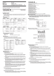
20 mA SINK range
24 V (20 mA) range
Two-wire transmitter
Transformer
Two-wire transmitter
Transformer
+
+
4-20mA
4-20mA
Distributor
CA11E
Lo
Distributor
CA11E
Lo
Hi
Hi
24V DC
■ Output limiter
If a load current in the voltage range or a load voltage in the current range exceeds the maximum
value specified in the specifications, the protective limiter is activated, turning off the output signal.
To recover from this condition, correct the load to normal status and press the [OUTPUT ON/OFF]
key to turn on output.
■ Sweep function
This function increases or decreases the output level to the preset level as a constant rate by
setting DIP switch 1 to ON. For more information, see Subsection 7.1, “Sweep Function.”
6. Measurement
WARNING
● When connecting the device under measurement, turn off the power of the device.
Connecting/disconnecting the lead cables for measurement without turning off the power
of the device under measurement may be extremely dangerous.
● Special care should be taken to avoid connecting a current circuit to the voltage input
terminals or a voltage circuit to the current input terminals. Inadvertent connection may
not only cause damage to the circuit or device under measurement and the instrument,
but may also be dangerous to personnel.
● Always use the lead cables supplied with the instrument.
● Maximum allowable voltage between all input/output terminals and ground is 30 V DC.
Any voltage exceeding this level may not only damage the instrument, but also cause
injury to personnel. Never attempt to apply such voltage.
6.2 Measuring DC Voltage and DC Current
<1> Switch the MEASURE/SOURCE selection switch to MEASURE (measurement).
MEASURE lights up on the display unit.
<2> Select the range to be measured using the range selection rotary switch.
• The display unit shows the measurement results and unit. Indication of the measurement results
will be updated approximately every second.
• If an input signal is over range or not measurable, the display unit shows “----.”
• For invalid ranges, terminal-to-terminal connection becomes open, causing the display unit to
show “-nC-” and “OFF.”
■ Input limiter
If voltage is applied to the current input terminals or excessive current is applied to them, the
internal protective circuit is activated, opening the terminal-to-terminal connection and causing the
display unit to show “OFF.”
In this case, check that the connection is correct and press the [INPUT ON] key (= [OUTPUT ON/
OFF] key). This causes the OFF indication to disappear and measurement to resume.
7. Other Features
The following features are available depending on the settings of the DIP switches, which can be
accessed by removing the cover from the back of the instrument.
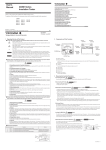
DIP switches
ON
1
2
3
4
1: Sweep function
2: Sweep time (OFF: 16 sec. / ON: 32 sec.)
3: Current display resolution (OFF: 5 digits / ON: 4 digits)
4: Disable automatic power off
7.1 Sweep Function
By setting DIP switch 1 to ON, the output level can be increased or decreased to the preset level at
a constant rate. This function cannot be used in the 24 V (20 mA) range.
Output status transition diagram
Set value
High impedance
Lower range limit
Sweep status
(A)
Operation of
OUTPUT
ON/OFF key
(B)
↑
(C)
(↑)
(D)
(E)
↑
(F)
(A)
(↑)
Operation procedure
<1> Turn on DIP switch 1.
<2> Use DIP switch 2 to select sweeping time (16 or 32 seconds)
<3> Set the MEASURE/SOURCE selection switch to SOURCE. The display unit shows
“SOURCE,” “OFF,” “SP,” and lower limit (initial value).
<4> Use the [▲]/[▼] keys to preset the upper limit for output in the same way as for normal
signal generation (Status A above).
<5> Press the [OUTPUT ON/OFF] key.
(B) The display unit shows “ON” and a lower limit (initial value) for 2 seconds, and the
instrument outputs that value.
(C) Then the reading on the display unit and the output level automatically increase to
the upper limit set in Step <4> at the constant sweep time rate set in Step <2>.
The display unit shows the “ON” light blinking.
In this case, if you press the [OUTPUT ON/OFF] key again, the reading and the
output level will start decreasing from that value at a constant rate. The output status
changes to Status E (shown by dotted-lines in the figure).
(D) When the reading and the output level reach the set values, they remain at these
levels until the [OUTPUT ON/OFF] key is pressed.
The display unit's “ON” light comes on.
In this case, if you press the [OUTPUT ON/OFF] key, the reading and the output
level start decreasing from that value at a constant rate. The output status changes
to Status E.
(E) Then the reading and the output level automatically decrease to the set lower limits
at the constant sweep time rate set in Step <1>.
The display unit shows the “OFF” light blinking.
In this case, if you press the [OUTPUT ON/OFF] key again, the reading and the
output level start increasing from that value at a constant rate.
The output status changes to Status C (shown by dotted-lines in the figure).
(F) Then the reading and the output level reach the lower limits and remain at these
levels for 3 seconds. The display unit's “ON” light comes on.
<6> Return to Step <4>.
Canceling the sweep function
<7> Open the cover at the back of the instrument and set DIP switch 1 to off.
7.2 Switching Display Resolution
By changing the setting of DIP switch 3, the display resolution (5 digit/4 digit) can be selected.
The available ranges are as follows:
SOURCE: 20 mA, 4-20 mA, 24 V (20 mA), 20 mA SINK
MEASURE: 20 mA, (4-20 mA)
<Example 4-20 mA ranges>
5-digit range
4-digit range
CAUTION
● Do not apply voltage exceeding the maximum allowable input voltage to the voltage input
terminals. This may damage the instrument.
Maximum input voltage: 30 V DC
● Do not apply current exceeding the maximum allowable input current to the current input
terminals. If current exceeding this level is applied, built-in fuses for protecting the
current input circuit will burn out. If a fuse burns out, contact us for repair.
Maximum input current: 24 mA
7.3 Disabling Automatic Power Off
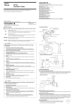
6.1 Connecting Procedure
<1> Insert the plugs of the supplied lead cables into the terminals of the CA11E as shown in figure
“a” below for voltage or in figure “b” below for current.
<2> Connect the clips on the other ends to the input terminals of the device under measurement.
a. Connection of the
voltage input terminals
According to the factory setting of the instrument, it automatically turns itself off if not operated for
about 10 minutes. By setting DIP switch 4 to “ON,” this function can be disabled.
However, when the instrument is battery-driven, it is generally recommended that this switch be
set to “OFF” in order to prevent the batteries from being exhausted.
b. Connection of the
current input terminals
INPUT V
INPUT mA
Hi
Lo
+
-
Hi
Hi
Lo
Hi
-
+
IM CA11E-01E <2>