1
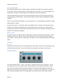
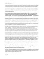
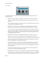
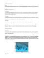
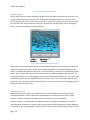
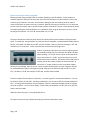
nuSpin User’s Manual nuSpin User’s Manual Contents Welcome to nuSpin! ................................................................................................................................. 2 Overview ................................................................................................................................................... 2 Getting Started.......................................................................................................................................... 3 Locate Your Product Code. ................................................................................................................... 3 Sign up for your nuSpin account. .......................................................................................................... 3 Confirm your nuSpin account................................................................................................................ 3 Enter your Feature Code. ...................................................................................................................... 3 Performance View Navigation .................................................................................................................. 4 Menus ................................................................................................................................................... 4 Controls ................................................................................................................................................. 5 Working with Programs ............................................................................................................................ 6 Overview ............................................................................................................................................... 6 Synth Tab .............................................................................................................................................. 7 Envelopes Tab ..................................................................................................................................... 12 Effects Tab ........................................................................................................................................... 15 Modulation Tab................................................................................................................................... 17 Metadata Tab ...................................................................................................................................... 18 Working with Wavetables....................................................................................................................... 19 Wavetables in nuSpin.......................................................................................................................... 19 How an Image Turns Into a Sound ...................................................................................................... 19 Wave Table Tab................................................................................................................................... 20 Options Tab ......................................................................................................................................... 27 Page | 1 nuSpin User’s Manual Metadata tab ...................................................................................................................................... 27 Appendix A: Examples............................................................................................................................. 27 How to create a classic analog synth program. .................................................................................. 27 How to create a percussive program. ................................................................................................. 28 How to create a plucked string program. ........................................................................................... 29 How to create a wobble bass program. .............................................................................................. 30 Using an existing sound to create a new sound! ................................................................................ 31 Appendix B: Control Names .................................................................................................................... 34 Welcome to nuSpin! Thank you for your purchase of the very first version of nuSpin! We have built a lot into this software that we hope you will explore and enjoy for many years to come. Our mission is to help musicians like you produce fresh new sounds. This document is only the beginning of the information that is available to help you make fresh new sounds on your new VST Instrument – please check us out online at http://www.nuvibrations.com and on the nuVibrations YouTube channel. Overview nuSpin takes a fresh approach to synthesizer design by presenting two interfaces. The first and primary interface is the performance view. The performance view is designed to be where people play their sounds in some type of performance capacity. This may be live on stage or creating music in your favorite DAW software. In performance view we have tried to eliminate anything that would distract you from thinking like a musician and being in your creative zone. But there will be times when musicians will want to tinker with a sound, or carve up an entirely new sound, and that is where the edit view comes into play. In edit view, you are not only designing a sound, you are designing the performance interface for that sound through the parameter controls you choose to expose and the names you give to those controls. Page | 2 nuSpin User’s Manual Getting Started Locate Your Product Code. A 16-character product code should have been provided when you obtained the software. The code will have the following format: XXXX-XXXX-XXXX-XXXX Where the X’s are characters. If you do not have a product code, please visit http://www.nuvibrations.com to obtain one. Once you have located your product code you are ready for the next step: Load nuSpin in your favorite synthesizer host software and open the window for nuSpin. The first time you open nuSpin, you should be prompted to register your software. Click the register button, and that will bring up the login dialog. If you have run nuSpin before, you can still register by using the menu button. Select “Enter Feature Code” under “Media” from the menu arrow button. The menu button looks like this: Sign up for your nuSpin account. If you have never created a login account for nuSpin before, you will need to click on the “Sign Up” Link in the upper right corner to create an account. You will be prompted to enter the information required to set up an account. Enter all the information, then press “OK” to move to the next step. Confirm your nuSpin account. If the information was successfully submitted, then you will get a notification that an e-mail was sent your e-mail account. Check your e-mail box for the confirmation e-mail and the remaining instructions required to set up your account. Once your sign up is complete, you can log in. If an update is needed. If an update is available, you will be prompted to begin the process to download and install it. Enter your Feature Code. Once you are logged in, you will be prompted to enter your feature code. Enter just the characters without then press “Ok”. Once the process completes, all your features and media should be ready to use! Page | 3 nuSpin User’s Manual Performance View Navigation The purpose of the performance view is to load, play and control programs. In order to play a program, you first have to load it into memory. Menus The main menu button in the upper-left corner of the performance view is where you can control the registration, loading, creating, and editing of media in nuSpin. Click the menu button once to open the menu. Media Inside the media menu you will find three options: Enter Feature Code Whenever you have installed or updated your software or media, you need to enter the accompanying feature code in order to unlock access to the new media and features. Make sure you are connected to the internet before you attempt to enter a feature code. If you have not logged in, you will be prompted to log in before entering your code. Check for Updates Use this option to check for important software and media updates. Compact Local Data nuSpin saves your data in a file in your document folder. From time to time this data file may need to be compacted in order to purge data you are no longer using. It is recommended that you use this feature once for every 8-hours of sound creation work. Load This is where you can choose to load programs into memory for later playback. When you select this item, a larger menu opens up showing the programs that are installed on your system. Simply click on the program you want to load out of this list and it will be loaded at the end of the current list of programs. Create You get two options here: “Program” or “Wavetable”. Selecting “Program” will open the program editor with a simple program set up. “Wavetable” will open the wavetable creation editor, and you will need to load a piece of media (image or WAV) into the “Input Image” window to hear any output. Creating Wave tables is discussed further in the Working with Wavetables section. Edit “Program” or “Wavetable” are your two choices. This opens an existing program or wavetable for editing. Page | 4 nuSpin User’s Manual Controls Parameter Knobs The four knobs (some of which may be grey depending on what program is currently active) allow you to control the sound that the active program makes when a note is active. The function of each control changes depending on which program is active. For a description of the control types, see Appendix B, +/- buttons The +/- buttons provide a quick way to move between loaded programs. Pressing “+” activates the next highest-numbered program. “-“ changes to the next lowest program. Pressing “+” when at the last program will activate the first program. When at the first program, pressing “-“ will activate the last program. Program Information Pane The blue Liquid-Crystal display area is where you can access information about the current active program. Current Program The program number is displayed in the upper left, followed by the program name of the active program. Below that, comments and information about the active program are visible. To the right of the program name, there are upto three buttons, depending on what media has been loaded. Program selection menu If you have more than one program loaded, you will see an arrow button. This button brings up a menu that will allow you to activate any of the loaded programs. Page | 5 nuSpin User’s Manual Edit button If the active program was saved with its creation data, you will see an “edit” button. This button will bring up the program editor for the active program. For more about editing programs, see the Working with Programs section. Unload button Pressing “Unload” will unload the active program, and activate the next nearest program in the list. nuVibrations button The nuVibrations button (purple logo with a “nu” in the center) connects you with nuVibrations on the web, where you can keep track of the latest nuSpin news and releases of sound sets. Working with Programs Overview We’ve packed a ton of great features and flexibility into nuSpin, so if this is your first time reviewing the manual, it may take a while to sink in. If you are a more experienced user, you might want to jump straight to the examples in Appendix A. Fundamental concepts Every control can be modulated (except for the ADSRs). You can edit modulation quickly by using a module’s modulation menu, or you can edit modulation on the modulation tab. Overall Signal Path nuSpin programs have three sections: 1) The 4 global Low Frequency Oscillators (or LFO’s) that can be used to modulate any other parameter. In addition to the LFO’s, incoming MIDI data and parameter control changes are available to modulate any other parameter. 2) The per-note modules that include the overall envelope, four additional LFO’s two additional ADSR envelopes, three oscillator modules, and two filters. 3) The effects section that takes the sum of the per-note processing and provides 5 more filters, two distortion modules, an echo, and a reverb. Page | 6 nuSpin User’s Manual Per-note Signal Path All waveforms originate with an oscillator module. By default, the output of an oscillator is routed to the envelope. But you can also choose to route through one or both filters. You can also engage a ring modulator to multiply the oscillator signal into the destination rather than adding it in. Lower numbered oscillator outputs can be used to modulate a higher-numbered oscillator parameter – including the pitch of the oscillator. This provides the ability to create Frequency Modulation Synthesis programs. Filter 1 can be routed to the envelope, or it can route to filter 2. This provides both a serial filter routing, and parallel filter routing. One of the filter types is a comb filter, which has a feedback control. Using the comb filter with a high feedback and a frequency modulated by the incoming MIDI note value allows you to create plucked string programs. We have also created a special one-shot oscillator sync mode that is the perfect way to stimulate a comb filter with feedback. Effects Section The effects section is arranged so you can easily create a variety of classic guitar amp sounds, or create something entirely new. The echo delay can be modulated by an LFO to provide phasing, flanging, or chorus effects. The final effect is a reverb, which once again, can be modulated to provide some unique effects. Synth Tab Overview The Synth tab is where the sound of a program begins to take shape. nuSpin’s core synth features three oscillator modules, two filters, an overall envelope, and a polyphonic/monophonic mode control. Oscillator Modules An oscillator (labeled “OSC 1”, “OSC 2”, and “OSC 3”) is where all sound you hear originates. The first blue combo box on the left is where you set up the waveform that the oscillator will produce. When you create a new program (from the Create->Program menu) each oscillator defaults to producing a square wave, so the name in the combo will be “Square”. You have 5 classic waveforms to choose from, and a range of wavetables that will vary depending on what media you have purchased or created. Page | 7 nuSpin User’s Manual If you open the waveform combo menu and select the “SawTriSaw” wave table, you will see the combo on the right activate. This box controls how the waveform is played. By default, “One-Shot” mode is selected, which means the entire wave table plays over 5 seconds. You can also select “Controlled” in the waveform combo which will also activate the “Wave Pos” knob that allows you to select which part of the waveform will play. Remember, just about everything can be modulated in nuSpin, and that includes the wave position. You can set up a different playback rate for the wave table by adding “ADSR 1” as modulator to the “Wave Pos”. To do this, click the oscillator’s menu button, then select “WavePos->Add Modulator>Program->ADSR 1” and now you can control the wavetable position with the ADSR! And now think of what is possible with the rest of the available modulation sources! Oscillators also have a tuning control (center knob for cents, outside ring for semitones), a pan control, and an overall gain. And yes, all of these can be modulated too! By default, the tuning is controlled by a combination of the MIDI note value, the active MIDI portamento settings, and a synth-global pitch modulation LFO. You can turn off the default tuning control by using the oscillator’s menu button to select “Note Tracking->Off” with Note Tracking turned off, the oscillators pitch is set only by the tuning control (and whatever modulation is feeding the tuning control). You might have noticed the “Oscillator Sync” options in the menu – these control how the waveform is played. The default, “Free Running” simulates a free running analog oscillator, whose phase is continuously updating even when the note is not being played. This provides for very organic and evolving analog synth sounds. If you would rather produce the same sound every time you activate a note, you can use the “Sync to Note Start” option, which always sets the phase of the wave to zero when playback starts. The last option in this menu is especially designed to be used with plucked string simulation using comb filters, and it is called “one-shot”. In this mode, a single period of the waveform is played, starting at the first zero crossing (to avoid clicks), and then the oscillator is silent thereafter. So where does the output of the oscillator go? The routing of the oscillator is controlled by the number buttons along the left side of each oscillator. With no number buttons pressed, the output of the oscillator is routed directly to the Envelope, with no filtering applied. When you press the “1” button, the oscillator’s output is routed to Filter 1. When you press “2”, the oscillator’s output goes to filter 2. And when you press both “1” and “2”, you send half the signal to filter 1, and the other half to filter 2. This routing allows you to create both serial and parallel filter configurations for some great vocal-tractlike effects, or classic subtractive sounds. Finally, there is the “*” button. By default, the oscillator’s output is added into the signal of the destination. When “*” is pressed, the signal is multiplied into the sum of the signals feeding the destination, providing the option of ring-modulation effects. One more note about modulation sources, the output of oscillator 1 can feed any control on oscillator 2 or oscillator 3. The output of oscillator 2 can feed any control on oscillator 3. This means you can use nuSpin to explore some basic FM synthesis. Enjoy! Page | 8 nuSpin User’s Manual Filter Modules The modules labeled “FILT 1” and “FILT 2” on the synth tab control audio filtering settings. Filters provide 9 basic types: Bypassed – the filter is bypassed. Any signal sent to the filter is sent directly to the output without any processing. No knob or modulation settings are active when the filter is set to bypassed.. This is the option to use when you do not need a filter. Using “Bypassed” ensures that none of your computer’s processing power is wasted. Lowpass (2-Pole) – The filter acts as a lowpass filter with a gradual transition at the cutoff frequency. A “Frequency” knob is activated that controls the cutoff frequency of the filter. This is most useful for rolling off unwanted high frequencies gradually. When the frequency is modulated, the 2-pole lowpass filter produces somewhat less noticeable filtering compared to the 4-pole, making it a good choice for modulating with an ADSR in order to produce naturalsounding high frequency attenuation. Lowpass (4-Pole) – The filter acts as a lowpass filter with a sharp transition at the cutoff frequency. A “Frequency” knob is activated that controls the cutoff frequency of the filter. This is a great choice for creating a wobble-bass when it is modulated by an LFO that is synced to the beat. The 4-pole filter has a sharp transition that makes it very noticeable. This filter can also be used for aggressively rolling off high frequencies. Lowpass (Resonant 4-Pole) – The filter acts as a lowpass filter with resonance at the cutoff frequency. A “Frequency” knob is activated that controls the cutoff frequency of the filter. A “Resonance” knob is also activated, which controls the amount of ringing that is generated at the cutoff frequency. The Resonant 4-Pole lowpass can produce a classic analog synth sound with the resonance cranked up and the frequency modulated by an ADSR. Band Shelf (2-Pole) – The filter acts as a band shelf with a gradual transition at the band edges. A “Frequency” knob is activated that controls the center frequency of the filter. A “Bandwidth” knob is activated that controls the width of the shelf around the center frequency. A “Gain” Page | 9 nuSpin User’s Manual knob is activated that controls the amount of boost or cut that is applied in the shelf range of the filter. When you need a gentle nudge of a frequency band, the 2-pole band shelf is ready for the job! Band Shelf (4-Pole) – The filter acts as a band shelf with a sharp transition at the band edges. A “Frequency” knob is activated that controls the center frequency of the filter. A “Bandwidth” knob is activated that controls the width of the shelf around the center frequency. A “Gain” knob is activated that controls the amount of boost or cut that is applied in the shelf range of the filter. This filter is great for adding some bite to a distorted synth program by using a narrow bandwidth and a high gain in the 1000-3000 Hz frequency range. Highpass (2-Pole) – The filter acts as a highpass filter with a gradual transition at the cutoff frequency. A “Frequency” knob is activated that controls the cutoff frequency of the filter. The 2-pole highpass is great at taming a program with too much bottom end while still producing a natural-sounding result. Highpass (4-Pole) – The filter acts as a highpass filter with a sharp transition at the cutoff frequency. A “Frequency” knob is activated that controls the cutoff frequency of the filter. Modulating the frequency of the 4-pole highpass can produce some interesting effects. This filter also works great for eliminating subsonic frequencies below 20Hz. Comb – this is micro delay with mix and feedback controls. The “Frequency” knob provides control over the fundamental frequency that the comb filter will reinforce. The “Mix” knob allows you to control how much of the dry versus wet signal will be output. The “Feedback” knob controls how much of the wet output is fed back into the input of the delay. If you want to create a comb filter that reinforces the MIDI note frequency, set the frequency knob to full left (20.0 Hz) and then modulate the frequency control with the MIDI note. This is a great way to create plucked string sounds – use a high (more than 80%) feedback setting for this. Also make sure your Envelope setting doesn’t stomp on the natural comb filter envelope. Page | 10 nuSpin User’s Manual Envelope Module The Envelope Module on the synth tab controls an envelope generator with 4 stages: Attack, Decay, Sustain, and Release – or ADSR for short. These stages simulate the envelope of natural instruments which generally follow a pattern where a note activation produces a ramp-up of intensity, followed by a slight decay, followed by a period of constant sound level, followed by an exponential decay when the note is released. In the Envelope Module, the gain at the start is -infinity dB, and ramps up to 0 dB over a controllable period of time. The ramp up time is controlled by the center wheel on the “attack” knob, with attack time being variable between ½ a millisecond and 10 seconds. The outer wheel on the “attack” knob controls the shape of the attack of the curve. The default position of the outer attack knob is at 7.5 ticks which produces a fast attack (lots of change at the start, and flattening out at the end of the attack. When the outer-knob is set to full left or full right, you produce a smooth curve (slow at the start and end, with most of the change in the middle). At a setting of 2 ½ ticks from full left, you get a slow curve (slow at the start, fast at the end). When the outer knob is straight up, you get a linear curve, with a constant rate of change during the full attack. Settings in between produce a blend of curves, which gives to a lot of room to play! The “Decay” knob controls the amount of time it takes for the envelope to drop from 0 dB to the sustain level. Like the attack knob, you can control both the time and the shape of the curve. The “Sustain” knob controls the level when a note is held. This can range from -infinity dB, to 0 dB. Finally, the “Release” knob controls the duration and shape of the release curve, and works in the same way that the attack and decay knob works. Page | 11 nuSpin User’s Manual Mode Module The Mode module is where you can control whether the program is polyphonic (multiple notes at the same time) or monophonic (one note at a time, with optional portamento), and how portamento is applied. The top combo box sets the poly/mono mode. In polyphonic mode, the other controls in the box are disabled. When you select Monophonic mode, you get access to two more combo boxes and a knob. The second combo box from the top controls how and whether notes are retriggered. The default setting is “Recover”, which mean that if you play a note, then release it, but strike another note before the first has fully decayed, the amplitude will quickly recover back to the sustain level and stay there until the second note is released. “Legato” note triggering means once a note is triggered, the normal envelope curve will be applied even if a second note is triggered. This is handy for simulating hammer-ons or pull-offs on guitar programs. Finally, “retrigger” note triggering causes the note (envelope plus wavetable) to be completely restarted every time a new note is pressed. The bottom combo box in the mode module controls how the portamento works. In “Continuous” mode, the pitch smoothly transitions from the first note value to the second. “Quantized” mode caused the pitch to move in half-steps, like you were running your finger up the fretboard of a guitar. Quantized mode works best with longer portamento time settings. Speaking of portamento time settings, as you have probably guessed, the knob in the mode module allows you to set the portamento time. Portamento time describes how long it will take for a note to glide from the starting pitch to the ending pitch. This knob can be set to any value between 10 milliseconds and 1 second. Envelopes Tab Overview The Envelopes tab allows you to control a number of modulation sources that can be used to modulate controls elsewhere in the synth. These are really the workhorses of your synth sound, giving you the ability to craft evolving and interesting sound textures. Page | 12 nuSpin User’s Manual Global LFOs (LFO 1-4) The first four Low Frequency Oscillators (or LFO’s) can be used to modulate any other parameter in the synthesizer, and are great for coordinating modulation between the synth and the effects sections. A low frequency oscillator produces a relatively slow changing signal. The frequency of an LFO ranges from 0.1 to 100 Hz (or cycles per second), and is controlled by the inner “Frequency” knob. The outer knob controls the starting phase of the oscillator. The “Gain” knob controls the output level of the LFO, and ranges from -infinity to 0 dB. By default, all LFOs are set to “off”, but by clicking the blue combo box, you can select from a number of waveforms including: “Square”, “Triangle”, “Sine”, “Saw”, “Inverted Saw”, “Noise” and “Random”. Each type of waveform has its particular characteristics and uses as outlined below: “Square” – This waveform begins at full positive signal at 0 dB, and drops to full negative signal at 0dB and repeats. “Triangle” – the waveform starts at -infinity dB and ramps up to 0 dB (full positive), then ramps down to full negative, and back to -infinity dB. “Sine” – the waveform starts at -infinity dB, and moves up to full positive along a sine wave. “Saw” – the waveform starts at full positive, then travels to full negative, then jumps back to full positive. “Inverted Saw” - the waveform starts at full negative, then travels to full positive, then jumps back to full negative. “Noise” – produces a random waveform with a dominant frequency at the LFO’s “frequency” setting. “Random” – produces a stepped random value that changes at the same frequency as the LFO’s “frequency” setting. If you crack open the menu button for a global LFO module, the first thing you will see is a “sync” setting. “Sync” controls how the frequency is expressed. In “Sync to play start” mode, the waveform plays as if it started at time zero and you have continuous control of the frequency. Page | 13 nuSpin User’s Manual In “Sync to Beat”, the LFO is synced to the midi beat/bar position. The frequency controls the musical note duration of one period of the waveform, providing steps from 2 measures, 1 measure, ½ measure, ¼ note, 1/8th note, 1/8th triplets, 1/16th , 1/16th triplets, 1/32nd , 1/32nd 9-tuple, 1/32nd triplets, and 1/64th. This mode makes it easy to create LFO’s that are always synced to the current tempo. Additionally, if you modulate this parameter, transitions from one value to another are only allowed to occur at the start of the waveform. This makes for a very musical way to control an LFO. The “Frequency” and “Gain” menu items allow you to add/remove modulators or show the modulation scale for the controls. Global LFOs can be modulated by the performance controls, MIDI controls, or any global LFO with a lower number. Per-voice LFOs (LFO 5-8) The Per-voice LFOs work pretty much the same way as the global LFOs except they have different sync modes and they can only be used by other per-voice LFOs or items on the synth tab. The sync modes exposed by this module are: “Sync to play start” – works just like the option of the same name for global LFOs. “Sync to note start” – this starts the waveform at zero phase at the time the note is activated. “Frequency” is in Hz. “Sync to beat” – works just lke the option of the same name for global LFOs. Per-voice LFOs can be modulated by performance controls, MIDI controls , any LFO with a lower number and ADSR 1 and ADSR 2. Page | 14 nuSpin User’s Manual ADSRs The ADSR modules in the envelopes tab work just like the envelope in the synth tab with one addition: ADSRs also expose a gain control that allow you to scale the output of the ADSR. Effects Tab Overview The effects tab is where you can control the effects of a program. The effects (5 filters and two distortions) are arranged to give you the ability to simulate a number of guitar amplifier models, with a final echo and reverb. All controls on the effects tab can be modulated by Parameter Knobs, MIDI input, or the Global LFOs. Distortion Modules In nuSpin, a distortion module is a wave shaper with four modes: “Bypassed” – deactivates the distortion. “Soft Clip” – applies a smooth transfer curve to the input that produces a less harsh clip than the other modes. “Soft Clip” can be used to “warm” up a signal as well as distort it. “Medium Clip” – this mode has a slightly smooth transition from normal to clipped, and maintains close to a unity gain for most of the input range. “Hard Clip” – the mode ensures the signal never exceeds 0dB and applies no gain when the input is lower than 0 dB. In addition to the mode combo box, there are three controls: Page | 15 nuSpin User’s Manual “Gain” – controls the amount of gain applied to the input signal before it is sent to the wave shaper. “Wet/Dry” – controls the mix of effected/unaffected signal sent the the output. “Volume” – controls the output level of the effect. Echo Module The Echo Module provides various types of echo. The combo box sets the basic delay range of the module: “Bypassed” – turns off the effect. “Micro (.0-50mS)” – produces very short delays that are useful for comb filtering and phasing. “Short (25-150mS)” – produces delays that are useful for flanging or chorusing, or simple thickening. “Medium (.1-1 S)” – produces a range of slap-back delays. “Long (0.5-10 S)” – produces canyon-like echo. All modes except bypassed expose three knobs: Delay, Mix, and Feedback. “Delay” sets the delay of the module within the range set by the mode. “Mix” controls the percentage of wet/dry signal that is sent to the output. “Feedback” controls how much of the delay output is mixed back into the delay input. This controls the number of echoes that are audible. The most powerful use of modulation is to modulate the delay with an LFO. Using this technique, you can turn the echo into a phaser, flanger, or chorus effect. Of course, you are also free to experiment with modulating the “Mix” and “Feedback” controls as well. Reverb Module Page | 16 nuSpin User’s Manual The last module on the Effects tab is the reverb module labelled “REV 1”. The reverb module provides five modes via the blue combo box: “Bypassed” – no effect is applied. “Room” – a full bandwidth reverb. “Room (Bright)” – reverb with the low frequency reflections attenuated. “Room (Midrange)” – reverb with the low and high frequencies attenuated. “Room (Dark)” – reverb with the high frequency reflections attenuated. The reverb module has three controls: “Decay” – this controls how long the reverb will take to decay, with ranges from 500 milliseconds to 10 seconds. “Mix” – controls how much of the wet versus dry signal is sent to the output. “Volume” – adjusts the final output level of the reverb. Modulation Tab Overview The modulation tab allows you to view and edit modulation settings across the entire signal chain, making it a great place to track down problems or understand the big picture signal path. The page provides a list of modules in the synth to view, and a list of parameters for each module. You can quickly see which modules have modulation by checking the module name for a number in parenthesis “()”. the number in the parenthesis indicates how many modulation sources are feeding that module. Likewise, the Modulation Target list also shows you how many modulation sources are feeding each target. Once you have selected a Module and Modulation Target, a number of other controls appear: The “Modulation” knob – this knob adjusts the scaling factor applied to the modulation that is feeding the target control. It can range from -1.0 to 1.0, giving you the ability to invert and scale the input. Under the first row of controls will be a list of active modulators for the selected modulation target. For each item in the list, there will be an “X” button that allows you to delete a modulator, a source combo box that allows you to change the modulation source, and a knob that allows you to scale the amount of Page | 17 nuSpin User’s Manual that modulation source that is sent to the modulation target. The per-source knob on the modulation tab is the only way you can adjust per-source modulation. At the bottom of the list of modulation sources, there is a “+” button that allows you to add a new modulator. Pressing this button will bring up a menu with a list of all the available modulation sources that are allowed to feed the modulation target. Metadata Tab Overview The last tab in the program editor allows you to configure the various label and category settings that will make it easier to use your new program in performance mode. Text Fields “Short Name” is the name that will appear in your VST host when it displays the name of the current program. “Long Name” is the name that will appear in nuSpin when you are working with a program. “Description” is intended to be used for special instructions for using the program, and copyright notices. By default, a copyright symbol and the current year number are added to this text field when you create a new program. Category Combo “Category” this is the category field that your VST host can enable to assist in navigating plug-in programs. Control Labels There are also four “Control” boxes which are used to assign names to the four parameter controls. Be aware that the parameter control knobs will not activate until you use one of their outputs to modulate a control on the synth. Also be aware that knobs will activate from left to right. So if you only use control D, all the knobs will activate. The intention here is that if you use three or less knobs, you should assign them from left to right, and leave space at the right. Page | 18 nuSpin User’s Manual Anyway, once you have set up a knob to modulate something, the knob will be active and you can see the knob name under the knob. Knobs default to “<unassigned>”. Please find the closest name that fits how the knob is supposed to be used when playing the synth. You can find a list of available control names and their intended uses in Appendix B: Control Names. Working with Wavetables Wavetables in nuSpin Wavetables in nuSpin are created by scanning an image in the Image Editor. nuSpin comes packed with many existing wavetables that you can modify to create your own wavetables. You can also import your own images and WAV files to convert into sound. How an Image Turns Into a Sound Wave Terrain Synthesis The basis for nuSpin’s image-to-sound conversion process is called Wave Terrain Synthesis. This method of synthesis creates a waveform by tracing a path along a surface and using the altitude along that path to generate an output signal. In the case of images, the surface altitude is defined by the brightness of the pixels in an image. You can think of the process like that of a phonograph player playing a vinyl record: A needle travels along the surface of a record and the altitude of the needle at any given instant determines the output signal. Now imagine an image was etched into a phonograph record and you were free to set the path of the needle. A phonograph player plays at a fixed speed (usually 33 1/3 RPM). When you play a phonograph at a different rate, the pitch of the sound changes too. Since a software synthesizer needs to play a range of pitches, the speed of our virtual phonograph player is controlled by the pitch of the note being played on a keyboard. If you want to play an A-440, the image will be scanned at a rate of 440 cycles per second. As a waveform continues playing, changes in the radius and offset of the scan path over time produce an evolving waveform. This is what makes a sound come alive. Page | 19 nuSpin User’s Manual Wave Table Tab The Wave table tab is where you load images or sounds, and refine the results. When you create a wavetable, you are presented with a screen with a blank image and no harmonic spectrum. The first step is to click the “Open…” button and select some images or sounds to use as a basis for your new wavetable. Once an image is loaded, nuSpin goes to work creating a wavetable and spectrum. This may take a few seconds depending on the size of the image. Description of Controls Image Scan Section Opening Images The “Open” button is used to select images (or sounds) to load into the image browser. This button brings up an open file dialog where you can select one or more images to load. Page | 20 nuSpin User’s Manual Figure 1: The Open Dialog Special Settings for opening Sounds. If you open a WAV file, you will be asked to enter the pitch of the note in that file. nuSpin tries to guess the pitch based on the location of zero-crossings in the waveform and will pre-fill the controls with that guess: The note and octave describe the MIDI note number, where middle “C” is C4. The cents field is used to fine tune the pitch. If everything goes correctly, most sounds converted to images will look like a radial pattern. If the pitch of the sound was different from what you entered, you will get a more randomlooking image. When you load sounds, the orbit and harmonic controls are automatically adjusted to play the new sound as a one-shot with no changes. There are also two settings on the options tab that are disabled in Page | 21 nuSpin User’s Manual order to preserve the original sound quality: “Remove DC Offset” and “Align phase of harmonics” There is more information on how these settings work in the How an Image Turns Into a Sound section. Image Navigation Once you have loaded images into nuSpin, you can select the active image by pressing the left and right arrow buttons. Horizontal & Vertical Position The horizontal and vertical knob controls position the center of the scan path over the image. This is used to place the scan path over a part of the image you are interested in. Figure 2: Default position, horizontal shift, vertical shift. Scan Eccentricity & Angle You can think of eccentricity as how much the scan path is shaped like an oval rather than like a circle. A higher eccentricity setting produces a greater ratio of the width of the scan path to the height. At full eccentricity, the scan path becomes a line. Use the Angle control to rotate the oval to align with interesting features in the image. Figure 5: No eccentricity, some eccentricity, eccentricity with some rotation Page | 22 nuSpin User’s Manual Scale The scale sets the radius of the scan path. The scale ranges from zero to 100 percent of the size of the image. Harmonic Control Section Smoothing The smoothing knob spreads out harmonics over time. In the spectrum image you will see the image blur horizontally. Smoothing can be set to zero, with no harmonic blurring, up to spreading out the harmonics over the entire range. Expansion Expansion brings out the most prominent frequencies of an image scan path. In the spectrum window, this appears as increasing contrast in the frequency spectrum. Low Filter The Low Filter is used to adjust the relative levels of the first few harmonics compared to the overall volume. This can be used to cut or boost the fundamental to balance the overall tone. Low Pass The low pass harmonic frequency causes harmonics above a set range to be eliminated from the waveform. This can be used to remove the shrillness from a sound or to carve out an undesirable spectral component. Normalize The normalize knob is used to balance out the volume of the waveform over time. Some of the other controls can create a sound with an uneven volume. If this is not desirable, you can use this control to balance the volume level. Spectrum Window The Spectrum Window displays the harmonics of your waveform over time. The vertical axis represents frequency. The bottom is the fundamental, and the top is this highest harmonic. The left part of the image shows the start of the spectrum and the right part shows the end. Lighter parts reflect a stronger harmonic at a particular time. Page | 23 nuSpin User’s Manual Figure 6: Spectrum window with labels Key frame Control The key frame control is used to automate changes to scan path and harmonic controls over time. This is used to allow sounds to evolve over time. Just below the spectrum window you will see a round horizontal fader knob. Think of this as the time control. Parts of the sound that occur earlier are to the left, and later parts of the sound are on the right. By placing the horizontal knob you are setting the point in time where changes to knobs will be made. Figure 7: Output Spectrum with Key Frame control When you have the time knob set somewhere in the middle of the range and you adjust a knob on the harmonic or image scan window, you will see a blue diamond appear in the window below the time control. This diamond represents a key frame. A key frame tells you that there is a knob setting at that point in time. You can now move the key frame to the left and right by dragging with the mouse. By moving the key frame, you are changing the point in time that the knob setting occurs. This can be used to carefully align your control changes with a specific point in time. You can also add a new key frame by clicking on an open space in the key frame window. You can remove a key frame by dragging the key frame up or down with the mouse. Sculpting the Sound Applying wave terrain synthesis to an image opens up a lot of possibilities, but once you have an interesting waveform, it often needs to be manipulated a bit to produce a musical result. nuSpin provides a number of ways of sculpting the harmonic content of your new waveform. Since the content in an image under a changing scan path can change dramatically, this can result in rapid changes in the harmonic content of the resulting waveform that can sound like random bleeping. In some cases, this may be desirable. At other times this may produce too distracting a sound if you are Page | 24 nuSpin User’s Manual creating a waveform to be used for a pad. nuSpin allows you to blur the changes in harmonic content over time to get a more organic-sounding result. Figure 8 No blur, medium blur, and maximum blur. Harmonic Expansion The character of a waveform is defined by the ratio of harmonics within the waveform to one another. Image scans often produce a very broad and flat set of harmonics that can lack character. To bring out the character in a waveform, nuSpin has a harmonic expansion control. The harmonic expansion control amplifies the relative differences between harmonics to deliver more character. High levels of expansion can produce very ringy sounds, while low levels produce buzzy sounds. Figure 9: Low, Medium, and High levels of harmonic expansion. Low Boost Once you have smoothed your sound and brought out the perfect degree of character, you may find there is too much or too little of the fundamental harmonic in your sound. The low boost control can be used to balance the level of the fundamental with the overall sound. Low Pass Harmonic Filter nuSpin also features a low pass harmonic filter that reduces the level of harmonics above a user-defined frequency. This can be used take excessive brightness out of a waveform, or to create a naturalsounding decay in higher harmonics. Amplitude Normalization Sometimes as an image-generated sound evolves, the amplitude can change in a non-musical way. You can use the normalize control to adjust the consistency of the amplitude of the sound is over time. Page | 25 nuSpin User’s Manual Changes Over Time Speaking of changes over time, the final control is the key frame control. With the key frame control, you can cause any of the parameters of sound creation (path or harmonic) to change over time. How to Make Great Waveforms. Determine what kind of sound you want to make. As in most areas of art, having a good idea of what you want to accomplish is often the best place to start. Start with a great image What does a great image look like? It depends on what you want to accomplish. The key is to understand how different types of images are likely to sound. The basic rule is the more complex detail there is in an image, the more high harmonics will be present and the more buzzy the result will sound. Images with lots of complex detail don’t produce much variety in how they sound, so try to find images with simplicity. Images with sharp contrasts produce bright waveforms. Images with smooth gradients tend to sound more like a sine wave. Selecting a great scan path Now that you have an image to start with, how do you want your sound to begin? Should it be buzzy? bassy? tinny? To create a pure tone, look for a place in the image with a light to dark gradient and craft a scan path to cross through the full range of that gradient. A tinny sound can be found in a part of an image with a regular pattern. Parts of an image that contain randomness sound buzzy. When you think of the kind of sound you want to produce, does it have a lot of change over time or a little? How does it change? Larger changes in the scan path produce more dramatic changes in the sound texture. So if you want a fairly constant sound, you should set up very subtle changes in the scan path. If you want a rapidly evolving sound, try a scan path with more change. As a scan path changes, it picks up content from the part of the image it is passing over. Do you want a sound to become buzzier? Find a part of the image to scan over that has randomness. Do you want your sound too evolve to a pure tone? Look for an area where you can scan a gradient. Does your sound need to become tinny? Scan over a part of the image with a repeating pattern. Polish the sound with harmonic controls. Once you have mastered the technique of crafting a scan path to exploit the best an image has to offer, you are ready to bring out the best elements of what you have got. Is there a bit too much harmonic change in a short period of time? Try increasing the smoothing. Does the sound need a little more harmonic character? It might be good to crank up the expansion. Is it hard to hear the higher harmonics? Try cutting the low harmonics with the low shelf filter. Is there way too might high end? Turn down the frequency on the low pass control What’s Next? Once you have finished setting up your image scan wavetable, you can use the metadata tab to name your creation. Then you can save it and put your wave table to work in a new synth program! Page | 26 nuSpin User’s Manual Options Tab The options tab contains two checkboxes that enable or disable two features during the image scanning process. “Remove DC offset” ensures that the average level of one period of the waveform is always zero. This feature can prevent unwanted popping when scanning images. “Align phase of harmonics” is used to prevent dropouts of frequencies due to changes in phase caused by the scan path automation. Phases of all frequencies are aligned at zero degrees to prevent this problem. These two features are most useful (but not always) for scanning images, and tend to cause problems when scanning an image generated from a wave. Therefore, these options default to active when an image is loaded, and off otherwise. Metadata tab The last tab on the wavetable editor is the Metadata tab. It contains the same first three fields as the Program Editor’s metadata tab: Short Name, Long Name, and Description. The Long Name is used in the program editor’s oscillator source menus. The description field can be used to notate where you obtained the image from, and any special instructions about how you created the sound. Appendix A: Examples How to create a classic analog synth program. In this example we will create a classic sawtooth synth program, a resonant filter, and some other effects. First, create a new program (Main Menu->Create->Program) and set all the oscillators to use the “Saw” waveform. Set the tune parameter on OSC 2 and OSC 3 to -0.07 and 0.07 semis respectively. And set all the pan controls to center (ctrl+click to auto-center). Give it a play and see what it sounds like… Seems a bit flat, don’t you think? So let’s add some character! From the FILT 1 module, select “Lowpass (Resonant 4-Pole)” from the LCD combo menu. Hmm, now that got really flat. What we need is a changing filter frequency, so go to the menu button and select “Frequency->Program->ADSR 1”. Now on the “Envelopes” tab , dial up the attack time to 169.8 mS, and pull the sustain down to -9.0 dB. And now give it a listen! Ok, much better. Perhaps a bit more? Go back to the synth tab and from the “FILT 1” menu, select “Resonance->Add Modulator->Performance->Control A”, and dial the resonance setting on “FILT 1” to zero, Now give your program a try, while tweaking the newly enabled performance control knob at the top. For a final touch, flip over to the “Effects” Tab and select “Short (25-150 mS)” from the Echo 1 module and dial up the delay time to 100 mS. And select “Room (Dark)” from the REV 1 Module’s combo box. Page | 27 nuSpin User’s Manual How to create a percussive program. Most percussive programs begin with an oscillator producing a fixed frequency. Drums produce a complex frequency spectrum, but there are only have a few oscillators, so take oscillator 1 and 2, and set them up to produce a sine wave. Set the note tracking (via the menu button) to off in order to create a fixed pitch no matter which key is pressed. Now set the tuning of oscillator 1 to -17 semitones (via the outer tune knob), and set up the second oscillator to produce a tone at -12.94 semitones (which will require pulling the outer knob down to -13 semitones, then using the fine tune to arrive at -12.94. Set the gain of oscillator 1 to -11.5 dB, and oscillator 2 to -11.7db. The other component of the kick drum sound is the sound of the kick drum beater striking the drum head. To create that, set up Oscillator 3 to use the “Noise” wavetable, set the playback combo (the left box) to “controlled”, the Wave Pos to 28% Use the oscillator 3 menu to set note tracking to “off” and oscillator sync to “one-shot”. Center-up all the pan controls and try playing a note. It doesn’t sound like a kick drum yet, but we are getting close. You probably noticed that if you hold the note down, the bass keeps rumbling. To fix that, set the sustain on the ENV all the way to a minimum of “-inf dB”, set the attack time to 8.4 mS, and the decay time to 190 mS. The beater sound needs a bit of shaping, but we don’t want to effect the bass oscillators, so unclick the “1” button on OSC 1 and 2 to send their output directly to the envelope, then set up FILT 1 to be a 2-pole band shelf with a center Frequency of 1261 Hz, and bandwidth of 328 Hz, and a gain of 5.0 dB. Now go to the effect tab and set DIST 1 to “Soft Clip”, the Gain to 7.5 dB, the wet/Dry to 94% wet, and the volume to 0dB The basic sound of the bass drum is now there – it is time to give the sound some ambience. First, set the ECHO to “Short (25-150 mS)”, the delay to about 39.1 mS, the mix to 97% dry and the Feedback to zero – this will give the bassdrum a hint of slapback. Now let’s add a fast-decaying reverb to simulate the room response – set up a “Room (Dark)” reverb mode, set the decay to 1.58 S, the mix to 65% dry and the volume to 0dB. What we have at this point is a very deep bass drum. Let’s give it some controls to allow fine tuning the sound in performance mode. Page | 28 nuSpin User’s Manual We have a bit too much low end, so set up filter 4 as “Band Shelf (2-Pole)”, set the frequency to 20.0Hz, the handwidth to 209 Hz, and the gain to -24dB.T We will need to provide some range to change the beater gain, so go back to the synth tab, and on OSC 3, set the gain to “-inf dB”. To speed this up, we will add all the modulation controls from the modulation tab. First, select the OSC 1 Module, and Add “Control A” to modulate the pitch of the bass drum. Do the same thing for OSC 2. To tune the beater pitch, select the OSC 3 Module and set its Tuning to be modulated by “Control C”. Go to OSC 3,s Gain control and set up Control D to modulate it. Now we can control the relative level of the beater. How about some bass control too? Select the FILT 4 Module and the Gain Target, and add Control B to modulate it. So here is what we have set up: Control A controls the Bass drum tuning, Control B controls the level of the bass drum oscillation. Control C controls the beater tuning, and Control D controls the beater level. A good starting position for the controls is: Control A (Bass drum tuning) 11%. Control B (Bass drum level) 77% Control C (Beater Tuning) 43% Control D (Beater Level) 77% If you turn up Control A to 61%, you get a nice conga drum sound. You will find that a whole range of drum types can be created from this sound! How to create a plucked string program. The foundation for a plucked string program is a comb filter with the feedback set close to 100%. A comb filter is basically a very short delay. The delay setting determines the frequencies that will resonate. To start off, we need an initial impulse to stimulate the resonance. Select the create->program item from the main menum, and set up OSC 1 to use the “SawTriSaw” wavetable. Select the Oscillator Sync to “one shot”, and set the wavetable mode to “controlled” in the right combo box on the OSC 1 box. Set the “Wave Pos” to 0%, then use the OSC 1 menu to select “Wave Pos->AddModulator>Performance->Control A” to set up control a to modulate the position. What we are going for is to simulate the shape of the string when it is plucked at various points from the bridge to the middle. Page | 29 nuSpin User’s Manual Now that we have the stimulator sound set up, it is time to set up the comb filter. Go to FILT 1 and set the mode to “Comb”, the Frequency to 20 Hz, the mix to “50% Wet”, and the Feedback to “99.5%”. Now here is the trick to make the resonance match the note: Go to the FILT 1 Modules menu and select “Frequency->Add Modulator->MIDI>Note” to modulate the frequency of the filter with the input note pitch. Set up the ADSR for a 0.5mS Attack, a 0.5 mS Decay, a sustain of 0.0dB, and set the Release to 116.0 mS. Now try playing a note to hear what you have so far. If you play a note and move control A from 0% to 50%, it should sound a bit like you are plucking a string starting at the bridge, and moving toward the middle of the string. What is missing is the sound of the pluck of the string. For this, we will add another waveform! Set up OSC 2 to use the “Metal” wave table, set the play mode to “Controlled”. Set the Oscillator Sync to “One Shot”, and Set the Note Tracking to Off. Set the Tuning to 0.00 semis, the gain to –inf dB, and the “Wave Pos” to “0%”. Next, set up Control B to modulate the Wave Pos, and Control C to modulate the gain in the same way you set up Control A to modulate OSC 1’s tuning. Set Control B (the second knob from the left” to about 21%, and Control C to about 10% and try playing some notes. Now it sounds a bit more realistic! You can use Control B to change the pick tone, and Control C to control the amount of pick tone in the final sound. For a final touch, flip over to the effects tab and Set up REV 1 to “Room (Dark)” mode with a 500mS decay, the mix set to “67% Dry”, and the volume set to 0.0dB. The set up REV 1 so the Decay is modulated by Control D. Finally set Control A to 20% and Control D to about 40% and platy a few notes – near perfection! The MIDI Note control sends vibrato when you turn up the Modulation control in your host software, so for the final touch of realism, try playing a note and holding it, then turn up the modulation to produce a natural-sounding guitar performance. You can also use the pitch bend effectively if you want to try to create string bending effects. How to create a wobble bass program. Wobble bass is a common sound found in a variety of electronic music including Drum & Bass and Dubstep. The “Wobble” is achieved by controlling the frequency of a lowpass filter. Let’s start by setting up our oscillators: Set OSC 1 and 2 to use a “Square”Waveform, and use a “Sine for OSC 3. Set Page | 30 nuSpin User’s Manual the tining of OSC 1,2, and 3 to -0.02, 0.02, and -12.00 semitones respectively. Set all the pans to center, and the gains of OSC 1&2 to -6.0dB and OSC 3’s gain to full. Set up FILT 1 as a “Lowpass (Resonant 4Pole)” with a center frequency of 3556 Hz and resonance of 0.75, and set the mode to Monophonic/Legato/Continuous with a poramento time of 250 mS . Set up the envelope with a 0.5 mS Attack, a 0.0dB sustain, and a 35.7 mS release. The decay time doesn’t matter when the sustain is set to 0.0dB since there is nowhere to decay to! Now that we have the basic sound, let’s move on to modulating it a bit by flipping over to the envelopes tab. Set up LFO 1 to use a triangle wave, set the frequency to minimum, and then use the LFO menu to set Sync to “Sync to Beat” to constrain the LFO to music time. Set the LFO gain to minimum as well (-inf. dB). Using the LFO menu, add “Performance->Control A” to modulate the frequency setting, and “Performance->Control B” to modulate the gain. Now give playback a try! If you play with the first two knobs, you can start to hear the wobble, but the sound lacks some character. Before we leave the envelopes tab, set up LFO 2 to “Sync to Beat”, set the frequency to “1/2 m” and set the gain to 0.0db. Now flip over to the “Effects” tab, set FILT 3 to “Comb”, the frequency to 2606 Hz, the mix to 50% Wet, and the feedback to 27%. Finally, add “Program->LFO2” as a frequency modulator to set up a slight phasing effect that sweeps back and forth every half note. For the rest of the effects chain, Set DIST 1 to “Soft Clip” with a gain of 10.7dB, Wet/Dry of 75% wet, and the volume to 0.0dB, then set up FILT 4 as a “Lowpass (2-Pole)” filter with a frequency of 4375 Hz. Set up Echo 1 as a “Short (25-150mS) delay with 31.8 mS of delay, a Mix of 100% dry (we will modulate this in a bit) and a feedback of 21.0%. Set the reverb to “Room (Bright)” with a decay of 1.47 S, a Mix of 100.0% dry (to be modulated) and a 0.0dB volume. Flip over to the modulation tab, and select “FILT 3” as the module, the target at “Frequency”, and set the modulation to 0.15. Now view ECHO 1, Mix, and add “Control C” as a modulator. Flip to REV 1, Mix and add “Control D” to modulate the mix ratio. On the metadata Tab, Set up CONTROL A’s label to “Wobble Rate”, B’s to “Wobble Depth”, C’s to “Delay Amount”, and CONTROL D’s label to “Reverb Amount”, and name the program to “Wobble Demo”. Now set the performance control Knobs to 39% Wobble Rate, 41% Wobble Depth, 13% Delay Amount, and 35% Reverb Amount and save it off to play with later. Using an existing sound to create a new sound! nuSpin’s image to wavetable technology can be used to scan an image that was loaded from a sound. This allows you to change how the sound is played to create unique effects. The first step is to go to the main menu and select “edit->wavetable->Thumb Organ”. Go to the “metadata” tab and change the Page | 31 nuSpin User’s Manual name to “Severed Thumb”. As you may have guessed from the name, we are going to turn this seemingly innocuous wavetable into something disturbing! Now go back to the “Wave Table” tab and pull out your scalpel! We will start by setting the Scale to about 33%, the eccentricity to 3%, and cranking up “normalize” to 100% to maximize the sound level. Next, slide the key frame position knob to full right, and set the scale to 70% - this will have the effect of reversing the sound. Now for the gruesome part – set the eccentricity to about 40%, wait for the wavetable to build, then give it a listen. Where is this harmonic complexity coming from? It’s the eccentricity setting – by using an elliptical scan path, the wavetable is picking up higher harmonics as the result of rapidly crossing between the evolving waveforms that were captured from the wave file that the thumb organ wavetable was built from. You can also achieve similar results by changing the horizontal and vertical offsets. There is a whole world of possibilities waiting to be explored by taking real world sounds and re-scanning them! There is one bit of cleanup left to do – the end of the sound seems to suddenly change. To fix this, drop a keyframe on the harmonic row by clicking about 5 ticks over from the right. This will create a new keyframe by copying the settings of the position where the keyframe was added. Now crank the blur to 10 to create a keyframe at the end. This will cause a blur to occur from 5 ticks before the end, until the end. That smooths it out nicely! Our “severed thumb” wavetable is ready to put into a synth program – so click the “save as” button to save your new creation as a new wavetable, then select the “create->program” menu item to open the program editor. On the synth tab, select the “severed thumb” wavetable for all three oscillators. Tune the first oscillator to 0.00 semis, the second to -0.07 semis, and the third to 0.07 semis. Set all three wavetables to play back as “controlled” with the wavetable mode combo. Set the gain for all three oscillators to 0.0dB. Pan the first oscillator to center, the second to 100% left, and the third to 100% right. The goal here is to modulate the wavetable position using a combination of ADSR 1 and LFO 5 in order to control the rate of playback through the wavetable, and to give the sustain some motion when the wavetable has played through. To do that, go to the “Envelopes” tab and setup LFO 5 with a Sine wave, a frequency of 0.124 Hz and a gain of –inf dB. From the LFO5 menu, select “Gain->Add Modulator>Program->ADSR 1” to set up the LFO to ramp-in as the ADSR Progresses. Speaking of the ADSR, set up ADSR 1 with an attack of about 3500 mS and a linear curve (you can CTRL+Click the outer knob to set this), a sustain at 0.0dB, a release of about 270 mS, and a gain of -2.3 dB. We have set the gain here in order to end the wave position at a point where there is still some character in the wavetable. One Page | 32 nuSpin User’s Manual more thing you will want to do is go to the Modulation Tab and set up the LFO 5 Module’s Gain Target with a modulation setting of 0.05. This will scale the amplitude of LFO 5 to create just a bit of change in the wavetable to keep it interesting after 3.5 seconds. Now set up OSC 1, 2, and 3 to have their “Wave Pos” modulated by both LFO 5 and ADSR 1. If you try playing with the sound, there is still some room for a bit more character – so we will add a couple of modulated comb filters. Flip back to the Synth Tab, Set OSC 1,2, and 3 to route to both FILT 1 and FILT 2 by pressing the 1 and 2 buttons. Also make sure that the “2” button on FILT 1 is un-pressed so its signal is sent to the envelope. Set up the Envelope with a 121.9 mS attack, a 0.0 dB sustain, and a 300 mS release. Now set up FILT 1 and FILT 2 as comb filters, with the mix set to 70% dry and the feedback set to 92%, then set FILT 1’s frequency to 4083 Hz and FILT 2’s to 4853 Hz. Set both the Frequency knobs to be modulated by LFO 1. Flip to the envelopes tab and set up LFO 1 as a Sine wave with a frequency of about 0.169 Hz and a gain of -8.8dB. Flip over to the Modulation Tab and change the Modulation of FILT 2, Frequency to -1.0 to put FILT 2’s modulation 180 degrees out of phase with that of FILT 1, then give it a listen… Now that the sound has some dynamism, it is time to add some effects to sweeten the sound up! Few will add some control over the level of bass and treble, a bit of warmth with the distortion, and a nice horror-movie echo and reverb. Flip over to the effects tab and begin by setting up FILT 3 as a “Band Shelf (2-Pole), with a Frequency of 266Hz, and BandWidth of 701 Hz, and a gain of -8.9 dB, then go to the FILT 3 menu and select “Gain->Add Modulator->Performance->Control A”. For the Treble Control, set up FILT 4 as a “Band Shelf (2-Pole)” with a Frequency of 6622Hz, a bandwidth of 2349 Hz, and a gain of -7.9 dB, then go to the menu and select “Gain->Add Modulator->Performance>Control B”. We now have some tone control, so next we will set up DIST 2 as “Soft Clip” with a gain of -9.4dB, a Wet/Dry of 72.0% Wet, and a volume of -2.0 dB. Set up ECHO 1 as a “Medium (.1-1 S), with a 358mS Delay, a mix of 100% dry, and a feedback of 50%, then go to the menu and select “Mix->Add Modulator>Performance->Contol C” to control the echo amount. Finally, Set up a “Room” reverb with a decay of 2.24 seconds, a Mix of 100% Dry, and a volume of 0.0dB, then Modulate the Mix from the REV 1 menu with “Mix->Add Modulator->Performance->Control D”. Flip over to the “Metadata” tab and name your new program “Severed Thumb”, and Label Control A “Bass”, Control B “Treble”, Control C “Delay Amount” and Control D “Reverb Amount”. For the Page | 33 nuSpin User’s Manual performance control settings, set “Bass” to 30%, “Treble” to 68%, “Delay Amount” to 60%, and “Reverb Amount” to 38%. Give it a try! Creepy huh? Appendix B: Control Names Long Name Short Name <Unassigned> Description No name has been assigned to the control (yet). Attack Attack Controls how the beginning of a note is articulated. Bass Bass Controls the low frequency content. Bell Amount Bell Am Amount of bell-like tone in the output. Body Body Brightness Bright Controls the bottom-end of the sound. Adjusts the high frequency content - adding more at nigher settings. Chorus Depth Chr Dpt The amount of variation in delay time in a medium length echo that is modulated with an LFO. Chorus Speed Chr Spd The rate of variation in delay time in a medium length echo that is modulated with an LFO. Cutoff Cutoff Adjusts a lowpass or highpass filter's cutoff frequency. Delay Amount Dly Amt The amount of delayed signal that is sent to the output. Delay Time Dly Tim Depth Depth The length of the delay that is sent to the output. General descriptor for the amplitude of modulation, generally from an LFO. Page | 34 nuSpin User’s Manual Detune Detune Drive Drive Feedback Feedbk The variation in the generated frequency from a central note. Lower settings produce frequencies closer to the central note, higher settings produce fundamental frequencies further from the central note. The amount of gain applied to a signal before it is sent to a distortion. The amount of signal that is fed back from an echo's output to its input. Filter Rate Filt Rt The frequency setting of an LFO that is used to modulate a filter. Frequency Range Frq Rng Describes the range of frequencies in a signal - may be in terms of bandwidth, or in terms od modulation width. LFO Amount LFO Amt The amount of LFO that is used to modulate something. Modulation Mod The amount of variability in something that is meing modulated. Noise Amount Nse Amt The amount of noise that is present in a signal. The amount of variation in pan position as a result of some kind of modulation. The amount and/or nature of mid to high-range frequency content. Pan Modulation Pan Mod Presence Presnce Pulse Amount Pls Amt Pulse Width Pls Wid Rate Rate Resonance Res Reverb Amount Rv Amt Reverb Time Rv Time Tone Tone How fast some aspect of the sound is changing. Generally for filters, describes the amount of self-oscillation produced by the filter. How much of the reverb (versus dry) signal is present in the output The decay time setting of a reverb. Longer times produce largersounding reverbs. A general term describing control of the frequency content of the signal. Tone Rate Tone Rt The speed at which tone changes in an output. Treble Treble A control effecting the high frequency content of the output. Tremolo Tremolo Warble Amount Wrb Amt Width Width Wobble Depth Wbl Dpt Wobble Rate Wbl Rt Amount of rhythmic variation in volume in the output. Amount of variation in frequency components – genrally midrange. General descriptor for the amplitude of modulation, generally from an LFO. The amplitide of modulation sent to the frequency setting of a lowpass filter. The rate of the LFO sent to the frequency setting of a lowpass filter. Page | 35 For square waveforms, controls what percentage of the waveform is above versus below zero.