1
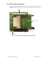
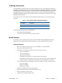
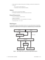
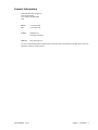
CM17109ER PC/104-Plus
Single- and Dual-Slot CardBus
utilityModules™
User’s Manual
BDM-610020052 Revision A
®
www.rtd.com
An ISO9001:2000 Company
“Accessing the Analog World”
®
CM17109ER PC/104-Plus Single- and Dual-Slot CardBus utilityModules™
User’s Manual
RTD Document Number: BDM-610020052 Revision A
Copyright © 2006 RTD Embedded Technologies, Inc. All rights reserved.
Trademarks
Advanced Digital I/O, aDIO, a2DIO, Autonomous SmartCal, dspFramework, dspModule, IDAN, HiDAN, HiDANplus,
“MIL Value for COTS prices”, multiPort, PC/104EZ, and utilityModule are trademarks, and “Accessing the Analog
World”, dataModule, RTD, and the RTD logo are registered trademarks of RTD Embedded Technologies, Inc. All other
trademarks appearing in this document are the property of their respective owners.
Contents and specifications within this manual are subject to change without notice.
Revision History
ii
Revision
Date
A
7/26/06
Reason for Change
Initial release.
CM17109ER CardBus utilityModule
BDM-610020052
Rev A
CM17109ER PC/104-Plus
Single- and Dual-Slot CardBus
utilityModules™
®
www.rtd.com
An ISO9001:2000 Company
“Accessing the Analog World”
®
iv
CM17109ER CardBus utilityModule
BDM-610020052
Rev A
Chapter 1
Introduction
CM17109ER CardBus utilityModule. . . . . . . . . . . . . . . . . . . . . . . . . . . . . . . . . . . . . . . . . . . . . . . . . . . . . . . . . .
2
Ordering Information . . . . . . . . . . . . . . . . . . . . . . . . . . . . . . . . . . . . . . . . . . . . . . . . . . . . . . . . . . . . . . . . . . . . . . . .
3
Board Features . . . . . . . . . . . . . . . . . . . . . . . . . . . . . . . . . . . . . . . . . . . . . . . . . . . . . . . . . . . . . . . . . . . . . . . . . . . . . . .
3
General Features . . . . . . . . . . . . . . . . . . . . . . . . . . . . . . . . . . . . . . . . . . . . . . . . . . . . . . . . . . . . . . . . . . . . . . . . . . . . . . . . . . .
Software . . . . . . . . . . . . . . . . . . . . . . . . . . . . . . . . . . . . . . . . . . . . . . . . . . . . . . . . . . . . . . . . . . . . . . . . . . . . . . . . . . . . . . . . . . .
Physical Characteristics . . . . . . . . . . . . . . . . . . . . . . . . . . . . . . . . . . . . . . . . . . . . . . . . . . . . . . . . . . . . . . . . . . . . . . . . . . . . .
Block Diagram . . . . . . . . . . . . . . . . . . . . . . . . . . . . . . . . . . . . . . . . . . . . . . . . . . . . . . . . . . . . . . . . . . . . . . . . . . . . . . . . . . . . .
3
4
4
4
Contact Information . . . . . . . . . . . . . . . . . . . . . . . . . . . . . . . . . . . . . . . . . . . . . . . . . . . . . . . . . . . . . . . . . . . . . . . . .
5
Chapter 2
Installing the CardBus utilityModule
CM17109ER Connectors . . . . . . . . . . . . . . . . . . . . . . . . . . . . . . . . . . . . . . . . . . . . . . . . . . . . . . . . . . . . . . . . . . . . .
8
PC Card Socket(s) Pinout (CN5). . . . . . . . . . . . . . . . . . . . . . . . . . . . . . . . . . . . . . . . . . . . . . . . . . . . . . . . . . . . . .
9
Switch SW1—PCI Slot Selector . . . . . . . . . . . . . . . . . . . . . . . . . . . . . . . . . . . . . . . . . . . . . . . . . . . . . . . . . . . . . . .
10
Bus Masters . . . . . . . . . . . . . . . . . . . . . . . . . . . . . . . . . . . . . . . . . . . . . . . . . . . . . . . . . . . . . . . . . . . . . . . . . . . . . . . . . . . . . . . .
10
Installation Considerations . . . . . . . . . . . . . . . . . . . . . . . . . . . . . . . . . . . . . . . . . . . . . . . . . . . . . . . . . . . . . . . . . .
11
Before You Begin . . . . . . . . . . . . . . . . . . . . . . . . . . . . . . . . . . . . . . . . . . . . . . . . . . . . . . . . . . . . . . . . . . . . . . . . . . . . .
11
Installing the CM17109ER in a PC/104-Plus Stack. . . . . . . . . . . . . . . . . . . . . . . . . . . . . . . . . . . . . . . . . . . .
12
Chapter 3
System Configuration
System Resource Allocation . . . . . . . . . . . . . . . . . . . . . . . . . . . . . . . . . . . . . . . . . . . . . . . . . . . . . . . . . . . . . . . . . .
14
IRQ Routing (ISA vs PCI) . . . . . . . . . . . . . . . . . . . . . . . . . . . . . . . . . . . . . . . . . . . . . . . . . . . . . . . . . . . . . . . . . . . . .
14
Programmable Interrupt Subsystem . . . . . . . . . . . . . . . . . . . . . . . . . . . . . . . . . . . . . . . . . . . . . . . . . . . . . . . . .
14
Appendix A Reference Information
LEDs and Solder Blobs . . . . . . . . . . . . . . . . . . . . . . . . . . . . . . . . . . . . . . . . . . . . . . . . . . . . . . . . . . . . . . . . . . . . . . . .
17
Physical Dimensions. . . . . . . . . . . . . . . . . . . . . . . . . . . . . . . . . . . . . . . . . . . . . . . . . . . . . . . . . . . . . . . . . . . . . . . . . .
19
PC Card Controller Information. . . . . . . . . . . . . . . . . . . . . . . . . . . . . . . . . . . . . . . . . . . . . . . . . . . . . . . . . . . . . .
20
Appendix B IDAN™ Dimensions
IDAN Dimensions and PC Card Slots . . . . . . . . . . . . . . . . . . . . . . . . . . . . . . . . . . . . . . . . . . . . . . . . . . . . . . . . .
22
IDAN-CM17109ER-1S . . . . . . . . . . . . . . . . . . . . . . . . . . . . . . . . . . . . . . . . . . . . . . . . . . . . . . . . . . . . . . . . . . . . . . . . . . . . . .
22
Appendix C Limited Warranty
BDM-610020052
Rev A
:
v
vi
CM17109ER CardBus utilityModule
BDM-610020052
Rev A
Chapter 1
Introduction
This manual provides comprehensive hardware and software information for users developing with the
CM17109ER PC/104-Plus CardBus utilityModule, which offers one or two PC Card slots on a single PC/104-Plus
board.
The term, PC Card, refers to the credit card-size peripherals that add memory, mass storage, and I/O capabilities
to systems in a rugged, compact form factor. The term, PCMCIA (Personal Computer Memory Card International
Association), refers to the association and standards body that promotes PC Card and ExpressCard technology.
In the past, PC Cards were known as PCMCIA Cards, but the industry now refers to products based on this
technology as PC Cards, PC Card Hosts, and PC Card Software, whereas PCMCIA refers only to the association.
Note Throughout this manual, the term, PC Card, is used generically for the peripherals or the slot(s) for
such peripherals, while the term, CardBus, is used to refer to the 32-bit PC Card interface.
The flexibility of the CM17109ER meets the needs of a variety of applications through support of Type I, Type II,
and Type III PC Cards. Type I PC Cards are typically used for memory devices such as RAM, Flash, and SRAM
cards. Type II PC Cards are typically used for I/O devices such as data/fax modems, Ethernet, and mass storage
devices. Type III PC Cards are used for devices with thicker components, such as rotating mass storage devices.
All three card types measure the same length and width and use the same 68-pin connector. Because they differ
only in thickness and not electrical/software interface, a thinner card can be used in a thicker slot, but a thicker
card cannot be used in a thinner slot. Only the mechanical size of the larger card prevents it from fitting into the
smaller slot. Extended cards allow the addition of components that must remain outside the system for proper
operation, such as antennas for wireless applications.
This manual is organized as follows:
Chapter 1
Introduction
introduces main features and specifications
Chapter 2
Installing the CardBus utilityModule
describes the connectors, external I/O connections, and installation of the CM17109ER
Chapter 3
System Configuration
addresses system configuration resources regarding the CardBus controller, inserted PC
Cards, IRQ routing, and the programmable interrupt subsystem
Appendix A
Reference Information
provides operating system considerations and physical dimensions of the CM17109ER
Appendix B
IDAN™ Dimensions
provides connector pinouts for the CM17109ER installed in an RTD Intelligent Data
Acquisition Node (IDAN) frame
Appendix C
Limited Warranty
BDM-610020052
Rev A
Chapter 1: Introduction
1
CM17109ER CardBus utilityModule
The CM17109ER CardBus utilityModule features support for Type I, Type II, and Type III PC Cards. The dual-slot
CM17109ER-2 CardBus utilityModule is shown below. A single-slot CM17109ER-1 CardBus utilityModule is also
available.
PCI Bus
PC Card Slot(s)
PC/104 Bus (XT)
PC/104 Bus (AT)
PCI Slot Selector Switch
Figure 1
2
CM17109ER CardBus utilityModule (top view, CM17109ER-2)
CM17109ER CardBus utilityModule
BDM-610020052
Rev A
Ordering Information
The CM17109ER is a peripheral module that can also be purchased as part of an Intelligent Data Acquisition
Node (IDAN™) building block, which consists of the CM17109ER and a milled aluminum IDAN frame. The IDAN
building block can be used in just about any combination with other IDAN building blocks to create a simple
but rugged PC/104 stack. The CM17109ER can also be purchased as part of a custom-built RTD HiDAN™ or
HiDANplus High Reliability Intelligent Data Acquisition Node. Contact RTD for more information on our high
reliability PC/PCI-104 systems.
The model options are shown below. Refer to the RTD website (www.rtd.com) for more detailed ordering
information.
Table 1 CM17109ER CardBus utilityModule Options
Part Number
Description
CM17109ER-1
utilityModule with one PC Card slot
CM17109ER-2
utilityModule with two PC Card slots
Each CM17109ER package contains the following items:
•
•
CM17109ER CardBus utilityModule
Companion CD containing software and documentation
Board Features
The following sections describe the major features of the CM17109ER CardBus utilityModule, which was
designed to provide CardBus support for RTD cpuModules™ or other standard PC/104-Plus modules.
General Features
•
•
•
•
•
•
•
•
BDM-610020052
One or two CardBus slots with ejectors (1 slot: CM17109ER-1; 2 slots: CM17109ER-2)
Supports PC Card Standard 7.1 Release
Supports Type I, II, and III PC Card types (54.0 x 85.6 mm; 68-pin connector)
–
Type I: 3.3 mm thickness
–
Type II: 5.0 mm thickness
–
Type III: 10.5 mm thickness
–
CM17109ER-1: Accepts Type I, II, or III PC Card types in the single slot
–
CM17109ER-2: Simultaneously accepts Type I, II, or III PC Cards in the top slot (considered the
first slot) and a Type I or Type II PC Card in the bottom slot (considered the second slot)
32-bit CardBus interface (actual throughput may be substantially less than theoretical maximums)
–
Byte mode: 33 MB/s
–
Word mode: 66 MB/s
–
DWord mode: 132 MB/s
Backwards-compatible with older PC Card standards
Permits insertion and removal of cards with system power on
LED(s) to indicate PC Card slot activity
Supports both 5 VDC and 3.3 VDC PC Cards
Rev A
Chapter 1: Introduction
3
•
•
Power requirements: 0.25W @ 5 VDC typical (not including current draw from CardBus Devices)
Connectors:
–
One or two PC Card slots with ejectors
–
PC/104-Plus form factor (AT/XT bus and ISA bus)
Software
•
•
Natively supported under Windows 2000/XP
Linux support is included in recent 2.4 and 2.6 kernels (Yenta driver)
Physical Characteristics
•
•
•
•
Size: 3.8 x 5.1 x 0.6 inches (96 x 129 x 15 mm)
Weight: 0.14 lbs (0.06 kg)
Operating Temperature: 0 to +70ºC, 90% humidy, non-c ondensing
Storage Temperature: –55 to +125 °C
Block Diagram
The CM17109ER is designed on the PC/104-Plus form factor for an easy mechanical interface to PC/104-Plus
systems. Refer to PC Card Socket(s) Pinout (CN5) on page 9 for a detailed discussion of the CM17109ER CardBus
utilityModule external I/O connections. The next figure shows a simplified block diagram of the CM17109ER.
ISA Bus
PCI Bus
Interrupts
Interrupts
TI PCI950 Deserializer
PCI bus signals
Interrupts
TI PCI1520
Control Signals
Power Switch
Socket 1
Socket 2
Figure 2 CM17109ER CardBus utilityModule Simplified Block Diagram
4
CM17109ER CardBus utilityModule
BDM-610020052
Rev A
Contact Information
RTD Embedded Technologies, Inc.
103 Innovation Blvd.
State College, PA 16803-0906
USA
Phone:
Fax:
+1-814-234-8087
+1-814-234-5218
E-mail:
[email protected]
[email protected]
Internet:
http://www.rtd.com
Be sure to check the RTD web site (www.rtd.com) frequently for product updates, including newer versions of
application software and this manual.
BDM-610020052
Rev A
Chapter 1: Introduction
5
6
CM17109ER CardBus utilityModule
BDM-610020052
Rev A
Chapter 2
Installing the CardBus utilityModule
The CM17109ER utilityModule interfaces easily to PC/104-Plus systems. This chapter shows the external I/O
connections and connector pinouts, and provides module installation instructions.
BDM-610020052
Rev A
Chapter 2: Installing the CardBus utilityModule
7
CM17109ER Connectors
Figure 3 shows the connectors and PCI Slot Selector Switch of the CM17109ER CardBus utilityModule.
CN4
CN5
CN1
SW1
CN2
Figure 3
CN3
CM17109ER Connectors
Note Pin 1 of each connector is indicated by a square within a white square on both the top and bottom
of the board. Pin 1 of the XT and AT connectors match when stacking with other PC/104 modules.
Table 2 CM17109ER Connectors
Connector
8
Function
Size
CN1
PC/104 Bus (XT)
64-pin
CN2
PC/104 Bus (AT)
40-pin
CN3
Reserved
4-pin
CN4
PCI Bus
120-pin
CN5
PC Card Socket(s)
170-pin
SW1
PCI Slot Selector Switch
—
CM17109ER CardBus utilityModule
BDM-610020052
Rev A
PC Card Socket(s) Pinout (CN5)
The following table describes the PC Card (32-bit CardBus) pinout of the single CM17109ER PC Card socket
(CM17109ER-1) or each of the two CM17109ER PC Card sockets (CM17109ER-2).
Table 3
BDM-610020052
Pin #
Signal Name
1
GND
2
CM17109ER Connector Pinout
Pin Function
Pin #
Signal Name
Pin Function
Ground
35
GND
Ground
CAD0
Address/data bit 0 (I/O)
36
CCD1
Card Detect 1
3
CAD1
Address/data bit 1 (I/O)
37
CAD2
Address/data bit 2 (I/O)
4
CAD3
Address/data bit 3 (I/O)
38
CAD4
Address/data bit 4 (I/O)
5
CAD5
Address/data bit 5 (I/O)
39
CAD6
Address/data bit 6 (I/O)
6
CAD7
Address/data bit 7 (I/O)
40
RFU
Reserved for future use
7
CC/BE0
Byte Enable (input)
41
CAD8
Address/data bit 8 (I/O)
Address/data bit 10 (I/O)
8
CAD9
Address/data bit 9 (input)
42
CAD10
9
CAD11
Address/data bit 11 (I/O)
43
CVS1
10
CAD12
Address/data bit 12 ( input)
44
CAD13
Address/data bit 13 (I/O)
11
CAD14
Address/data bit 14 (input)
45
CAD15
Address/data bit 15 (I/O)
12
CC/BE1
Byte Enable 1 (input)
46
CAD16
13
CPAR
Parity Bit (input)
47
RFU
14
PERR
Parity Error (input)
48
CBCLOCK
—
15
CGNT
Bus arbitration grant (input)
49
CSTOP
—
16
CINT
17
Vcc
18
19
Input
Address/data bit 16 (I/O)
Reserved for future use
Ready/Bus (output)
50
CDEVSEL
Supply Voltage
51
Vcc
Device Select
Vpp1
Programming Voltage 1
52
Vpp2
CCLK
Bus clock, 0 to 33MHz
53
CTRDY
20
CIRDY
Ready (input)
54
CFRAME
21
CC/BE2
Byte enable 2 (input)
55
CAD17
Address/data bit 17 (I/O)
22
CAD18
Address/data bit 18 (I/O)
56
CAD19
Address/data bit 19 (I/O)
23
CAD20
Address/data bit 20 (I/O)
57
CVS2
24
CAD21
Address/data bit 21 (I/O)
58
CRST
Reset
25
CAD22
Address/data bit 22 (I/O)
59
CSERR
System Reset
26
CAD23
Address/data bit 23 (I/O)
60
CREQ
Arbitration Request
27
CAD24
Address/data bit 24 (I/O)
61
CC/BE3
Supply Voltage
Programming Voltage 2
—
Data Frame Indicator
—
Byte Enable 3
28
CAD25
Address/data bit 25 (I/O)
62
CAUDIO
Card Audio (output)
29
CAD26
Address/data bit 26 (I/O)
63
CSTSCHG
—
30
CAD27
Address/data bit 27 (I/O)
64
CAD28
Address/data bit 28 (I/O)
31
CAD29
Address/data bit 29 (I/O)
65
CAD30
Address/data bit 30 (I/O)
32
RFU
Reserved for future use
66
CAD31
Address/data bit 31 (I/O)
33
CCLKRUN
Output
67
CCD2
Card Detect 2
34
GND
Ground
68
GND
Ground
Rev A
Chapter 2: Installing the CardBus utilityModule
9
Switch SW1—PCI Slot Selector
This rotary switch is used to set the positioning of the CM17109ER with respect to the CPU module and other
PC/104-Plus or PCI-104 cards in the stack.
Note All PC/104-Plus modules (including the CM17109ER) and PCI-104 modules must be on the same
side of the CPU module.
Bus Masters
Notice the Bus Master column in Table 4 below. The CM17109ER can be a bus master, meaning that it can take
control of the bus. RTD’s newer cpuModules—including Intel® Pentium® M, Celeron® M, and Celeron®, and VIA
Eden™ and AMD Geode™ HX series cpuModules—support 4 PCI bus masters (for all four PCI slots), but some
older CPUs only support 3 bus masters (in which only PCI slots 0, 1, and 2 may be bus masters). However, older
CPUs that only support 3 bus masters can still use four devices in PCI slots, but only 3 of the 4 slots may be bus
masters.
If your CPU supports 4 bus masters, you will want to set the PCI Slot Selector Switch to position 0, 1, 2, or 3
(corresponding to PCI bus master 0, 1, 2, or 3). If the CM17109ER is the first module from the CPU module, set
the switch to position "0". If it is the second module from the CPU module, set the switch to position "1". Similarly,
position "2" refers to the third module and position "3" refers to the fourth module away from the CPU module.
If your CPU only supports 3 bus masters, you will want to set the switch to position 4, 5, 6, or 7 (corresponding
to PCI bus master 0, 1, 2, or 2). This might seem like PCI slots 6 and 7 appear to be the same, but they are not.
These two options are different; they allow you to use the CM17109ER as a bus master in either PCI slot 2 or 3 if
your CPU only supports 3 bus masters. If the CM17109ER is the first module from the CPU module, which only
supports 3 bus masters, set the switch to position "4". If it is the second module from the CPU module, set the
switch to position "5". Similarly, position "6" refers to the third module and position "7" refers to the fourth
module away from the CPU module.
Table 4
10
PCI Slot Selector Switch
Switch Position
PCI Slot Number
Bus Master
0
Slot 0 (closest to CPU)
0
1
Slot 1
1
2
Slot 2
2
3
Slot 3
3
4
Slot 0 (closest to CPU)
0
5
Slot 1
1
6
Slot 2
2
7
Slot 3
2
CM17109ER CardBus utilityModule
BDM-610020052
Rev A
Installation Considerations
Consider the following points before integrating the CM17109ER into a PC/104-Plus stack.
1.
The CM17109ER is a PC/104-Plus module with an ISA bus (PC XT and AT connectors) and a PCI bus.
Therefore, the CM17109ER should be installed with a PC/104-Plus or PCI-104 cpuModule and other
PC/104-Plus or PCI-104 peripheral modules.
2.
RTD recommends building your PC/104-Plus or PCI-104 computer by stacking the power supply
module and cpuModule on the ends of the stack. These two modules produce heat, and stacking them
on the top and bottom maximizes heat dissipation. Placing the cpuModule on one end of the stack also
minimizes reflections. RTD-built PC/104-Plus systems, such as the Intelligent Data Acquisition Node
(IDAN™), normally have a power supply module on the bottom and a cpuModule on the top. Any other
combination of PC/104-Plus or PCI-104 modules, including the CM17109ER, can be integrated into the
stack.
Before You Begin
CAUTION Keep your CM17109ER in the antistatic bag until you are ready to install it to your system!
When removing the CM17109ER from the antistatic bag, hold it at the edges and do not touch the components
or connectors. Please handle the module in an antistatic environment and use a grounded workbench for testing
and handling.
BDM-610020052
Rev A
Chapter 2: Installing the CardBus utilityModule
11
Installing the CM17109ER in a PC/104-Plus Stack
CAUTION The CM17109ER should slide into the matching PC/104 connector easily. Do not force the
connection. Doing so might bend or break pins.
Note All PC/104-Plus and PCI-104 modules (including the CM17109ER) must be on the same side of the
CPU module.
1.
Turn off power to your PC/104-Plus or PCI-104 system and unplug the cord.
2.
Ground yourself with an anti-static strap.
3.
Check that the keying pins in the PC/104 bus connector are properly positioned. Two keying pins
should reside in pins C19 and B10.
4.
Use the PCI slot selector switch SW1 to set the positioning of the CM17109ER with respect to the CPU
module and other PC/104-Plus or PCI-104 cards in the stack. (Refer to Switch SW1—PCI Slot Selector on
page 10.)
5.
Line up the pins of the CM17109ER’s PC/104 connector with the PC/104 bus of the stack and gently
press the module onto the stack. The module should slide into the matching PC/104-Plus and PCI
connectors easily. Do not attempt to force the module, as this can lead to bent/broken pins.
Note If the CM17109ER does not press into place, check modules in your stack for bent pins or
out-of-place keying pins, and try again.
12
6.
If any modules are to be installed above the CM17109ER, install them. If the other modules are
PC/104-Plus or PCI-104 devices, set the PCI slot selector switches on these modules based on their
position away from the CPU module.
7.
Attach any necessary cables to the PC/104-Plus stack.
8.
Reconnect the power cord and apply power to the stack.
9.
Boot the system and verify that all of the hardware is working properly.
CM17109ER CardBus utilityModule
BDM-610020052
Rev A
Chapter 3
System Configuration
This chapter addresses the resources that must be assigned to the CardBus controller, the resources that must
be assigned to any inserted PC Cards, IRQ routing, and the programmable interrupt subsystem.
BDM-610020052
Rev A
Chapter 3: System Configuration
13
System Resource Allocation
The CM17109ER requires multiple sets of system resources (I/O ports, memory address, IRQs, DMA channels)
assigned to it.
First, resources must be assigned to the CardBus controller. Since the controller is a PCI device, its resources are
assigned dynamically by the BIOS or operating system at boot time. Second, resources must be assigned to any
inserted PC Cards. This assignment occurs dynamically when a PC Card is inserted. The specific resources that
are used will depend on the type of card. For example, an ATA Flash card will require different resources than a
Wireless LAN card. Resources are assigned to each card if two cards are inserted in the CM17109ER-2
utilityModule. The method for assigning these resources is controlled by the operating system and its PC Card
drivers. For more information on how the resources are assigned, consult your operating system documentation.
IRQ Routing (ISA vs PCI)
The CM17109ER can route PC Card interrupts over either the PCI or ISA bus. How the interrupts are routed will
depend on the following factors:
•
The throughput of the PC Card interface (older 16-bit vs 32-bit CardBus). Older 16-bit PC Cards
traditionally have their IRQs routed to the ISA bus, while CardBus cards have their IRQs routed to the
PCI bus.
•
The software configuration of the PCI1520 controller, which is determined by the operating system and
its PC Card drivers. The operating system may remap IRQs for older 16-bit PC Cards onto the PCI bus.
IRQ routing may differ depending on the operating system version and configuration. Some known issues:
•
Newer versions of Windows use PCI interrupts more aggressively than older versions. For example,
Windows XP (with ACPI HAL) will map older 16-bit PC Card IRQs to the PCI bus, while Windows 2000
will map them to the ISA bus.
•
Under Windows, when the ACPI HAL is loaded, PCI interrupts are used more aggressively. The CardBus
controller may require ISA interrupts in non-ACPI mode, but will not require them in ACPI mode.
Note If your PC Card's IRQs are mapped to the ISA bus, you may have difficulty using it on a CPU
without an ISA bus (e.g., a PCI-104 cpuModule). If you have a CPU without an ISA bus, it is strongly
recommended that you use an operating system that maps all PC Card IRQs onto the PCI bus (e.g.,
Windows XP with ACPI HAL).
Note If using legacy PC Card devices in Windows, you may need to reserve the device’s IRQ for legacy
devices in the system’s BIOS. The device IRQ can be found by looking in the device manager in Windows.
Programmable Interrupt Subsystem
Interrupts provide a way for I/O devices to let the microprocessor know that a device requires servicing. The
dynamic nature of PC Cards and the many PC Card I/O applications require substantial interrupt support from
the PC Card controller PCI1520 chip. The PCI1520 provides several interrupt signaling schemes to accommodate
the needs of a variety of platforms. The different mechanisms for dealing with interrupts in this device are based
on various specifications and industry standards.
The ExCA register set provides interrupt control for some 16-bit PC Card functions, and the CardBus socket
register set provides interrupt control for the CardBus PC Card functions. The PCI1520 is, therefore, backward
compatible with existing interrupt control register definitions, and new registers have been defined where
required.
The PCI1520 detects PC Card interrupts and events at the PC Card interface and notifies the host controller using
one of several interrupt signaling protocols. PC Card interrupts are classified as either card status change (CSC)
or as functional interrupts. The method by which any type of PCI1520 interrupt is communicated to the host
14
CM17109ER CardBus utilityModule
BDM-610020052
Rev A
interrupt controller varies from system to system. The PCI1520 offers system designers the choice of using
parallel PCI interrupt signaling, parallel ISA-type IRQ interrupt signaling, or the IRQSER serialized ISA and/or PCI
interrupt protocol. It is possible to use the parallel PCI interrupts in combination with either parallel IRQs or
serialized IRQs, Refer to PCI1510 Implementation Guide found at http://www.ti.com for more information.
BDM-610020052
Rev A
Chapter 3: System Configuration
15
16
CM17109ER CardBus utilityModule
BDM-610020052
Rev A
Appendix A
Reference Information
This appendix provides reference information for the CM17109ER PC Card utilityModule.
LEDs and Solder Blobs
Table 5 describes the LEDs shown below.
D1
D2
Figure 4 CM17109ER LEDs (top view)
Table 5
CM17109ER LEDs
LED
Function
D1
On: Slot 1 activity
Off: no activity
D21
On: Slot 2 activity
Off: no activity
1. Used on CM17109ER-2 only.
BDM-610020052
Rev A
Appendix A: Reference Information
17
Table 6 describes the solder blobs shown below.
B2
B1
Figure 5 CM17109ER Solder Blobs (bottom view)
Table 6
18
CM17109ER Solder Blobs
Solder Blob
Positions
B1
B2
CM17109ER CardBus utilityModule
Function
Default
2
Factory use only
open
2
Factory use only
open
BDM-610020052
Rev A
Physical Dimensions
0.300 in
0.200 in
0.330 in
0.288 in
3.775 in
0.350 in
0.210 in
Figure 6 shows the mechanical dimensions of the CM17109ER PC Card utilityModule (in inches).
3.550 in
4.200 in
Figure 6 CM17109ER Physical Dimensions (±0.005 inches)
BDM-610020052
Rev A
Appendix A: Reference Information
19
PC Card Controller Information
Refer to the Texas Instruments website for detailed information on the PC Card controller PCI1520 chip
(http://focus.ti.com/docs/prod/folders/print/pci1520.html) and on the PCI950 serial interrupt stream
deserializer (http://focus.ti.com/docs/prod/folders/print/pci950.html).
Refer to http://www.pcmcia.org/pccard.htm for a primer on PC Card Standard.
Refer to http://www.pcmcia.org/faq.htm for a list of frequently asked questions on the PC Card Standard, how it
compares to the new ExpressCard standard, the different types of PC Cards, CardBus, and more.
20
CM17109ER CardBus utilityModule
BDM-610020052
Rev A
Appendix B
IDAN™ Dimensions
RTD’s PC Card utilityModules, like all other RTD PC/PCI-104 modules, can be packaged in Intelligent Data
Acquisition Node (IDAN) frames, which are milled aluminum frames with integrated heat sinks and heat pipes
for fanless operation. RTD modules installed in IDAN frames are called building blocks. IDAN building blocks
maintain the simple but rugged PC/104 stacking concept. Each RTD module is mounted in its own IDAN frame
and all I/O connections are brought to the walls of each frame using standard PC connectors. No connections
are made from module to module internal to the system other than through the PC/104 and PC/104-Plus bus,
enabling quick interchangeability and system expansion without hours of rewiring and board redesign.
The CM17109ER PC Card utilityModule can also be purchased as part of a custom-built RTD HiDAN™ or
HiDANplus™ High Reliability Intelligent Data Acquisition Node. This appendix provides the dimensions and
pinouts of the CM17109ER installed in an IDAN frame. Contact RTD for more information on high reliability
IDAN, HiDAN, and HiDANplus PC/PCI-104 systems.
IDAN—Adhering to the PC/104 stacking concept,
IDAN allows you to build a customized system
with any combination of RTD modules.
IDAN Heat Pipes—Advanced heat pipe technology
maximizes heat transfer to heat sink fins.
HiDANplus—Integrating the modularity of
IDAN with the ruggedization of HiDAN,
HiDANplus enables connectors on all system
frames, with signals running between frames
through a dedicated stack-through raceway.
BDM-610020052
Rev A
Appendix B: IDAN™ Dimensions
21
IDAN Dimensions and PC Card Slots
IDAN-CM17109ER-1S
Figure 7 IDAN-CM17109ER-1S Dimensions (Front)
Figure 8
IDAN-CM17109ER-1S Cover Plate
Note Drawings are not to scale.
22
CM17109ER CardBus utilityModule
BDM-610020052
Rev A
Figure 9
IDAN-CM17109HR-1S PC Card Slots
Note Photographs are not to scale.
BDM-610020052
Rev A
Appendix B: IDAN™ Dimensions
23
24
CM17109ER CardBus utilityModule
BDM-610020052
Rev A
Appendix C
Limited Warranty
RTD Embedded Technologies, Inc. warrants the hardware and software products it manufactures and produces
to be free from defects in materials and workmanship for one year following the date of shipment from RTD
Embedded Technologies, Inc. This warranty is limited to the original purchaser of product and is not transferable.
During the one year warranty period, RTD Embedded Technologies will repair or replace, at its option, any
defective products or parts at no additional charge, provided that the product is returned, shipping prepaid, to
RTD Embedded Technologies. All replaced parts and products become the property of RTD Embedded
Technologies. Before returning any product for repair, customers are required to contact the factory for a Return
Material Authorization number.
This limited warranty does not extend to any products which have been damaged as a result of accident, misuse,
abuse (such as: use of incorrect input voltages, improper or insufficient ventilation, failure to follow the
operating instructions that are provided by RTD Embedded Technologies, "acts of god" or other contingencies
beyond the control of RTD Embedded Technologies), or as a result of service or modification by anyone other
than RTD Embedded Technologies. Except as expressly set forth above, no other warranties are expressed or
implied, including, but not limited to, any implied warranties of merchantability and fitness for a particular
purpose, and RTD Embedded Technologies expressly disclaims all warranties not stated herein. All implied
warranties, including implied warranties for merchantability and fitness for a particular purpose, are limited to
the duration of this warranty. In the event the product is not free from defects as warranted above, the
purchaser's sole remedy shall be repair or replacement as provided above. Under no circumstances will RTD
Embedded Technologies be liable to the purchaser or any user for any damages, including any incidental or
consequential damages, expenses, lost profits, lost savings, or other damages arising out of the use or inability to
use the product.
Some states do not allow the exclusion or limitation of incidental or consequential damages for consumer
products, and some states do not allow limitations on how long an implied warranty lasts, so the above
limitations or exclusions may not apply to you.
This warranty gives you specific legal rights, and you may also have other rights which vary from state to state.
RTD Embedded Technologies, Inc.
103 Innovation Blvd.
State College PA 16803-0906
USA
Website: www.rtd.com
BDM-610020052
Rev A
Appendix C: Limited Warranty
25
26
CM17109ER CardBus utilityModule
BDM-610020052
Rev A