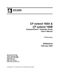
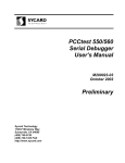
1
PCChost 1420 PCI-CardBus Host Adapter User’s Manual Preliminary M200157-00 January 2005 Sycard Technology 1180-F Miraloma Way Sunnyvale, CA 94085 (408) 749-0130 (408) 749-1323 FAX http://www.sycard.com PCChost 1420 User’s Manual Page 1 1.0 Introduction The PCChost 1420 host adapter is a PCI plug-in board designed evaluate the Texas Instruments PCI1420 PCI-CardBus bridge device. The PCI1420 is the 4th generation of TI's CardBus controllers and offers high performance and low power. The PCChost 1420 has the following features: • • • • • • • • • • • • Based on the high performance PCI1420 PCI to CardBus bridge ACPI compliant Dual sockets support both 16 bit and CardBus cards Support for both ISA and PCI interrupts LEDs indicate slot power and activity Supports Zoomed Video on both slots Overcurrent LED informs user of error condition TPS2206 Vpp and Vcc switch supports all Vpp and Vcc options On-board 12V Vpp supply eliminates problems caused by poorly regulated host power Adjustable 3.3V Power supply for voltage margin testing On-board speaker All PCI1420 signals accessible through test points for easy logic analyzer connection. 1.1 Packing List The PCChost 1420 package includes the following: • • • • • • PCChost 1420 PC Board PCChost 1010 ISA Interrupt Board 10 pin ribbon cable PCI1420 Data Sheet PCChost 1420 User’s Manual Registration Card 1.2 Specifications Electrical Supply Voltage: 5V +-5% Supply Current: TBD Physical Width: Length: Thickness: Weight: 5.0” 8.75” 0.8” Max 5.5 oz 1.3 Related Documentation Sycard Technology's PCMCIA Developer’s Guide - Third Edition Texas Instruments PCI1420 Data Sheet TPS2206 Data Sheet The PC Card Specification - Release 7.0 M200157-00 1994-2005 Sycard Technology Page 2 PCChost 1420 User’s Manual 1.4 Technical Support Technical support for the PCChost 1420 can be obtained directly from Sycard Technology. You may reach Sycard via phone or FAX at the following: (408) 749-0130 (408) 749-1323 FAX Commonly asked questions and answers can be found on Sycard's web site at the following URL: http://www.sycard.com/h1420_qa.html You may also direct questions, comments, suggestions or any other issues to the following email address: [email protected] 1994-2005 Sycard Technology M200157-00 PCChost 1420 User’s Manual Page 3 2.0 PCChost 1420 Installation The PCChost 1420 is designed to work in most Windows 98/ME/2000/XP based systems. The PCChost 1420 package contains the PCChost 1420 PCI-CardBus interface and associated documentation. 2.1 Configuring the Hardware As shipped from the factory the PCChost 1420 is ready to be installed in a standard PC Architecture machine. The following jumpers are configured at the factory: Jumper Setting Description JP6 1-2 shorted Adjustable 3.3V Vcc JP7 1-2 shorted ZV Buffer Enable 0 JP7 3-4 open JP7 5-6 shorted Slot 1 Activity LED JP7 7-8 shorted IRQSER Signal JP7 9-10 open JP7 11-12 shorted Slot 0 Activity LED JP7 13-16 shorted External EEPROM JP7 15-14 shorted External EEPROM Table 2.1-1 Factory Jumper Settings Other jumpers and test points integrated on the board are used to access advanced features. These features are listed in section 3.0 and 4.0. 2.2 Installing the Hardware The PCChost 1420 can be installed in any available PCI slot. Insure that the bracket is properly fastened to the chassis with a screw or other device. This will prevent the PCChost 1420 from being pulled from the slot when a PC Card is inserted. 2.3 Installing the Software Driver The on-board EEPROM on the PCChost 1420 will initialize the board for Window 98/ME/2000 and XP. These versions of windows have built-in support for the PCI-1420 chip used on the PCCHost 1420. No other software drivers are required. M200157-00 1994-2005 Sycard Technology 1994-2005 Sycard Technology SLOT 0 D2 D7 D6 Pwr ZV Act 1 P1 JP10 1 ICs U10-U15 JP9 PCI 1420 1 1 1 1 D4 JP11 JP1 OverCur JP8 1 U9 JP7 P2 SLOT 1 U2 1 Speaker U3 JP6 TP1 R46 D3 D8 D5 Pwr ZV Act Page 4 PCChost 1420 User’s Manual M200157-00 PCChost 1420 User’s Manual Page 5 3.0 Using the PCChost 1420 In most applications the PCChost 1420 requires no adjustments or jumper changes. The following sections describe the operation of some of the less frequently used features. 3.1 Adjusting the 3.3V Vcc A single 3.3V on-board power supply provides power for both PC Card slots. Via jumper JP6, the power supply can be configured for fixed or adjustable operation. In the fixed position (JP6 pins 2-3 shorted), the power supply supplies a fixed 3.3V output. When JP6 pins 1-2 are shorted the 3.3V power supply is adjustable from approximately 3.0 to 3.6 volts to allow for voltage margin testing of a PC Card. JP6 Position Description 1-2 Adjustable 3.3V 2-3 Fixed 3.3V Table 3.1-1 Fixed/Adjustable Vcc Select Caution: Do not change the position of JP6 when power is applied to the PCChost unit. Damage to the PCChost and the host system may occur. The trimpot (R46) adjusts the voltage. To adjust the power supply, connect a voltmeter between the 3.3V test point at TP1 and ground. Remove any installed PC Cards from the slot. Apply power to the board and adjust the trimpot until the desired voltage is obtained. Note: The trimpot only adjusts the 3.3V power to the PC Card slots. Another fixed 3.3V regulator powers the PCI1420 core functions. Note: 5V power to the PC Card slots is derived directly from the PCI Vcc rails. No adjustments to the 5V slot voltage is possible. 3.2 Zoomed Video connection Zoomed Video PC Cards output digital video signals compatible with ZV ports of many video controllers. The Zoomed Video signals are shared with the 16-bit PC Card signals. Buffers on the PCChost 1420 board isolate the card slots from the ZV connectors at JP9 and JP10. The buffers allow the ZV signals from either slot to be routed to the JP9 and JP10. JP9 is a 40 pin connector that contains the ZV digital video signals. JP10 contains the I2S stereo audio signal. Pinouts of these connectors can be found on the schematics in Appendix C. M200157-00 1994-2005 Sycard Technology Page 6 PCChost 1420 User’s Manual 4.0 Hardware Description This section will describe the major operational blocks that make up the PCChost 1420. Additional details can be found in the TI PCI1420 datasheet included in the documentation package. 4.1 PCI-1420 PCI to CardBus Bridge The heart of the PCChost 1420 is Texas Instruments PCI1420 PCI to CardBus bridge. The PCI1420 chips directly connect to the PCI bus and PC Card slots to provides a true-single chip CardBus host implementation. A full detailed description of the PCI1420 can be found in the accompanying PCI1420 data sheet. The PCChost 1420 provides 0.1” spaced headers for accessing all PCI1420 signal pins. These pins can be probed by an oscilloscope or connected directly to a logic analyzer for system debug. A pin map for this header is shown in appendix A. 4.2 Power Supply and Power Distribution The PCChost 1420 contains eight separate power planes. They are as follows: • • • • • • • • 5 Volt PCI power supply 3.3 Volt PCI1420 “core” power supply Adjustable 3.3 Volt card power supply 12 Volt programming voltage power supply (Vpp) Slot A Vcc supply Slot B Vcc supply Slot A Vpp supply Slot B Vpp supply The following diagram illustrates the connection of the various power planes. 1994-2005 Sycard Technology M200157-00 PCChost 1420 User’s Manual Page 7 TPS2206 Vcc/Vpp Switch 5V Vcc PCI Bus LT1086 3.3V Slot LT1109-12 12V Vpp Slot A Vcc SLOT A Slot A Vpp Slot B Vcc SLOT B Slot B Vpp LT1121CZ DAT 3.3V Core CLK LAT Vcc VccA VccB PCI1420 CardBus Socket Controller Figure 4.2-1 PCChost 1420 power distribution 4.2.1 3.3 Volt PC Card Slot Power Supply The 3.3V card slot power supply is responsible for supplying power to both PC Card slots. The 3.3V power supply is based on a Linear Technology LT1086 low dropout adjustable regulator. Input to the LT1086 is the PCI 5V supply. The output voltage is determined by a resistor divider across the output pins of the device. The PCChost 1420 includes a jumper (JP6) to select a fixed 3.3V output or an adjustable 3.3V supply capable of supplying 3.0V to 3.6V. 3.3V PC Card slot power is connected to the TPS2206 Vcc/Vpp switch. 4.2.2 3.3 Volt PCI1420 “Core” Power Supply The 3.3V PCI1420 “core” power supply provides power for the core portion of the PCI1420. The core power supply is separately regulated by a LT1121CZ-3.3 fixed 3.3V regulator. The input to the LT1121CZ is the PCI 5V supply. The output connects directly to the PCI1420 core Vcc pins. 4.2.3 12 Volt Power Supply A Linear Technology LT1109-12 Vpp generator chip and associated circuitry provide 12 volt power for the Vpp1 and Vpp2 pins on each PC card slot. The input to the LT1109-12 is from the host system 5.0V Vcc. The output connects directly to the TPS2206 Vcc/Vpp switch. 4.2.4 Vcc/Vpp switch Slot Vcc and Vpp are controlled by the PCI1420 via a external power switch chip. The PCChost 1420 takes advantage of a single chip power switching chip specifically designed for the PC Card environment, the Texas Instruments TPS2206. The TPS2206 supports Vcc and Vpp switching for two PC Card slots and provides over-current protection. The control interface to the TPS2206 is via a three wire serial connection to the PCI1420. M200157-00 1994-2005 Sycard Technology Page 8 PCChost 1420 User’s Manual 4.2.5 LED Indicators Three power indicators display the current slot power status and any overcurrent situation on either slot. Green LEDs adjacent to each slot indicate the present slot power status. A single red LED at D4 labeled "OVC" indicates an overcurrent situation on either socket A RED LED indicates socket activity and a YELLOW led indicates Zoomed Video status. 4.3 Interrupt Deserializer Because of pin limitations on the PCI1420, interrupts are converted to a serial bitstream and converted to parallel interrupt in an external chip. This chip, the PCI950, is located at U9. Figure 4.3-1 illustrates the connections between the PCI1420 and the PCI950. The PCI950 converts the serial bitstream into the ISA and PCI style interrupts. PCLK INTA# INTB# INTC# INTD# PCLK TI PCI950 IRQSER IRQ3 IRQ4 IRQ5 IRQ7 IRQ9 IRQ10 IRQ11 IRQ12 IRQ14 IRQ15 TI PC I-1420 C ardB us C ontroller Slot 0 Slot 1 Figure 4.3-1 PCI950 Interrupt Deserializer The PCI interrupts are routed directly to the corresponding pins on the PCI connector. Since ISA interrupts are not available on the PCI connector, these must be routed through a 10-pin ribbon cable to a plug-in ISA interrupt board. See Figure 4.3-2. Since most new motherboards do not support ISA slots all later Microsoft operating systems configure the CardBus controller to route 16-bit ISA interrupts to the PCI interrupt mechanism. 1994-2005 Sycard Technology M200157-00 PCChost 1420 User’s Manual Page 9 PCChost 1420 INTAINTBINTCINTD- To PCI Bus ISA Interrupts IRQ3 IRQ4 IRQ5 IRQ7 IRQ9 IRQ10 IRQ11 IRQ12 IRQ14 IRQ15 PCI950 IRQ3 IRQ4 IRQ5 IRQ7 IRQ9 IRQ10 IRQ11 IRQ12 IRQ14 IRQ15 ISA Interrupt Board Figure 4.3-2 ISA Interrupt Routing 4.4 Zoomed Video Buffers In order to isolate the PC Card slot from potentially long traces to the Zoomed video capable video controller the PCChost 1420 implements Zoomed Video buffers. These buffers, implemented with several 74VHC245, are implemented on both slots. The buffers are controlled via programmable I/O pins on the PCI1420. See section 4.6 for information on how the buffers are controlled. To Video Controller To Audio Controller Connector JP9 Connector JP10 4 19 ZV Buffers Slot 0 PC Card Socket Enable0 PC I 1420 23 Slot 0 19 4 ZV Buffers Slot 1 Enable1 23 M200157-00 Slot 1 1994-2005 Sycard Technology Page 10 PCChost 1420 User’s Manual 4.5 Speaker Driver An on-board speaker and driver is connected to the SPKROUT pin of the PCI1420. The speaker driver is designed to support the audio digital waveform output from a PC Card. 4.6 Programmable I/O Pins The PCI-1420 incorporates a number of programmable I/O pins. These pins can be configured through software for various control functions. On power-up these pins are programmed by the external EEPROM. In order to use these pins for other function, software must program certain registers in the PCI1420. The PCChost 1420 uses the pins for the following: • • • • Serial Interrupt connection to the PCI950 interrupt deserializer Zoomed Video Buffer Control Activity LEDs EEPROM configuration These programmable I/O pins (MFUNC[6:0]) must be configured prior to loading the operating system drivers. In notebook computers and other systems with integrated CardBus controllers, this is typically handled in the ROM BIOS. However, in a plug-in board environment, the BIOS usually will not know about the presence of the CardBus controller. Although there may be O/S level drivers, they know how to handle the core functions of the PCI1420 chip but don't know how the programmable I/O pins need to be configured. The EEPROM on the PCChost 1420 will setup the PCI1420's programmable I/O for use with the various versions of Windows. Other O/S and non-PC platforms may need to initialize these registers in another way. The following table lists the functions used for each multifunction pin and the register setting in PCI Configuration spaced used to enable that pin. Pin Name Access Point PCChost 1420 Function 154 MFUNC0 JP7-1 ZV Buffer Enable 0 155 MFUNC1 JP7-3 EEPROM Clock 157 MFUNC2 JP7-5 Slot 1 Activity LED 158 MFUNC3 JP7-7 IRQSER Signal 159 MFUNC4 JP7-9 EEPROM Data 160 MFUNC5 JP7-11 Slot 0 Activity LED 161 MFUNC6 JP8-3 Not Used - Tied to JP8-3 Table 4.6-1 Multifunction Pin Assignments PCI Config Register 8CH 8CH 8DH 8DH 8EH 8EH 8FH Setting Bits [3:0] = 0111 Bits [7:4] = 0000 Bits [3:0] = 1101 Bits [7:4] = 0001 Bits [3:0] = 0000 Bits [7:4] = 1100 Bits [3:0] = 0000 Note: The configuration described in table 4.6-1 is configured by the on-board EEPROM on power-up. 4.7 Configuration EEPROM The PCChost 1420 uses a serial configuration EEPROM (24C01) that is used to initialize certain PCI configuration registers on power-up. These PCI configuration registers are used to configure the 7 multi-function I/O pins and setup default values in certain control registers. Table 4.7-1 describes the settings made by the PCChost 1420's EEPROM. See page 34 of the PCI-1420 manual for more information on the serial EEPROM feature. 1994-2005 Sycard Technology M200157-00 PCChost 1420 User’s Manual ROM Offse t 00 01 02 03 04 05 06 07 08 09 Value Register Description 0x01 0x00 0x00 0x00 0x00 0x00 0x00 0x00 0x02 0x08 Reference 1 Sub-System Identification (byte 3) Sub-System Identification (byte 2) Sub-System Identification (byte 1) Sub-System Identification (byte 0) Reserved Reserved Reserved Reference 2 System Control (3) 0a 0b 0c 0d 0e 0f 10 11 12 0x44 0x90 0x60 0x00 0x00 0x00 0x03 0x00 0xc0 System Control (2) System Control (1) System Control (0) Reserved Reserved Reserved Reference 3 Multifunction Routing (byte 3) Multifunction Routing (byte 2) 13 0x1d Multifunction Routing (byte 1) 14 0x07 Multifunction Routing (byte 0) 15 0x00 Reserved 16 0x00 Reserved 17 0x00 Reserved 18 0x04 Reference 4 19 0x61 PCI-1420 Diagnostic Register 1a 0x66 PCI-1420 Device Control Register 1b 0x00 PCI-1420 Card Control Register 1c 0xc0 PCI-1420 Retry Status Register 1d 0x00 Reserved 1e 0x00 Reserved 1f 0x00 Reserved 20 0xff EOL Table 4.7-1 PCChost 1420 EEPROM Contents M200157-00 Page 11 Setting Do not set Sub-system ID Enable P2C clock for Power control switch (TPS-2206) Set system control byte 2 to default Set system control byte 1 to default Set system control byte 0 to default Set MFUNC6 to input Set MFUNC5 to Socket 0 Activity LED Set MFUNC4 to input Set MFUNC3 to IRQSER Set MFUNC2 to Socket 1 Activity LED Set MFUNC1 to input Set MFUNC0 to Zoomed Video Buffer enable Set diagnostic register to default values Set device control register to default values Set card control register to default values Set retry status register to default values 1994-2005 Sycard Technology Page 12 PCChost 1420 User’s Manual 5.0 PCChost 1420 Manual Setup This section will describe a step-by-step manual configuration process for setting up the PCChost 1420 for operation. This information is intended for the user that is writing software to directly access the registers of the PCI1420 chip. Find the socket controller - The first setup in configuring the CardBus controller to locate the specific controller using the PCI BIOS. By using the manufacturer and device ID, the PCI BIOS will return the PCI bus, function and device ID. Each CardBus slot will be controlled by a different PCI function. Configuring programmable I/O pins, power control and interrupts - The PCChost 1420 uses the programmable pin definitions in table 4.6.1. These controls are located in PCI configuration space. Configure the PCI bus numbers - There are three PCI bus registers that must be programmed. The PCI bus number located at offset 18H in the controller's PCI configuration space is programmed with the bus number that the controller is connected. The CardBus bus number located at offset 19H is programmed with the bus number of the CardBus bus. Each function (slot) has separate register. The Subordinate bus number is programmed with the highest numbered bus below the CardBus bus. Each function (slot) has separate register. Set the latency timers - There are two latency timer, one for the PCI interface and one for the CardBus bus. Enable the CardBus socket registers - The next step is to assign memory space resources for the CardBus socket registers. These registers provide socket status and control power to the slot. The memory location of the CardBus socket registers is controlled by registers 10-13H in the socket controller's PCI configuration space. Each socket has its own set of CardBus socket registers. Enable PCI memory, I/O and master accesses - In order to access the CardBus socket registers, PCI memory accesses must be enabled through the socket controller's PCI command register. Configure the Socket Registers - Once configured, the next step is to setup the socket controller registers. The socket controller registers show the slot status and control the power-on status. Determine if a CardBus card is plugged in - Bits in the Present State Register will show if the card is inserted, the card type and what voltage is supported. The bits in the Present State Register are determined by a state machine that tests the Voltage Sense (VS[2:1]) and the Card Detect (#CD[2:1]) when a card insertion is detected. If the bits in the Present State Register show that an invalid card has been inserted, software may request that the state machine reinterrogate the card type. This is accomplished by setting the CVSTEST bit in the Socket Force Event Register. If the CardBus card is detected, then power may be applied - Power is controlled through the Socket Control Register at offset 10H in CardBus socket register memory space. Wait until the PWRCYCLE bit in the Socket Present State Register is set. Reset the card - The reset bit is located in the socket controller's Bridge Control Register located at offset 3EH in PCI configuration space. Allows an appropriate delay for the card to perform its reset sequence before performing any other accesses. Verify the correct card is inserted - The CardBus card's PCI ID may be read using the PCI configuration read BIOS mechanism. Configure the Card's memory and I/O windows - Enable memory and I/O windows through the PCI configuration space. Enable memory and/or I/O accesses - Enable memory and I/O accesses through the card's PCI Command register. At this point, the card specific hardware may be accessed. 1994-2005 Sycard Technology M200157-00 PCChost 1420 User’s Manual Page A-1 Appendix A PCChost 1420 Header Pinout 104 100 96 92 88 84 80 76 72 68 64 60 56 103 99 95 91 87 83 79 75 71 67 63 59 55 102 98 94 90 86 82 78 74 70 66 62 58 54 101 97 93 89 85 81 77 73 69 65 61 57 53 108 107 106 105 49 50 51 52 112 111 110 109 45 46 47 48 116 115 114 113 41 42 43 44 120 119 118 117 37 38 39 40 124 123 122 121 33 34 35 36 128 127 126 125 29 30 31 32 132 131 130 129 25 26 27 28 136 135 134 133 21 22 23 24 140 139 138 137 17 18 19 20 144 143 142 141 13 14 15 16 148 147 146 145 9 10 11 12 152 151 150 149 5 6 7 8 156 155 154 153 1 2 3 4 PCI-1420 157 161 165 169 173 177 181 185 189 193 197 201 205 158 162 166 170 174 178 182 186 190 194 198 202 206 159 163 167 171 175 179 183 187 191 195 199 203 207 160 164 168 172 176 180 184 188 192 196 200 204 208 Figure A-1 PCChost 1420 Header M200157-00 1994-2005 Sycard Technology Page A-2 No. PCChost 1420 User’s Manual Signal Name No. Signal Name No. Signal Name No. Signal Name 1 VccP 53 B_CAD17 105 A_RSVD 157 MFUNC2 2 AD10 54 B_CAD18 106 A_CPAR 158 MFUNC3 3 AD9 55 B_CAD19 107 A_CBLOCK# 159 MFUNC4 4 AD8 56 B_CVS2 108 A_CPERR# 160 MFUNC5 5 C/BE0# 57 B_CAD20 109 A_CSTOP# 161 MFUNC6 6 AD7 58 B_CRST# 110 A_CGNT# 162 C/BE3# 7 VCC 59 B_CAD21 111 A_CDEVSEL# 163 RI_OUT#/PME# 8 AD6 60 B_CAD22 112 A_CCLK 164 VCC 9 AD5 61 B_CREQ# 113 VCC 165 AD25 10 AD4 62 B_CAD23 114 A_CTRDY# 166 PRST# 11 AD3 63 B_CC/BE3# 115 A_CIRDY# 167 GND 12 AD2 64 VCC 116 A_CFRAME# 168 GNT# 13 GND 65 B_CAD24 117 A_CC/BE2# 169 REQ# 14 AD1 66 B_CAD25 118 A_CAD17 170 AD31 15 AD0 67 B_CAD26 119 A_CAD18 171 AD30 16 B_CCD1# 68 B_CVS1 120 VCCA 172 AD11 17 B_CAD0 69 B_CINT 121 A_CAD19 173 AD29 18 B_CAD2 70 B_CSERR# 122 A_CVS2 174 AD28 19 B_CAD1 71 B_CAUDIO 123 A_CAD20 175 GRST# 20 B_CAD4 72 B_CSTSCHG 124 A_CRST# 176 AD27 21 B_CAD3 73 B_CCLKRUN# 125 A_CAD21 177 AD26 22 GND 74 B_CCD2# 126 A_CAD22 178 VCCP 23 B_CAD6 75 GND 127 A_CREQ# 179 AD24 24 B_CAD5 76 B_CAD27 128 A_CAD23 180 PCLK 25 B_RSVD 77 B_CAD28 129 GND 181 GND 26 B_CAD7 78 B_CAD29 130 A_CC/BE3# 182 IDSEL 27 B_CAD8 79 B_CAD30 131 A_CAD24 183 AD23 28 B_CC/BE0# 80 B_RSVD 132 A_CAD25 184 AD22 29 B_CAD9 81 B_CAD31 133 A_CAD26 185 AD21 30 B_CAD10 82 A_CCD1# 134 A_CVS1 186 AD20 31 VCC 83 A_CAD0 135 A_CINT# 187 VCC 32 B_CAD11 84 A_CAD2 136 A_CSERR# 188 AD19 AD18 33 B_CAD13 85 A_CAD1 137 A_CAUDIO 189 34 B_CAD12 86 VCC 138 A_CSTSCHG 190 AD17 35 B_CAD15 87 A_CAD4 139 A_CCLKRUN# 191 AD16 36 B_CAD14 88 A_CAD3 140 A_CCD2# 192 C/BE2# 37 B_CAD16 89 A_CAD6 141 A_CAD27 193 FRAME# 38 VCCB 90 A_CAD5 142 A_CAD28 194 GND 39 B_CC/BE1# 91 A_RSVD 143 VCC 195 IRDY# 40 B_RSVD 92 A_CAD7 144 A_CAD29 196 TRDY# 41 B_CPAR 93 A_CAD8 145 A_CAD30 197 DEVSEL# 42 B_CBLOCK# 94 A_CC/BE0# 146 A_RSVD 198 STOP# 43 B_CPERR# 95 A_CAD9 147 A_CAD31 199 PERR# 44 GND 96 GND 148 VCCI 200 SERR# 45 B_CSTOP# 97 A_CAD10 149 SPKROUT# 201 VCC 46 B_CGNT# 98 A_CAD11 150 LATCH 202 PAR 47 B_CDEVSEL# 99 A_CAD13 151 CLOCK 203 C/BE1# 48 B_CCLK 100 A_CAD12 152 DATA 204 AD15 49 B_CTRDY# 101 A_CAD15 153 GND 205 AD14 50 B_CIRDY# 102 A_CAD14 154 MFUNC0 206 AD13 51 B_CFRAME 103 A_CAD16 155 MFUNC1 207 GND 52 B_CC/BE2# 104 A_CC/BE1# 156 SUSPEND# 208 AD12 Table A-1 CardBus PC Card Signal Names Sorted by Terminal Number 1994-2005 Sycard Technology M200157-00 PCChost 1420 User’s Manual Page A-3 Signal Name No. Signal Name No. Signal Name No. Signal Name No. A_CAD0 83 A_CSTOP# 109 B_CAD12 34 CLOCK 151 A_CAD1 85 A_CSTSCHG# 138 B_CAD13 33 DATA 152 A_CAD2 84 A_CTRDY# 114 B_CAD14 36 DEVSEL# 197 A_CAD3 88 A_CVS1 134 B_CAD15 35 FRAME# 193 A_CAD4 87 A_CVS2 122 B_CAD16 37 GND 13 A_CAD5 90 A_RSVD 91 B_CAD17 53 GND 22 A_CAD6 89 A_RSVD 105 B_CAD18 54 GND 44 A_CAD7 92 A_RSVD 146 B_CAD19 55 GND 75 A_CAD8 93 AD0 15 B_CAD20 57 GND 96 A_CAD9 95 AD1 14 B_CAD21 59 GND 129 A_CAD10 97 AD2 12 B_CAD22 60 GND 153 A_CAD11 98 AD3 11 B_CAD23 62 GND 167 A_CAD12 100 AD4 10 B_CAD24 65 GND 181 A_CAD13 99 AD5 9 B_CAD25 66 GND 194 A_CAD14 102 AD6 8 B_CAD26 67 GND 207 A_CAD15 101 AD7 6 B_CAD27 76 GNT# 168 A_CAD16 103 AD8 4 B_CAD28 77 IDSEL 182 A_CAD17 118 AD9 3 B_CAD29 78 IRDY# 195 A_CAD18 119 AD10 2 B_CAD30 79 LATCH 150 A_CAD19 121 AD11 172 B_CAD31 81 MFUNC0 154 A_CAD20 123 AD12 208 B_CAUDIO 71 MFUNC1 155 A_CAD21 125 AD13 206 B_CBLOCK# 42 MFUNC2 157 A_CAD22 126 AD14 205 B_CC/BE0# 28 MFUNC3 158 A_CAD23 128 AD15 204 B_CC/BE1# 39 MFUNC4 159 A_CAD24 131 AD16 191 B_CC/BE2# 52 MFUNC5 160 A_CAD25 132 AD17 190 B_CC/BE3# 63 MFUNC6 161 A_CAD26 133 AD18 189 B_CCD1# 16 PAR 202 A_CAD27 141 AD19 188 B_CCD2# 74 PCLK 180 A_CAD28 142 AD20 186 B_CCLK 48 PERR# 199 A_CAD29 144 AD21 185 B_CCLKRUN# 73 PRST# 166 A_CAD30 145 AD22 184 B_CDEVSEL# 47 REQ# 169 A_CAD31 147 AD23 183 B_CFRAME# 51 RI_OUT#/PME# 163 A_CAUDIO 137 AD24 179 B_CGNT# 46 SERR# 200 A_CBLOCK# 107 AD25 165 B_CINT# 69 SPKROUT 149 A_CC/BE0# 94 AD26 177 B_CIRDY# 50 STOP# 198 A_CC/BE1# 104 AD27 176 B_CPAR 41 SUSPEND# 156 A_CC/BE2# 117 AD28 174 B_CPERR# 43 TRDY# 196 A_CC/BE3# 130 AD29 173 B_CREQ# 61 Vcc 7 A_CCD1# 82 AD30 171 B_CRST# 58 VCC 31 64 A_CCD2# 140 AD31 170 B_CSERR# 70 VCC A_CCLK 112 B_CAD0 17 B_CSTOP# 45 VCC 86 A_CCLKRUN# 139 B_CAD1 19 B_CSTSCHG# 72 VCC 113 A_CDEVSEL# 111 B_CAD2 18 B_CTRDY# 49 VCC 143 A_CFRAME# 116 B_CAD3 21 B_CVS1 68 VCC 164 A_CGNT# 110 B_CAD4 20 B_CVS2 56 GRST 175 A_CINT# 135 B_CAD5 24 B_RSVD 25 VCC 187 A_CIRDY# 115 B_CAD6 23 B_RSVD 40 VCC 201 A_CPAR 106 B_CAD7 26 B_RSVD 80 VCCA 120 A_CPERR# 108 B_CAD8 27 C/BE0# 5 VCCB 38 A_CREQ# 127 B_CAD9 29 C/BE1# 203 VccI 148 A_CRST# 124 B_CAD10 30 C/BE2# 192 VCCP 1 A_CSERR# 136 B_CAD11 32 C/BE3# 162 VCCP 178 Table A-2 CardBus PC Card Signal Names Sorted Alphabetically M200157-00 1994-2005 Sycard Technology Page A-4 No. Signal Name PCChost 1420 User’s Manual No. Signal Name No. Signal Name No. Signal Name 1 VCCP 53 B_A24 105 A_A18 157 MFUNC2 2 AD10 54 B_A7 106 A_A13 158 MFUNC3 3 AD9 55 B_A25 107 A_A19 159 MFUNC4 4 AD8 56 B_VS2# 108 A_A14 160 MFUNC5 5 C/BE0# 57 B_A6 109 A_A20 161 MFUNC6 6 AD7 58 B_RESET 110 A_WE# 162 C/BE3# 7 VCC 59 B_A5 111 A_A21 163 RI_OUT#/PME# 8 AD6 60 B_A4 112 A_A16 164 VCC 9 AD5 61 B_INPACK 113 VCC 165 AD25 10 AD4 62 B_A3 114 A_A22 166 PRST# 11 AD3 63 B_REG# 115 A_A15 167 GND 12 AD2 64 VCC 116 A_A23 168 GNT# 13 GND 65 B_A2 117 A_A12 169 REQ# 14 AD1 66 B_A1 118 A_A24 170 AD31 15 AD0 67 B_A0 119 A_A7 171 AD30 16 B_CD1# 68 B_VS1# 120 VCCA 172 AD11 17 B_D3 69 B_READY(IREQ#) 121 A_A25 173 AD29 18 B_D11 70 B_WAIT# 122 A_VS2# 174 AD28 19 B_D4 71 B_BVD2(SPKR#) 123 A_A6 175 VCC 20 B_D12 72 B_BVD1(STSCHG/RI#) 124 A_RESET 176 AD27 21 B_D5 73 B_WP(IOIS16#) 125 A_A5 177 AD26 22 GND 74 B_CD2# 126 A_A4 178 VCCP 23 B_D13 75 GND 127 A_INPACK 179 AD24 24 B_D6 76 B_D0 128 A_A3 180 PCLK 25 B_D14 77 B_D8 129 GND 181 GND 26 B_D7 78 B_D1 130 A_REG# 182 IDSEL 27 B_D15 79 B_D9 131 A_A2 183 AD23 28 B_CE1# 80 B_D2 132 A_A1 184 AD22 29 B_A10 81 B_D10 133 A_A0 185 AD21 30 B_CE2# 82 A_CD1# 134 A_VS1# 186 AD20 31 VCC 83 A_D3 135 A_READY(IREQ#) 187 VCC 32 B_OE# 84 A_D11 136 A_WAIT# 188 AD19 33 B_IORD# 85 A_D4 137 A_BVD2(SPKR#) 189 AD18 34 B_A11 86 VCC 138 A_BVD1(STSCHG/RI#) 190 AD17 35 B_IOWR# 87 A_D12 139 A_WP(IOIS16#) 191 AD16 36 B_A9 88 A_D5 140 A_CD2# 192 C/BE2# 37 B_A17 89 A_D13 141 A_D0 193 FRAME# 38 VCCB 90 A_D6 142 A_D8 194 GND 39 B_A8 91 A_D14 143 VCC 195 IRDY# 40 B_A18 92 A_D7 144 A_D1 196 TRDY# 41 B_A13 93 A_D15 145 A_D9 197 DEVSEL# 42 B_A19 94 A_CE1# 146 A_D2 198 STOP# 43 B_A14 95 A_A10 147 A_D10 199 PERR# 44 GND 96 GND 148 VCCI 200 SERR# 45 B_A20 97 A_CE2# 149 SPKROUT# 201 VCC 46 B_WE# 98 A_OE# 150 LATCH 202 PAR 47 B_A21 99 A_IORD# 151 CLOCK 203 C/BE1# 48 B_A16 100 A_A11 152 DATA 204 AD15 49 B_A22 101 A_IOWR# 153 GND 205 AD14 50 B_A15 102 A_A9 154 MFUNC0 206 AD13 51 B_A23 103 A_A17 155 MFUNC1 207 GND 52 B_A12 104 A_A8 156 SUSPEND# 208 AD12 Table A-3 16-bit PC Card Signal Names Sorted by Terminal Number 1994-2005 Sycard Technology M200157-00 PCChost 1420 User’s Manual Page A-5 Signal Name No. Signal Name No. Signal Name No. Signal Name No. A_A0 133 A_READY(IREQ#) 135 B_A12 52 CLOCK 151 A_A1 132 A_REG# 130 B_A13 41 DATA 152 A_A2 131 A_RESET 124 B_A14 43 DEVSEL# 197 193 A_A3 128 A_VS1# 134 B_A15 50 FRAME# A_A4 126 A_VS2# 122 B_A16 48 GND 13 A_A5 125 A_WAIT# 136 B_A17 37 GND 22 A_A6 123 A_WE# 110 B_A18 40 GND 44 A_A7 119 A_WP(IOIS16#) 139 B_A19 42 GND 75 A_A8 104 AD0 15 B_A20 45 GND 96 A_A9 102 AD1 14 B_A21 47 GND 129 A_A10 95 AD2 12 B_A22 49 GND 153 A_A11 100 AD3 11 B_A23 51 GND 167 A_A12 117 AD4 10 B_A24 53 GND 181 A_A13 106 AD5 9 B_A25 55 GND 194 A_A14 108 AD6 8 B_BVD1(STSCHG/RI#) 72 GND 207 A_A15 115 AD7 6 B_BVD2(SPKR#) 71 GNT# 168 A_A16 112 AD8 4 B_CD1# 16 IDSEL 182 A_A17 103 AD9 3 B_CD2# 74 IRDY# 195 A_A18 105 AD10 2 B_CE1# 28 LATCH 150 A_A19 107 AD11 172 B_CE2# 30 MFUNC0 154 A_A20 109 AD12 208 B_D0 76 MFUNC1 155 A_A21 111 AD13 206 B_D1 78 MFUNC2 157 A_A22 114 AD14 205 B_D2 80 MFUNC3 158 A_A23 116 AD15 204 B_D3 17 MFUNC4 159 A_A24 118 AD16 191 B_D4 19 MFUNC5 160 A_A25 121 AD17 190 B_D5 21 MFUNC6 161 A_BVD1(STSCHG/RI#) 138 AD18 189 B_D6 24 PAR 202 A_BVD2(SPKR#) 137 AD19 188 B_D7 26 PCLK 180 A_CD1# 82 AD20 186 B_D8 77 PERR# 199 A_CD2# 140 AD21 185 B_D9 79 PRST# 166 A_CE1# 94 AD22 184 B_D10 81 REQ# 169 A_CE2# 97 AD23 183 B_D11 18 RI_OUT#/PME# 163 A_D0 141 AD24 179 B_D12 20 SERR# 200 A_D1 144 AD25 165 B_D13 23 SPKROUT 149 A_D2 146 AD26 177 B_D14 25 STOP# 198 A_D3 83 AD27 176 B_D15 27 SUSPEND# 156 A_D4 85 AD28 174 B_INPACK 61 TRDY# 196 A_D5 88 AD29 173 B_IORD# 33 Vcc 7 A_D6 90 AD30 171 B_IOWR# 35 VCC 31 A_D7 92 AD31 170 B_OE# 32 VCC 64 A_D8 142 B_A0 67 B_READY(IREQ#) 69 VCC 86 A_D9 145 B_A1 66 B_REG# 63 VCC 113 A_D10 147 B_A2 65 B_RESET 58 VCC 143 A_D11 84 B_A3 62 B_VS1# 68 VCC 164 A_D12 87 B_A4 60 B_VS2# 56 GRST 175 A_D13 89 B_A5 59 B_WAIT# 70 VCC 187 A_D14 91 B_A6 57 B_WE# 46 VCC 201 A_D15 93 B_A7 54 B_WP(IOIS16#) 73 VCCA 120 A_INPACK 127 B_A8 39 C/BE0# 5 A_IORD# 99 B_A9 A_IOWR# A_OE# VCCB 38 36 C/BE1# 203 VCCI 148 101 B_A10 29 C/BE2# 192 VCCP 1 98 B_A11 34 C/BE3# 162 VCCP 178 Table A-4 16-bit PC Card Signal Names Sorted Alphabetically M200157-00 1994-2005 Sycard Technology PCChost 1420 User’s Manual Page B-1 Appendix B 68 Pin PC Card Socket Zoomed Video 16-Bit CardBus CardBus 16-Bit Zoomed Video GND GND GND 35 1 GND GND GND CD#1 CD1# CCD1# 36 2 CAD0 D3 D3 D11 D11 CAD2 37 3 CAD14 D4 D4 D12 D12 CAD4 38 4 CAD3 D5 D5 D13 D13 CAD6 39 5 CAD5 D6 D6 D14 D14 RFU 40 6 CAD7 D7 D7 D15 D15 CAD8 41 7 CC/BE0# CE1# CE#1 CE#2 CE2# CAD10 42 8 CAD9 A10 HREF VS1# VS1# CVS1 43 9 CAD11 OE# OE# RSVD RSVD CAD13 44 10 CAD12 A11 VSYNC RSVD RSVD CAD15 45 11 CAD14 A9 Y0 Y1 A17 CAD16 46 12 CC/BE1# A8 Y2 Y3 A18 RFU 47 13 CPAR A13 Y4 Y5 A19 CBLOCK# 48 14 CPERR# A14 Y6 Y7 A20 CSTOP# 49 15 CGNT# WE# WE# UV0 A21 CDEVSEL# 50 16 CINT# READY READY Vcc Vcc Vcc 51 17 Vcc Vcc Vcc Vpp2 Vpp2 Vpp2 52 18 Vpp1 Vpp1 Vpp1 UV1 A22 CTRDY# 53 19 CCLK A16 UV2 UV3 A23 CFRAME# 54 20 CIRDY# A15 UV4 UV5 A24 CAD17 55 21 CC/BE2# A12 UV6 UV7 A25 CAD19 56 22 CAD18 A7 SCLK VS2# VS2# CVS2 57 23 CAD20 A6 MCLK RESET RESET CRST 58 24 CAD21 A5 RSVD WAIT# WAIT# CSERR# 59 25 CAD22 A4 RSVD LRCLK RSVD CREQ# 60 26 CAD23 A3 A[3::0] REG# REG# CC/BE3# 61 27 CAD24 A2 A[3::0] SDATA BVD2 CAUDIO# 62 28 CAD25 A1 A[3::0] BVD1 BVD1 CSTSCHG 63 29 CAD26 A0 A[3::0] D8 D8 CAD28 64 30 CAD27 D0 D0 D9 D9 CAD30 65 31 CAD29 D1 D1 D10 D10 CAD31 66 32 RFU D2 D2 CD2# CD2# CCD2# 67 33 CCLKRUN# WP PCLK GND GND GND 68 34 GND GND GND Figure C-1 PC Card Socket Pinouts Host Socket’s View M200157-00 1994-2005 Sycard Technology PCChost 1420 User’s Manual Page C-1 Appendix C Schematics Page 1 - PCI 1420 Chip Page 2 - PCI Bus Interface, Zoomed Video connectors, and ISA Interrupt connector. Page 3 - Slot A interface and zoomed video buffers Page 4 - Slot B interface and zoomed video buffers Page 5 - Power Supply, power routing logic and speaker driver Page 6 - PCI 1420 Header Page 7 - IRQ Deserializer and multifunction pin select Page 8 - PCChost 1010 ISA IRQ interrupt board M200157-00 1994-2005 Sycard Technology 8 7 6 4 3 2 1 *CBE[0..3] *CBE[0..3] AD[0..31] AD[0..31] A_AD[0..31] R3 0 0.1uF D A_AD[0..31] A_AD31 A_AD30 A_AD29 A_AD28 A_AD27 A_AD26 A_AD25 A_AD24 A_AD23 A_AD22 A_AD21 A_AD20 A_AD19 A_AD18 A_AD17 A_AD16 A_AD15 A_AD14 A_AD13 A_AD12 A_AD11 A_AD10 A_AD9 A_AD8 A_AD7 A_AD6 A_AD5 A_AD4 A_AD3 A_AD2 A_AD1 A_AD0 0 AD31 AD30 AD29 AD28 AD27 AD26 AD25 AD24 AD23 AD22 AD21 AD20 AD19 AD18 AD17 AD16 AD15 AD14 AD13 AD12 AD11 AD10 AD9 AD8 AD7 AD6 AD5 AD4 AD3 AD2 AD1 AD0 C3 R4 *CBE3 *CBE2 *CBE1 *CBE0 VCC D VCCP1 VCCP2 VCCP1 VCCP2 B_CBE0# B_CBE1# B_CBE2# B_CBE3# B_CCD1# B_CCD2# B_CPAR B_CCLKRUN# B_CRST# B_CBLOCK# B_CDEVSEL# B_CSTOP# B_CSTSCHG B_CAUDIO B_IRDY# B_TRDY# B_CFRAME# B_CREQ# B_CGNT# B_CPERR# B_CSERR# B_CVS1 B_CVS2 B_CINT# B_RSVD3 B_RSVD2 B_RSVD1 175 180 166 182 193 195 169 168 199 200 197 202 196 198 GRST# PCLK PRST# IDSEL FRAME# IRDY# REQ# GNT# PERR# SERR# DEVSEL# PAR TRDY# STOP# 148 1 178 VCCI VCCP VCCP 28 39 52 63 16 74 41 48 73 58 42 47 45 72 71 50 49 51 61 46 43 70 68 56 69 B_CBE0# B_CBE1# B_CBE2# B_CBE3# B_CCD1# B_CCD2# B_CPAR B_CCLK B_CCLKRUN# B_CRST# B_CBLOCK# B_CDEVSEL# B_CSTOP# B_CSTSCHG B_CAUDIO B_IRDY# B_TRDY# B_CFRAME# B_CREQ# B_CGNT# B_CPERR# B_CSERR# B_CVS1 B_CVS2 B_CINT# B_RSVD3 B_RSVD2 B_RSVD1 80 40 25 B_RSVD3 B_RSVD2 B_RSVD1 38 VCC_B VCC_BR CARDBUS CONTROLLER A_CBE0# A_CBE1# A_CBE2# A_CBE3# A_CCD1# A_CCD2# A_CPAR A_CCLK A_CCLKRUN# A_CRST# A_CBLOCK# A_CDEVSEL# A_CSTOP# A_CSTSCHG A_CAUDIO A_IRDY# A_TRDY# A_CFRAME# A_CREQ# A_CGNT# A_CPERR# A_CSERR# A_CVS1 A_CVS2 A_CINT# 94 104 117 130 82 140 106 112 139 124 107 111 109 138 137 115 114 116 127 110 108 136 134 122 135 A_CBE0# A_CBE1# A_CBE2# A_CBE3# A_CCD1# A_CCD2# A_CPAR A_CCLK A_CCLKRUN# A_CRST# A_CBLOCK# A_CDEVSEL# A_CSTOP# A_CSTSCHG A_CAUDIO A_IRDY# A_TRDY# A_CFRAME# A_CREQ# A_CGNT# A_CPERR# A_CSERR# A_CVS1 A_CVS2 A_CINT# A_RSVD1 A_RSVD2 A_RSVD3 91 105 146 A_RSVD1 A_RSVD2 A_RSVD3 VCC_A 120 VCC_AR LATCH CLOCK DATA 150 151 152 VLATCH VCLOCK VDATA SPKROUT 149 SPKROUT# MFUNC0 MFUNC1 MFUNC2 MFUNC3 MFUNC4 MFUNC5 MFUNC6 RIOUT#/PME# SUSP# 154 155 157 158 159 160 161 163 156 A_CCLKRUN# A_CRST# A_CBLOCK# A_CDEVSEL# A_CSTOP# A_CSTSCHG A_CAUDIO A_IRDY# A_TRDY# A_CFRAME# A_CREQ# A_CGNT# A_CPERR# A_CSERR# A_CVS1 A_CVS2 A_CINT# C A_RSVD1 A_RSVD2 A_RSVD3 VCC_A VCC_A 0 VLATCH VCLOCK VDATA B SPKROUT# VCC_AR MFUNC0 MFUNC1 MFUNC2 MFUNC3 MFUNC4 MFUNC5 MFUNC6 C2 0.1uF MFUNC[0..6] B_AD0 B_AD1 B_AD2 B_AD3 B_AD4 B_AD5 B_AD6 B_AD7 B_AD8 B_AD9 B_AD10 B_AD11 B_AD12 B_AD13 B_AD14 B_AD15 B_AD16 B_AD17 B_AD18 B_AD19 B_AD20 B_AD21 B_AD22 B_AD23 B_AD24 B_AD25 B_AD26 B_AD27 B_AD28 B_AD29 B_AD30 B_AD31 GND GND GND GND GND GND GND GND GND GND GND 17 19 18 21 20 24 23 26 27 29 30 32 34 33 36 35 37 53 54 55 57 59 60 62 65 66 67 76 77 78 79 81 13 22 44 75 96 129 153 167 181 194 207 187 VCC3 201 VCC3 7 31 64 86 113 143 164 VCC_BR B_AD31 B_AD30 B_AD29 B_AD28 B_AD27 B_AD26 B_AD25 B_AD24 B_AD23 B_AD22 B_AD21 B_AD20 B_AD19 B_AD18 B_AD17 B_AD16 B_AD15 B_AD14 B_AD13 B_AD12 B_AD11 B_AD10 B_AD9 B_AD8 B_AD7 B_AD6 B_AD5 B_AD4 B_AD3 B_AD2 B_AD1 B_AD0 VCC_CORE A 47 A_CCLKR A_CBE0# A_CBE1# A_CBE2# A_CBE3# A_CCD1# A_CCD2# A_CPAR R2 VCC3 VCC3 VCC3 VCC3 VCC3 VCC3 VCC3 0 R6 A_CCLKR 47 MFUNC[0..6] RIOUT# VCC_B C1 0.1uF FILE=host14k1 7 6 5 4 3 RIOUT# SUSPEND# PME# SUSPEND# PCI1220_0 B_AD[0..31] B_AD[0..31] A Sycard Technology Title B_CCLKR 8 R5 R1 VCC_B B_CCLKR 83 85 84 88 87 90 89 92 93 95 97 98 100 99 102 101 103 118 119 121 123 125 126 128 131 132 133 141 142 144 145 147 PCI1420 B_CBE0# B_CBE1# B_CBE2# B_CBE3# B_CCD1# B_CCD2# B_CPAR B_CCLK B_CCLKRUN# B_CRST# B_CBLOCK# B_CDEVSEL# B_CSTOP# B_CSTSCHG B_CAUDIO B_IRDY# B_TRDY# B_CFRAME# B_CREQ# B_CGNT# B_CPERR# B_CSERR# B_CVS1 B_CVS2 B_CINT# U? A_AD0 A_AD1 A_AD2 A_AD3 A_AD4 A_AD5 A_AD6 A_AD7 A_AD8 A_AD9 A_AD10 A_AD11 A_AD12 A_AD13 A_AD14 A_AD15 A_AD16 A_AD17 A_AD18 A_AD19 A_AD20 A_AD21 A_AD22 A_AD23 A_AD24 A_AD25 A_AD26 A_AD27 A_AD28 A_AD29 A_AD30 A_AD31 5 203 192 162 AD0 AD1 AD2 AD3 AD4 AD5 AD6 AD7 AD8 AD9 AD10 AD11 AD12 AD13 AD14 AD15 AD16 AD17 AD18 AD19 AD20 AD21 AD22 AD23 AD24 AD25 AD26 AD27 AD28 AD29 AD30 AD31 PCLK RSTIN# IDSEL FRAME# IRDY# REQ# GNT# PERR# SERR# DEVSEL# PAR TRDY# STOP# PCLK RSTIN# IDSEL FRAME# IRDY# REQ# GNT# PERR# SERR# DEVSEL# PAR TRDY# STOP# C *CBE0 *CBE1 *CBE2 *CBE3 15 14 12 11 10 9 8 6 4 3 2 172 208 206 205 204 191 190 189 188 186 185 184 183 179 165 177 176 174 173 171 170 A_CCLK C4 0.1uF B 5 PCChost 1420 - PCI1420 CHIP Size B Document Number 140072 Date: Wednesday, October 06, 2004 2 Rev A Sheet 1 of 1 7 8 7 6 5 4 AD[0..31] AD[0..31] 3 2 1 IRQ[0..15] IRQ[0..15] TDIO J1 D VCC VCC INTB# INTD# INTB# INTD# PCLK PCLK REQ# REQ# VCC AD31 AD29 AD27 AD25 *CBE3 AD23 C AD21 AD19 AD17 *CBE2 IRDY# IRDY# DEVSEL# DEVSEL# PERR# PERR# SERR# SERR# *CBE1 AD14 AD12 AD10 B AD8 AD7 AD5 AD3 AD1 VCC VCC VCC 1 2 3 4 5 6 7 8 9 10 11 -12 TCK GND TDO +5 +5 INTB# INTD# PRSNT1# RSVD PRSNT2# TRST# +12 TMS TDI +5 INTA# INTC# +5 RSVD VIO RSVD 63 64 65 66 67 68 69 70 71 72 73 14 15 16 17 18 19 20 21 22 23 24 25 26 27 28 29 30 31 32 33 34 35 36 37 38 39 40 41 42 43 44 45 46 47 48 49 RSVD GND CLK GND REQ# VIO AD31 AD29 GND AD27 AD25 +3.3 C/BE3# AD23 GND AD21 AD19 +3.3 AD17 C/BE2# GND IRDY# +3.3V DEVSEL# GND LOCK# PERR# +3.3 SERR# +3.3 C/BE1# AD14 GND AD12 AD10 M66EN RSVD RST# VIO GNT# GND RSVD AD30 +3.3 AD28 AD26 GND AD24 IDSEL +3.3 AD22 AD20 GND AD18 AD16 +3.3 FRAME# GND TRDY# GND STOP# +3.3 SDONE SBO# GND PAR AD15 +3.3 AD13 AD11 GND AD09 76 77 78 79 80 81 82 83 84 85 86 87 88 89 90 91 92 93 94 95 96 97 98 99 100 101 102 103 104 105 106 107 108 109 110 111 52 53 54 55 56 57 58 59 60 61 62 AD08 AD07 +3.3 AD05 AD03 GND AD01 VIO ACK64# +5 +5 C/BE0# +3.3 AD06 AD04 GND AD02 AD00 VIO REQ64# +5 +5 114 115 116 117 118 119 120 121 122 123 124 VCC INTA# INTC# 1 3 5 7 9 INTA# INTC# VCC IRQ4 IRQ3 IRQ10 IRQ11 IRQ12 2 4 6 8 10 D HEADER 5X2 ISA INTERRUPT CONNECTOR VCC RSTIN# GNT# JP1 IRQ5 IRQ7 IRQ9 IRQ14 IRQ15 RSTIN# VCC GNT# RIOUT# RIOUT# AD30 PME# AD28 AD26 AD24 IDSEL IDSEL AD22 AD20 AD18 AD16 FRAME# FRAME# TRDY# JP9 Y0 Y1 Y2 Y3 Y4 Y5 Y6 Y7 UV0 UV1 UV2 UV3 UV4 UV5 UV6 UV7 HREF VSYNC PIXCLK Y0 Y1 Y2 Y3 Y4 Y5 Y6 Y7 UV0 UV1 UV2 UV3 UV4 UV5 UV6 UV7 HREF VSYNC PIXCLK 1 3 5 7 9 11 13 15 17 19 21 23 25 27 29 31 33 35 37 39 TRDY# STOP# 2 4 6 8 10 12 14 16 18 20 22 24 26 28 30 32 34 36 38 40 C HEADER 20X2 STOP# ZOOMED VIDEO CONNECTOR PAR AD15 PAR AD13 AD11 JP10 AD9 *CBE0 1 2 3 4 5 SCLK MCLK LRCLK SDATA SCLK MCLK LRCLK SDATA AD6 AD4 B HEADER 5 AD2 AD0 ZOOMED VIDEO AUDIO CONNECTOR VCC VCC VCC PCI32 CONN VCC *CBE[0..3] *CBE[0..3] + PCI BUS C5 4.7uF 10V + C6 4.7uF 10V C7 0.1uF C8 0.1uF C9 0.1uF C10 0.1uF VCC A A SYCARD TECHNOLOGY C11 0.1uF C12 0.1uF C13 0.1uF C14 0.1uF C15 0.1uF C16 0.1uF FILE=HOST14K2 8 7 6 5 4 3 Title PCCHOST 1420 - PCI Interface Size B Document Number 140072 Date: Wednesday, October 06, 2004 2 Rev A Sheet 2 of 1 7 8 7 6 5 4 3 1 Pullups to Card VCC A_AD[0..31] A_AD[0..31] 2 VCC_A D A_CPERR# P1 A_CBE0# A_CBE1# A_CPAR A_CPERR# A_CGNT# A_CINT# VCC_A VPP_A A_CCLKR A_IRDY# A_CBE2# C 1 2 3 4 5 6 7 8 9 10 11 12 13 14 15 16 17 18 19 20 21 22 23 24 25 26 27 28 29 30 31 32 33 34 A_AD0 A_AD1 A_AD3 A_AD5 A_AD7 A_CBE0# A_AD9 A_AD11 A_AD12 A_AD14 A_CBE1# A_CPAR A_CPERR# A_CGNT# A_CINT# VCC_A VPP_A A_CCLKR A_IRDY# A_CBE2# A_AD18 A_AD20 A_AD21 A_AD22 A_AD23 A_AD24 A_AD25 A_AD26 A_AD27 A_AD29 A_RSVD3 A_CCLKRUN# A_RSVD3 A_CCLKRUN# GND CAD0 CAD1 CAD3 CAD5 CAD7 CCBE0# CAD9 CAD11 CAD12 CAD14 CCBE1# CPAR CPERR# CGNT# CINT# VCC VPP1 CCLK CIRDY# CCBE2# CAD18 CAD20 CAD21 CAD22 CAD23 CAD24 CAD25 CAD26 CAD27 CAD29 RFU CCLKRN# GND GND CCD1# CAD2 CAD4 CAD6 RFU CAD8 CAD10 CVS1 CAD13 CAD15 CAD16 RFU CBLOCK# CSTOP# CDEVSL# VCC VPP2 CTRDY# CFRAME# CAD17 CAD19 CVS2 CRST# CSERR# CREQ# CCBE3# CAUDIO CSTSCHG CAD28 CAD30 CAD31 CCD2# GND 35 36 37 38 39 40 41 42 43 44 45 46 47 48 49 50 51 52 53 54 55 56 57 58 59 60 61 62 63 64 65 66 67 68 A_CCD1# A_AD2 A_AD4 A_AD6 A_RSVD1 A_AD8 A_AD10 A_CVS1 A_AD13 A_AD15 A_AD16 A_RSVD2 A_CBLOCK# A_CSTOP# A_CDEVSEL# VCC_A VPP_A A_TRDY# A_CFRAME# A_AD17 A_AD19 A_CVS2 A_CRST# A_CSERR# A_CREQ# A_CBE3# A_CAUDIO A_CSTSCHG A_AD28 A_AD30 A_AD31 A_CCD2# A_CCD1# A_CINT# A_IRDY# A_RSVD1 A_CCLKRUN# A_CVS1 A_CBLOCK# A_RSVD2 A_CBLOCK# A_CSTOP# A_CDEVSEL# VCC_A VPP_A A_TRDY# A_CFRAME# A_CSTOP# A_CDEVSEL# A_TRDY# A_CVS2 A_CRST# A_CSERR# A_CREQ# A_CBE3# A_CAUDIO A_CSTSCHG A_CRST# A_CSERR# A_CREQ# A_CAUDIO A_CCD2# A_CSTSCHG CARDBUS U10 A_AD9 A_AD12 A_AD14 A_CBE1# A_CPAR A_CPERR# A_CCLKR A_IRDY# B VCC 2 3 4 5 6 7 8 9 A1 A2 A3 A4 A5 A6 A7 A8 19 1 G DIR B1 B2 B3 B4 B5 B6 B7 B8 18 17 16 15 14 13 12 11 HREF VSYNC Y0 Y2 Y4 Y6 UV2 UV4 HREF VSYNC Y0 Y2 Y4 Y6 UV2 UV4 A_CDEVSEL# A_TRDY# A_CFRAME# A_AD17 A_AD19 A_CREQ# A_CAUDIO VCC 74VHC245 A_CBE2# A_AD18 A_AD20 A_CCLKRUN# A_AD16 A_RSVD2 A_CBLOCK# A_CSTOP# A VCC ZV_EN0# A1 A2 A3 A4 A5 A6 A7 A8 19 1 G DIR B1 B2 B3 B4 B5 B6 B7 B8 19 1 G DIR B1 B2 B3 B4 B5 B6 B7 B8 18 17 16 15 14 13 12 11 UV0 UV1 UV3 UV5 UV7 LRCLK SDATA ZVLED0 18 17 16 15 14 13 12 11 UV6 SCLK MCLK PIXCLK Y1 Y3 Y5 Y7 UV6 SCLK MCLK PIXCLK Y1 Y3 Y5 Y7 43K R9 43K R10 43K R11 43K R12 43K R13 43K R14 43K R15 43K R16 43K R17 43K R18 43K R19 43K C56 C57 0.1uF 0.1uF 0.1uF + C58 4.7uF 10V C A_CCD1# A_CCD2# A_CVS1 A_CVS2 R64 D7 330 YEL LED R20 43K R21 43K R22 43K R23 43K B R63 VCC 43K A Sycard Technology 74VHC245 ZV_EN0# Title Zoomed Video Buffers - Slot A FILE=HOST14K3 8 R8 D C55 VCC_CORE UV0 UV1 UV3 UV5 UV7 LRCLK SDATA 74VHC245 U11 2 3 4 5 6 7 8 9 A1 A2 A3 A4 A5 A6 A7 A8 43K Pullups to System 3.3V U12 2 3 4 5 6 7 8 9 R7 7 6 5 4 3 PCChost 1420 - Slot A Size B Document Number 140072 Date: Wednesday, October 06, 2004 2 Rev A Sheet 3 of 1 7 8 7 6 5 4 3 2 1 Pullups to Card VCC VCC_B B_AD[0..31] B_AD[0..31] B_CPERR# D B_CINT# R24 43K R25 43K R26 43K R27 43K R28 43K R29 43K R30 43K R31 43K R32 43K R33 43K R34 43K R35 43K R36 43K C59 C60 C61 0.1uF 0.1uF 0.1uF + C62 4.7uF 10V D P2 B_AD0 B_AD1 B_AD3 B_AD5 B_AD7 B_CBE0# B_AD9 B_AD11 B_AD12 B_AD14 B_CBE1# B_CPAR B_CPERR# B_CGNT# B_CINT# VCC_B VPP_B B_CCLKR B_IRDY# B_CBE2# B_AD18 B_AD20 B_AD21 B_AD22 B_AD23 B_AD24 B_AD25 B_AD26 B_AD27 B_AD29 B_RSVD3 B_CCLKRUN# B_CBE0# B_CBE1# B_CPAR B_CPERR# B_CGNT# B_CINT# VCC_B VPP_B B_CCLKR B_IRDY# B_CBE2# C B_RSVD3 B_CCLKRUN# 1 2 3 4 5 6 7 8 9 10 11 12 13 14 15 16 17 18 19 20 21 22 23 24 25 26 27 28 29 30 31 32 33 34 GND CAD0 CAD1 CAD3 CAD5 CAD7 CCBE0# CAD9 CAD11 CAD12 CAD14 CCBE1# CPAR CPERR# CGNT# CINT# VCC VPP1 CCLK CIRDY# CCBE2# CAD18 CAD20 CAD21 CAD22 CAD23 CAD24 CAD25 CAD26 CAD27 CAD29 RFU CCLKRN# GND GND CCD1# CAD2 CAD4 CAD6 RFU CAD8 CAD10 CVS1 CAD13 CAD15 CAD16 RFU CBLOCK# CSTOP# CDEVSL# VCC VPP2 CTRDY# CFRAME# CAD17 CAD19 CVS2 CRST# CSERR# CREQ# CCBE3# CAUDIO CSTSCHG CAD28 CAD30 CAD31 CCD2# GND 35 36 37 38 39 40 41 42 43 44 45 46 47 48 49 50 51 52 53 54 55 56 57 58 59 60 61 62 63 64 65 66 67 68 B_CCD1# B_AD2 B_AD4 B_AD6 B_RSVD1 B_AD8 B_AD10 B_CVS1 B_AD13 B_AD15 B_AD16 B_RSVD2 B_CBLOCK# B_CSTOP# B_CDEVSEL# VCC_B VPP_B B_TRDY# B_CFRAME# B_AD17 B_AD19 B_CVS2 B_CRST# B_CSERR# B_CREQ# B_CBE3# B_CAUDIO B_CSTSCHG B_AD28 B_AD30 B_AD31 B_CCD2# B_IRDY# B_CCD1# B_CCLKRUN# B_RSVD1 B_CBLOCK# B_CVS1 B_CSTOP# B_RSVD2 B_CBLOCK# B_CSTOP# B_CDEVSEL# VCC_B VPP_B B_TRDY# B_CFRAME# B_CDEVSEL# B_TRDY# B_CRST# B_CSERR# B_CVS2 B_CRST# B_CSERR# B_CREQ# B_CBE3# B_CAUDIO B_CSTSCHG B_CREQ# B_CAUDIO B_CSTSCHG C B_CCD2# CARDBUS Pullups to System 3.3V VCC_CORE B_AD9 B_AD12 B_AD14 B_CBE1# B_CPAR B_CPERR# B_CCLKR B_IRDY# B VCC U13 2 3 4 5 6 7 8 9 A1 A2 A3 A4 A5 A6 A7 A8 19 1 G DIR B1 B2 B3 B4 B5 B6 B7 B8 18 17 16 15 14 13 12 11 HREF VSYNC Y0 Y2 Y4 Y6 UV2 UV4 HREF VSYNC Y0 Y2 Y4 Y6 UV2 UV4 U15 B_CDEVSEL# B_TRDY# B_CFRAME# B_AD17 B_AD19 B_CREQ# B_CAUDIO VCC 74VHC245 B_CBE2# B_AD18 B_AD20 B_CCLKRUN# B_AD16 B_RSVD2 B_CBLOCK# B_CSTOP# A VCC ZV_EN1# ZV_EN1# A1 A2 A3 A4 A5 A6 A7 A8 19 1 G DIR B1 B2 B3 B4 B5 B6 B7 B8 A1 A2 A3 A4 A5 A6 A7 A8 19 1 G DIR B1 B2 B3 B4 B5 B6 B7 B8 18 17 16 15 14 13 12 11 UV0 UV1 UV3 UV5 UV7 LRCLK SDATA ZVLED1 UV0 UV1 UV3 UV5 UV7 LRCLK SDATA B_CCD1# B_CCD2# B_CVS1 B_CVS2 18 17 16 15 14 13 12 11 UV6 SCLK MCLK PIXCLK Y1 Y3 Y5 Y7 UV6 SCLK MCLK PIXCLK Y1 Y3 Y5 Y7 R66 D8 330 YEL LED R38 43K R39 43K R40 43K B VCC 43K A Sycard Technology Title 74VHC245 FILE=HOST14K4 7 43K R65 Zoomed Video Buffers - Slot B 8 R37 74VHC245 U14 2 3 4 5 6 7 8 9 2 3 4 5 6 7 8 9 6 5 4 3 PCChost 1420 - Slot B Size B Document Number 140072 Date: Thursday, January 13, 2005 2 Rev A Sheet 4 of 1 7 8 7 6 5 4 3 2 1 PCI1420 Core Power Supply U5 LT1121CZ-3.3 L1 33uH 8RHB D 3 VCC U4 FIXED 3.3V REGULATOR VOUT 1 SW D VCC_CORE 4.7uF 10V 2 1 VIN C25 4.7uF 10V + VIN ADJ VCC C36 0.1uF 3 + C38 C37 0.1uF + C41 C40 0.1uF 4.7uF 10V 7 SDWN GND D1 1N5818 SEN VCC12 8 VCC12 C45 4 LT1109-12 12 VOLT + C26 22uF 20V C27 0.1uF C28 0.1uF 0.1uF C46 VPP POWER SUPPLY 0.1uF R47 C VCC 220 SLOT A POWER INDICATOR C29 C GREEN LED + SPEAKER DRIVER D2 VCC_A VCC_A 3 2 C39 + 5 - VCC SPEAKER 7 4 VCC 25 SP1 47uF 10V LM386 R42 10K VCC12 15 16 17 3V 3V 3V 1 2 30 5V 5V 5V 7 24 B RSTIN# VDATA VCLOCK VLATCH 158 TP1 VOUT R46 100P 1 C32 0.1uF JP6 + 3 2 1 A 1-2 3.3V 2-3 Adjustable HEADER 3 VCC3 R52 121 DATA CLOCK LATCH 10K + C33 + C34 0.1uF VCC3 4.7uF 10V AVCC AVCC AVCC 9 10 11 AVPP 8 BVCC BVCC BVCC 20 21 22 C20 C21 BVPP 23 0.1uF 0.1uF C48 0.1uF 0.1uF VPP_A C23 0.1uF + C22 VCC_B B 4.7uF 10V C44 VPP_B 0.1uF C24 0.1uF NC NC OC R48 TPS2206 SLOT B POWER INDICATOR D3 220 POWER SWITCH GREEN LED VCC D4 RED LED OVERCURRENT LED C47 0.1uF VPP_A *OVER_CUR R49 220 A Sycard Technology VCC Title Card 3.3V Power Supply 200 7 0.1uF VCC3 FILE=HOST25K5 8 0.1uF C43 + C19 VPP_B C35 4.7uF 10V C31 4.7uF 10V VCC R51 3 4 5 R70 4.7uF 10V C30 0.1uF RESET RESET VDATA VCLOCK VLATCH 19 13 18 TEST POINT 2 RSTIN# C18 GND 121 3.3V ADJUST 12V 12V 6 14 C17 VCC_B 12 VIN ADJ VCC R45 1 U3 LT1086CT 3 R44 U2 NC SPKR1 10K VCC3 U6 + R43 SPKROUT# SPKROUT# 6 1 8 4.7uF 10V 6 5 4 3 PCChost 1420 - Power Control Size B Document Number 140072 Date: Wednesday, October 06, 2004 2 Rev A Sheet 5 of 1 7 8 7 6 5 4 3 2 1 *CBE[0..3] *CBE[0..3] AD[0..31] AD[0..31] A_AD[0..31] A_AD[0..31] A_AD31 A_AD30 A_AD29 A_AD28 A_AD27 A_AD26 A_AD25 A_AD24 A_AD23 A_AD22 A_AD21 A_AD20 A_AD19 A_AD18 A_AD17 A_AD16 A_AD15 A_AD14 A_AD13 A_AD12 A_AD11 A_AD10 A_AD9 A_AD8 A_AD7 A_AD6 A_AD5 A_AD4 A_AD3 A_AD2 A_AD1 A_AD0 *CBE3 *CBE2 *CBE1 *CBE0 AD31 AD30 AD29 AD28 AD27 AD26 AD25 AD24 AD23 AD22 AD21 AD20 AD19 AD18 AD17 AD16 AD15 AD14 AD13 AD12 AD11 AD10 AD9 AD8 AD7 AD6 AD5 AD4 AD3 AD2 AD1 AD0 83 85 84 88 87 90 89 92 93 95 97 98 100 99 102 101 103 118 119 121 123 125 126 128 131 132 133 141 142 144 145 147 PCI1420 28 39 52 63 16 74 41 48 73 58 42 47 45 72 71 50 49 51 61 46 43 70 68 56 69 B_CBE0# B_CBE1# B_CBE2# B_CBE3# B_CCD1# B_CCD2# B_CPAR B_CCLK B_CCLKRUN# B_CRST# B_CBLOCK# B_CDEVSEL# B_CSTOP# B_CSTSCHG B_CAUDIO B_IRDY# B_TRDY# B_CFRAME# B_CREQ# B_CGNT# B_CPERR# B_CSERR# B_CVS1 B_CVS2 B_CINT# B_RSVD3 B_RSVD2 B_RSVD1 80 40 25 B_RSVD3 B_RSVD2 B_RSVD1 VCC_BR 38 VCC_B HEADER 7 31 64 86 113 143 164 94 104 117 130 82 140 106 112 139 124 107 111 109 138 137 115 114 116 127 110 108 136 134 122 135 A_CBE0# A_CBE1# A_CBE2# A_CBE3# A_CCD1# A_CCD2# A_CPAR A_CCLK A_CCLKRUN# A_CRST# A_CBLOCK# A_CDEVSEL# A_CSTOP# A_CSTSCHG A_CAUDIO A_IRDY# A_TRDY# A_CFRAME# A_CREQ# A_CGNT# A_CPERR# A_CSERR# A_CVS1 A_CVS2 A_CINT# A_RSVD1 A_RSVD2 A_RSVD3 91 105 146 A_RSVD1 A_RSVD2 A_RSVD3 VCC_A 120 VCC_AR LATCH CLOCK DATA 150 151 152 VLATCH VCLOCK VDATA SPKROUT 149 SPKROUT# MFUNC0 MFUNC1 MFUNC2 MFUNC3 MFUNC4 MFUNC5 MFUNC6 RIOUT#/PME# SUSP# 154 155 157 158 159 160 161 163 156 B_AD31 B_AD30 B_AD29 B_AD28 B_AD27 B_AD26 B_AD25 B_AD24 B_AD23 B_AD22 B_AD21 B_AD20 B_AD19 B_AD18 B_AD17 B_AD16 B_AD15 B_AD14 B_AD13 B_AD12 B_AD11 B_AD10 B_AD9 B_AD8 B_AD7 B_AD6 B_AD5 B_AD4 B_AD3 B_AD2 B_AD1 B_AD0 VCC_CORE A FILE=HOST14K6 7 6 C A_RSVD1 A_RSVD2 A_RSVD3 VCC_AR VLATCH VCLOCK VDATA B SPKROUT# MFUNC0 MFUNC1 MFUNC2 MFUNC3 MFUNC4 MFUNC5 MFUNC6 RIOUT# SUSPEND# MFUNC[0..6] MFUNC[0..6] RIOUT# 5 4 3 PME# SUSPEND# PCI1220_0 B_AD[0..31] B_AD[0..31] A Sycard Technology Title 8 A_CBE0# A_CBE1# A_CBE2# A_CBE3# A_CCD1# A_CCD2# A_CPAR A_CCLK A_CCLKRUN# A_CRST# A_CBLOCK# A_CDEVSEL# A_CSTOP# A_CSTSCHG A_CAUDIO A_IRDY# A_TRDY# A_CFRAME# A_CREQ# A_CGNT# A_CPERR# A_CSERR# A_CVS1 A_CVS2 A_CINT# B_AD0 B_AD1 B_AD2 B_AD3 B_AD4 B_AD5 B_AD6 B_AD7 B_AD8 B_AD9 B_AD10 B_AD11 B_AD12 B_AD13 B_AD14 B_AD15 B_AD16 B_AD17 B_AD18 B_AD19 B_AD20 B_AD21 B_AD22 B_AD23 B_AD24 B_AD25 B_AD26 B_AD27 B_AD28 B_AD29 B_AD30 B_AD31 B_CBE0# B_CBE1# B_CBE2# B_CBE3# B_CCD1# B_CCD2# B_CPAR B_CCLKR B_CCLKRUN# B_CRST# B_CBLOCK# B_CDEVSEL# B_CSTOP# B_CSTSCHG B_CAUDIO B_IRDY# B_TRDY# B_CFRAME# B_CREQ# B_CGNT# B_CPERR# B_CSERR# B_CVS1 B_CVS2 B_CINT# VCC3 VCC3 VCC3 VCC3 VCC3 VCC3 VCC3 VCC_BR VCCI VCCP VCCP A_CBE0# A_CBE1# A_CBE2# A_CBE3# A_CCD1# A_CCD2# A_CPAR A_CCLK A_CCLKRUN# A_CRST# A_CBLOCK# A_CDEVSEL# A_CSTOP# A_CSTSCHG A_CAUDIO A_IRDY# A_TRDY# A_CFRAME# A_CREQ# A_CGNT# A_CPERR# A_CSERR# A_CVS1 A_CVS2 A_CINT# 17 19 18 21 20 24 23 26 27 29 30 32 34 33 36 35 37 53 54 55 57 59 60 62 65 66 67 76 77 78 79 81 B_RSVD3 B_RSVD2 B_RSVD1 148 1 178 GND GND GND GND GND GND GND GND GND GND GND B B_CBE0# B_CBE1# B_CBE2# B_CBE3# B_CCD1# B_CCD2# B_CPAR B_CCLKR B_CCLKRUN# B_CRST# B_CBLOCK# B_CDEVSEL# B_CSTOP# B_CSTSCHG B_CAUDIO B_IRDY# B_TRDY# B_CFRAME# B_CREQ# B_CGNT# B_CPERR# B_CSERR# B_CVS1 B_CVS2 B_CINT# GRST# PCLK PRST# IDSEL FRAME# IRDY# REQ# GNT# PERR# SERR# DEVSEL# PAR TRDY# STOP# 13 22 44 75 96 129 153 167 181 194 207 VCCP1 VCCP2 VCCP1 VCCP2 175 180 166 182 193 195 169 168 199 200 197 202 196 198 187 VCC3 201 VCC3 C PCLK RSTIN# IDSEL FRAME# IRDY# REQ# GNT# PERR# SERR# DEVSEL# PAR TRDY# STOP# PCLK RSTIN# IDSEL FRAME# IRDY# REQ# GNT# PERR# SERR# DEVSEL# PAR TRDY# STOP# U? A_AD0 A_AD1 A_AD2 A_AD3 A_AD4 A_AD5 A_AD6 A_AD7 A_AD8 A_AD9 A_AD10 A_AD11 A_AD12 A_AD13 A_AD14 A_AD15 A_AD16 A_AD17 A_AD18 A_AD19 A_AD20 A_AD21 A_AD22 A_AD23 A_AD24 A_AD25 A_AD26 A_AD27 A_AD28 A_AD29 A_AD30 A_AD31 AD0 AD1 AD2 AD3 AD4 AD5 AD6 AD7 AD8 AD9 AD10 AD11 AD12 AD13 AD14 AD15 AD16 AD17 AD18 AD19 AD20 AD21 AD22 AD23 AD24 AD25 AD26 AD27 AD28 AD29 AD30 AD31 *CBE0 *CBE1 *CBE2 *CBE3 5 203 192 162 D 15 14 12 11 10 9 8 6 4 3 2 172 208 206 205 204 191 190 189 188 186 185 184 183 179 165 177 176 174 173 171 170 D PCChost 1420 - Test Point Header Size B Document Number 140072 Date: Wednesday, October 06, 2004 2 Rev A Sheet 6 of 1 7 8 7 6 5 4 3 2 1 PCI1420 Core Alternate Power Supply FIXED 3.3V REGULATOR D 3 VOUT ADJ VIN 1 VCC_CORE C63 C64 C49 C50 C51 C52 0.1uF 0.1uF 0.1uF 0.1uF 0.1uF 0.1uF 2 VCC D VCC3 U7 LM2937-3.3 R56 43K R57 43K R58 43K JP11 VCC3 JUMPER C53 C54 0.1uF 0.1uF JP8 SUSPEND# MFUNC2 MFUNC6 SUSPEND# MFUNC2 MFUNC6 1 2 3 4 RI_OUT CLKRUN# HEADER 4 C C VCC RSTIN# PCLK R60 43K RSTIN# PCLK IRQSER R59 43K MFUNC[0..6] SHUTD# MFUNC[0..6] B 1 3 5 7 9 11 13 15 R71 VCC R72 2 4 6 8 10 12 14 16 ZV_EN0# R53 ALED1 330 HEADER 8X2 10K R54 10K 330 1 2 3 SHUTD 34 CLKRUN 32 POLLMODE 29 STOP 25 ACTIVE 13 DRVMODE D5 RED LED ALED0 35 D6 IRQ15 IRQ14 IRQ13 IRQ12 IRQ11 IRQ10 IRQ9 IRQ8 IRQ7 IRQ6 IRQ5 IRQ4 IRQ3 IRQ2 IRQ1 IRQ0 37 41 42 47 48 1 2 44 3 4 9 12 38 21 22 23 IRQ15 IRQ14 IRQ13 IRQ12 IRQ11 IRQ10 IRQ9 IRQ8 IRQ7 IRQ6 IRQ5 IRQ4 IRQ3 IRQ2 IRQ1 IRQ0 INTD# INTC# INTB# INTA# 18 17 16 15 INTD# INTC# INTB# INTA# A0 A1 A2 SCA SDA WP 6 5 7 SCL SCA INTD# INTC# INTB# INTA# PCI950 RED LED R55 Serial to Parallel IRQ Chip VCC 43K 24C01 FILE=HOST14K7 7 A Sycard Technology Title Configuration EEPROM 8 B ZV_EN1# U8 A ZV_EN0# ACTLED0 ACTLED1 IRQSER ZV_EN1# ACTLED0 RSTIN PCLK IRQSER GND GND GND GND GND MFUNC0 MFUNC1 MFUNC2 MFUNC3 MFUNC4 MFUNC5 MFUNC4 MFUNC1 STOP# 36 28 24 40 30 27 14 5 Multifunction Pins Configuration Header JP7 IRQ[0..15] VCC VCC VCC VCC VCC R61 43K R62 43K IRQ[0..15] U9 33 20 46 39 6 VCC 6 5 4 3 PCChost 1420 Interrupt Chip Size B Document Number 140072 Date: Wednesday, October 06, 2004 2 Rev A Sheet 7 of 1 7