1
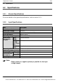
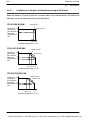
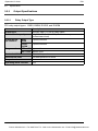
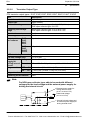
FP0
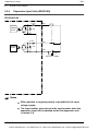
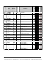
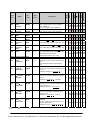
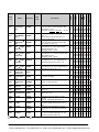
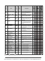
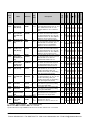
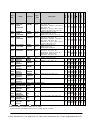
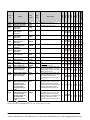
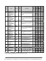
Expansion I/O Units
3.4
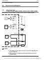
3.4.6
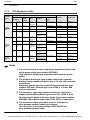
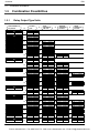
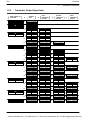
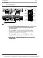
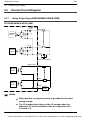
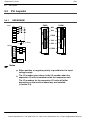
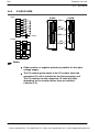
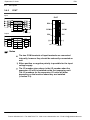
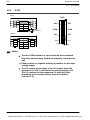
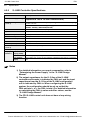
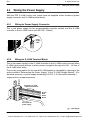
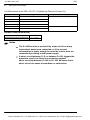
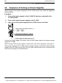
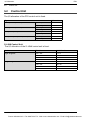
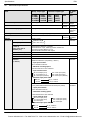
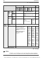
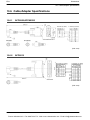
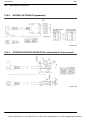
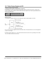
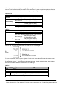
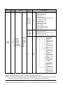
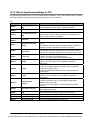
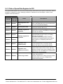
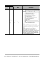
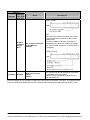
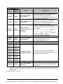
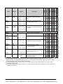
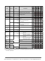
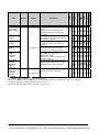
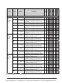
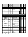
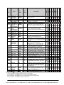
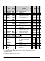
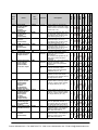
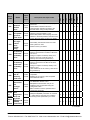
Pin Layouts
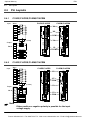
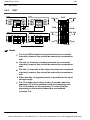
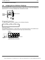
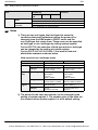
E32P
Input
Input
X20
X22
X24
X26
COM
X21
X23
X25
X27
COM
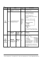
X28
X2A
X2C
X2E
COM
X29
X2B
X2D
X2F
COM
COM
(* Note 1)
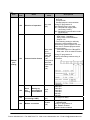
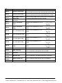
Output
Output
Y20
Y22
Y24
Y26
(+)
Y21
Y23
Y25
Y27
(−)
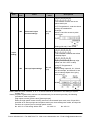
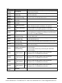
X20 X21
Y20 Y21
Y28
Y2A
Y2C
Y2E
(+)
Y29
Y2B
Y2D
Y2F
(−)
(+) (−)
E32P
X28 X29
COM
Y28 Y29
(+) (−)
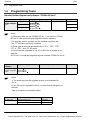
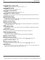
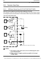
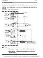
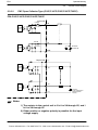
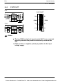
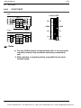
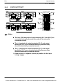
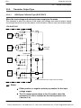
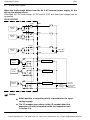
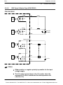
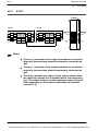
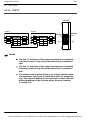
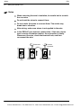
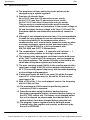
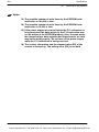
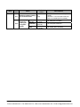
Notes
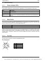
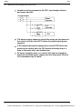
The four COM terminals of input terminals are connected
internally, however they should be externally connected as
well.
The two (+) terminals of output terminals are connected
internally, however they should be externally connected as
well.
The two (−) terminals of the output terminals are internally
connected, however they should be externally connected as
well.
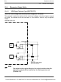
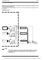
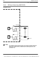
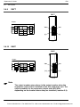
1) Either positive or negative polarity is possible for the input
voltage supply.
The I/O number given above is the I/O number when the
expansion I/O unit is installed as the first expansion unit.
The I/O numbers for the expansion I/O units will differ
depending on the location where they are installed
(*section 5.3).
3 − 23
Phone: 800.894.0412 - Fax: 888.723.4773 - Web: www.ctiautomation.net - Email: [email protected]