1
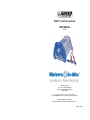
WaSP-F1 Low Flow Controller
USER MANUAL
Issue 3
Waterra UK Limited
Unit 4, r/o 179-189 Stratford Road
Shirley, Solihull, West Midlands B90 3AU
United Kingdom
Tel: +44 (0) 121 733 7743 Fax: +44 (0) 121 733 7746
Email: [email protected] Web: www. Waterra-In-Situ.com
© Copyright Waterra (UK) Limited 2012
Waterra (UK) Limited is a wholly owned subsidiary of In-Situ Inc.
TM07 / 20120814
TM07 / 20120814
SERVICE
CONTENTS
Service Address
Waterra UK Limited
Unit 4, r/o 179-189 Stratford Road
Shirley
Solihull
West Midlands
B90 3AU
United Kingdom
EC Declaration of Conformity ........................................................................ 1
Introduction................................................................................................... 2
Why use the WaSP-F1 Low Flow Controller? ............................................ 2
Explanation of Symbols ............................................................................. 2
Component Identification .............................................................................. 3
Tel: +44 (0) 121 733 7743
Fax: +44 (0) 121 733 7746
Operation ..................................................................................................... 4
Connection to Power Supply ..................................................................... 4
Connection to 12V Submersible Pump or Other Device ............................. 4
Operation .................................................................................................. 4
Email: [email protected]
Website: www.Waterra-In-Situ.com
Troubleshooting ............................................................................................ 5
Specifications ............................................................................................... 6
Guarantee
Service ......................................................................................................... 7
Service Address ........................................................................................ 7
Guarantee ................................................................................................. 7
Warranty Period
This warranty is not transferable.
Waterra (UK) Limited warrants that it will replace or repair at no cost to the
customer any defects in material or workmanship for a period of 1 year from
date of purchase provided that the unit has only had normal use as described
in this manual.
Warranty Exclusions
· Repairs required as a result of accidental damage or use outside the
conditions of normal use as described in this manual
·
Repairs required as a result of any modifications by the user
·
Repairs required on any unit which has been loaned or rented to third
parties by the purchaser
See our Terms & Conditions which can be supplied on request. This does not
affect your Statutory Rights.
For Warranty conditions outside the UK and Ireland, refer to your local
Waterra-In-Situ dealer.
Version 3
7
TM07/20120814
SPECIFICATIONS
EC DECLARATION OF CONFORMITY
It is the policy of Waterra-In-Situ to continually review and update product
design, therefore some details may differ from the actual product sold. All
dimensions are approximate and include protrusions.
Producer
Waterra (UK) Limited
Unit 4, r/o 179-189 Stratford Road
Shirley
Solihull
West Midlands
B90 3AU
Electrical
Input Voltage
12V DC
Output Voltage
0 – 12V DC
Maximum Load
25 Amps
Safety / Protection
Description:
Variable voltage controller to enable low flow pumping with 12V submersible
pumps
Type:
WaSP-F1
Input connection
Reverse polarity protected
Maximum load
Load current limiter set to 25 Amps
Internal protection
Internally fused to 30 Amps
Low input voltage
Unit cut-out for input voltage below 8.3V
High input voltage
Unit cut-out for input voltage above 16V
Environment
Requirements:
Meets the relevant emissions and immunity specifications of:
BS EN 61000-6-2: 2005 and BS EN 61000-6-4: 2001.
Which call up:
BS EN 55022 Class A
BS EN 61000-4-2
BS EN 61000-4-3
BS EN 61000-4-4
Protection
Splash proof case
Dimensions / Weight
Radiated Emissions
Immunity to Electrostatic Discharge
Immunity to Radiated Fields
Immunity to Fast Transient Bursts
Length
25.5 cm
(10”)
Width
14.7 cm
(5.78”)
Height
11.7 cm
(4.6”)
Weight
1.6 kg
(3.5 lbs)
Input cable length
1 metre
(3.3 ft)
Controls
And meets the relevant requirements of:
BS EN 60335: General Requirements for Household and Similar Electrical
Appliances
Status LED
Steady – correct operation
Slow flash – low input voltage warning
Rapid flash – high input voltage warning
Rotary flow control dial
Authority:
On/Off switch
Varies voltage output from 0 to maximum
Connections
Peter Dumble, Technical Director
1
Input (cable)
Twin core cable with insulated crocodile clips
for connection to a 12V DC battery
Output (terminals)
Threaded positive and negative terminal
posts and nuts suitable for crocodile clips or
for cable connection
6
INTRODUCTION
TROUBLESHOOTING
Switch the dial on
Switch the unit off and back on
again
The Flow Control Dial is switched off
The Low Flow Controller has been subjected
to a heavy static electrical discharge
Test the pump by connecting
directly to the battery
There is a problem with the pump
Check the connections
The pump leads are not connected properly
This manual covers the operation and maintenance of the WaSP-F1 Low
Flow Controller. This manual should be considered a permanent part of the
WaSP-F1 Low Flow Controller and should remain with it if it is sold.
If a problem should arise, or if you have any questions, please contact
Waterra UK Ltd.
Waterra UK Limited reserves the right to make changes at any time without
notice and without incurring any obligation.
No part of this publication may be reproduced without written permission.
Why use the WaSP-F1 Low Flow Controller?
The WaSP-F1 Low Flow Controller is an easy to use and robust solution for
progressively varying the voltage supply to a 12V submersible pump in a
precise and controlled way.
The WaSP-F1 Low Flow Controller design features include:
· Universal voltage controller suitable for any non-boosted 12V device with
up to 25 Amps current draw
· Single on/off dial with precision control of flow rate
· Splash proof sealed housing
· Intelligent electronics with built-in safety features
· LED warning signal
· Light-weight (1.6 kg) and compact
· Robust aluminium housing
Explanation of Symbols
The Waterra WaSP-F1 Flow Controller is designed to give safe and
dependable service if operated according to instructions. Read and
understand the Owner’s Manual before operating the Flow Controller.
Failure to do so could result in personal injury or equipment damage.
Pump does not
work
Replace or charge the battery
The Waste Electrical and Electronic Equipment Directive (WEEE
Directive) aims to minimise the impact of electrical and electronic goods
on the environment, by increasing re-use and recycling and reducing the
amount of WEEE going to landfill. It seeks to achieve this by making
producers responsible for financing the collection, treatment, and
recovery of waste electrical equipment, and by obliging distributors to
allow consumers to return their waste equipment free of charge.
CE marking is a declaration by the manufacturer that the product meets
all the appropriate provisions of the relevant legislation implementing
certain European Directives.
On
Reconnect using the correct
way round (Red +, Black -)
The input leads have been connected to the
battery the wrong way round
The battery is discharged
Check the connections
The input leads are not connected to the
battery properly
No output
Off
Use a power source with the
correct input voltage of 12V
The input voltage is greater than 16V and
the Low Flow Controller has cut out to
prevent damage to your pump
No output
Flashes quickly
Replace or charge the battery
The input voltage has dropped below 8.3V
and the Low Flow Controller has cut out to
prevent damage to the battery
No output
Flashes slowly
Remedy
Problem
LED Display
Possible cause
Before contacting Waterra please use the following troubleshooting guide to
resolve common difficulties.
5
2
COMPONENT IDENTIFICATION
OPERATION
Components described elsewhere in this manual are referred to in the
following diagram:
The operation of the WaSP-F1 Low Flow Controller is straightforward.
However, prior to use for the first time, unpack the flow controller and
familiarise yourself with the controls and components as described in this
manual.
Connection to Power Supply
Note: before connection, make sure that the Flow Control Dial (3) is in the Off
position. If a connection is made while the unit is turned on, the pump will
start operating immediately.
4
Connect the WaSP-F1 Low Flow Controller crocodile clips (1) to a 12V DC
power supply e.g. car battery. For longer battery life, Waterra recommend
using a heavy-duty or marine specification battery.
When connecting to the power supply, ensure that the correct polarity is
observed: Red to Positive (+) and Black to Negative (-), and that there is no
possibility of any bare metal touching between the two connections.
3
2
Connection to 12V Submersible Pump or Other Device
+
Connect the cable from the 12V pump to the WaSP-F1 Low Flow Controller
Output Connections (2). Where the pump cable has crocodile clips, clip
these directly onto the output connector posts. For cables that end with bare
wires, loosen the output connector post nuts and then tighten them onto the
ends of the wires.
1
When connecting the pump to the Low Flow Controller, ensure that the
correct polarity is observed and that there is no possibility of any bare metal
touching between any part of the crocodile clips or output connections.
Description
1.
Crocodile Clips
2.
Output Connections
3.
Flow Control Dial
4.
Status LED
Please note: Waterra do not recommend the use of the Low Flow Controller
with pumps that have a voltage booster.
Operation
Once the power supply and pump are connected correctly, turn the Flow
Control Dial (3) from the Off position. The further the dial is turned clockwise,
the higher the output voltage to the pump, up to the maximum output of 12V.
To turn the Low Flow Controller Off, turn the dial anti-clockwise to the Off
position until the dial clicks off.
3
4