1
I
^'"W^-
A COMPUTER BASED DATA ACQUISITION SYSTEM
FOR THE TEXAS TECH TOKAMAK
by
STEVEN ROBERT BECKERICH, B.S. in E.E.
A THESIS
IN
ELECTRICAL ENGINEERING
Submitted to the Graduate Faculty
of Texas Tech University in
Partial Fulfillment of
the Requirements for
the Degree of
MASTER OF SCIENCE
IN
ELECTRICAL ENGINEERING
y/^
^ Approved
Accepted
May 1980
N<3iJ ^
ACKNOWLEDGEMENTS
I would like to thank Dr. Magne Kristiansen and Dr. Marion Hagler
for their support and guidance throughout this endeavor. I would also
like to thank Dr. Boyd Blackwell for serving on my committee and for
his excellent contributions to this project. I wish to thank Dr. Wayne
Ford for serving on my committee and my wife Carol and my sister Sharon
for the editing and typing of this manuscript. Finally, I would like
to thank my fellow graduate students for their advice and assistance
throughout this project.
11
TABLE OF CONTENTS
ACKNOWLEDGMENTS
ii
LIST OF TABLES
v
LIST OF FIGURES
I.
vi
INTRODUCTION
1
II. THE CAMAC STANDARD
6
III.
IV.
2.1
Introduction
6
2.2
The CAf'IAC Crate
7
2.3
The CAMAC Dataway
7
2.4
The Crate Controller
9
2.5
CAMAC Commands
10
2.6
Dataway Timing
10
EQUIPMENT
13
3.1
Introduction
13
3.2
The Host Computer
13
3.3
The DLll Serial Interface
15
3.4
Optical Isolation
17
3.5
The Communications Interface
22
3.6
Terminals
22
3.7
11/04 - CAMAC Interface
25
3.8
The DCC-11 Interface
28
3.9
CAMAC Modules
28
SOFTWARE
36
4.1
Introduction
36
4.2
System Information
36
• ••
111
4.3
System Programs .
39
4.4
Data Disks
40
4.5
The BASIC Language
41
4.6
OVRNEW.BAS
43
4.7
Hardware Configuration File
45
4.8
PLT200.BAS
47
4.9
ST0200.BAS and Support Files
49
4.10
The Data File
57
4.11
Temporary Files
4.12
RED200.BAS
-
g3
V. OPERATING INSTRUCTIONS
VI.
62
65
5.1
Introduction
65
5.2
Turn-on and Bootstrap Procedure
65
5.3
RT-11 Comnands
66
5.4
Creating a Data Disk
67
5.5
Running the Storage Routines
68
5.6
CAmC "F" Commands
69
5.7
System Commands
70
5.8
Recovery From a Crash
79
CONCLUSIONS AND FUTURE IMPROVEMENTS
81
LIST OF REFERENCES
84
APPENDIX A.
85
PROGRAM LISTINGS AND DISCUSSIONS OF STORAGE ROUTINES
APPENDIX B. USER FUNCTION ADDITIONS TO BASIC
115
APPENDIX C.
122
STORAGE ROUTINE COMMANDS
APPENDIX D. AN EXAMPLE DATA ANALYSIS PROGRAM
iv
126
LIST OF TABLES
Table
Page
1-1
Plasma Parameters for the Texas Tech Tokamak
3-1
Components Included in the 11/04 Computer System. . . .
4-1
Directory of Storage Routine System Disk and Formatted
3
14
Data Disk
38
A-1
Entry Points for the Graphics Routines
97
A-2
Subroutines Used in the Storage Routines . . . . . . .
108
C-1
Record Titles and Types Contained in TITLE.REC
124
V
LIST OF FIGURES
Figure
Page
1-1
Block Diagram of Data Acquisition System
2
2-1
CAMAC Crate with Power Supply and Cooling Fans
8
2-2
Timing Diagram of a Dataway Operation
3-1
Remote Halt/Continue Switch and PC Board
3-2
Front Panel of Terminal Selection Board
18
3-3
Schematic of Terminal Selection Circuit
19
3-4
Continuation of Fig. 3-3
20
3-5
Schematic of Optical Isolation Circuit
21
3-6
Front Panel of Communications Interface
23
3-7
Schematic of Communications Interface
24
3-8
Signals on the Unibus
26
3-9
Signals on the Unibus
27
3-10
EMI Induced on Unibus During Tokamak Discharge
29
3-11
Schematic of 6 Channel Analog Buffer
31
3-12
Switch Position Readout Logic for 6 Channel Analog
11
Modifications . 16
Buffer
32
3-13
Block Diagram of 2 Channel Display Driver
34
3-14
Continuation of Fig. 3-13
35
4-1
Flow Diagram of the Initialization Portion of OVRNEW.BAS .
44
4-2(a)
Hardware Configuration File
46
4-2(b)
Typical Format File
46
4-3
Flow Diagram of PLT200.BAS
48
4-4
Flow Diagram of ST0200.BAS
50
vi
n
Figure
Page
4-5
Typical Parameter File
52
4-6
Probe Position and Orientation . . . .
55
4-7
Typical Data Header
59
4-8
Flow Diagram of RED200.BAS
VI1
.k
,
64
CHAPTER I
INTRODUCTION
As experiments and diagnostic methods become more sophisticated,
the investigator is faced with an ever-increasing amount of data to
assimilate and analyze. The data are often in the form of voltage and
current waveforms which may not be meaningful until combined with other
information or transformed mathematically.
Also, data must be archived
in such a way as to be easily retrieved for comparison and analysis.
The advent of digital sampling and control equipment combined with
the falling prices of small computer systems has greatly reduced the
investigator's plight.
Technological advances in magnetic media have
also made the long term storage of large amounts of digital data both
feasible and cost effective.
Once stored in digital form, the data can
be manipulated quickly by a digital computer.
To realize these advan-
tages, a digital data acquisition system, as illustrated in Fig. 1-1,
has been developed for the Texas Tech Tokamak.
The Texas Tech Tokamak is a toroidal plasma research device of
circular cross section intended primarily for the study of wave-plasma
interactions and plasma heating.
The facility consists of the toroidal
vacuum chamber (R = 46 cm, r = 16 cm), a 130 kJ toroidal field bank, a
20 kJ ohmic heating bank (soon to be increased to 30 kJ), and a 2kJ
vertical field bank. Typical plasma parameters are listed in Table 1-1
and extensive documentation of the construction and performance of the
1 2
Texas Tech Tokamak are available in other reports. '
<D
UJ
-J
UJ
(0
N
10
z
z
<
z
o
<n
UJ
z
z
<
z
z
z
<
z
o
0)
UJ
I-
>-
So:
O
«
UJ
-I
?^
< o
=s E
< fe
—o
o
UJ
H 2
> - UJ
CD
i
z
UJ
ui
UJ2
OC
UJ
>
z o
^5
<
X
UJ
^ u.
(0 u.
2
CD CO
I
o
o
I
lO t i
I
T
±
°^
Q:
Ui
-J m u-
UJ u . J
Z 3 Q.
Z <D 2
z
o
o
o
o
OJ
iO
<
S
X
I-
^
O
0)
1
2i
0)
4->.
•-55
c
o
J
t/J
(/I
H
<
^
Z
UJ <9
J
<:
1 2
zUJ Qo:
»- 2
10
o
UI
(3
CSJ
lO
esj
2
-,Z
=
K UJ
UJ UJ
1
to
i-
(0
cr
9; 0=
X o
UJ CO
CD
rt3
UJ
Q:
<
Q.
CO
U
o
CO
ID
(0
fO
CO
_J
<
-» UJ Z
CD
2
cc
UJ (E UJ
O CL 1 -
"" o
Q- O
O
(L
(T
a.
o
1- 2
> UJ
ffl
2
^ CO
CM O
ro 2
BYTE
FLOP
— UJ
UJ
^
^
yc
— 5 $2
m o O
TWARE:
IC
TRAN
RO- I I
>
>
/04
SSOR
CL
O
CL
u . CO o :
^
o
< o <
CO (D u. 2
CT>
TABLE 1-1
Plasma Parameters for the Texas Tech Tokamak
Plasma Current
15 kA
Plasma Duration
10 ms
m'
loop
n^
e
^e
M^I^IL
(max)
1.5 V
1.2 X 10^^
100 - 150 eV
T..
20 - 40 eV
B
7 k6
<j>
cm"^
The main criteria when developing the data acquisition system were
that it be flexible and easily upgraded as the experimental requirements
change. To satisfy these conditions, a Digital Equipment (DEC)
PDP-11/04 was selected as the host computer.
Due to the widespread use
and modular construction of the PDP-11 series computers, a variety of
peripheral equipment is available from many vendors. The 11/04 system
selected includes 32 k-byte of dynamic RAM and a 512 k-byte dual floppy
disk drive. Communication to and from the computer is via a DEC LA36
ASCII printer terminal.
The interface between computer and experiment is accomplished by a
CAMAC crate (described in Ch. II) and a Standard Engineering DCC-11
crate controller (described in Ch. III). The name CAMAC is an acronym
for Computer Automated Measurement and Control and refers to a set of
hardware and software standards which are discussed in detail in Ch. II.
In general, a CAMAC system is a self-contained group of digitizing and
control equipment which in turn can be controlled from, and transfer
data to, a host computer via the crate controller module.
In the
system described by this report, the CAMAC modules have "local" memory
and are capable of storing and displaying the raw data before they are
transferred to the host computer.
Data points can be listed in tabular form on the printer or displayed as waveforms on either of two CRT displays. One display is a
Tektronix 604 monitor which is interfaced directly to the CAMAC
digitizers and is used to review the data presently stored within the
digitizers. This monitor allows the user to determine the validity
of the data before using computer time and disk space to store and
analyze them.
The other CRT display is a Tektronix 4025 graphics
terminal which serves both as a graphics display and as a second
communications terminal to the computer.
With the graphics terminal,
data presently stored in the digitizers can be plotted and compared to
data previously stored on disks. A hard copy can be made of any
graphics or text on the screen of the 4025 terminal via the Tektronix
4631 hard copy unit which connects to the rear of the graphics terminal
and can be controlled from either the terminal or the host computer.
In subsequent chapters, the points touched upon in this brief
overview will be discussed in more detail. The CAMAC Standard is
described in Ch. II and each piece of hardware is discussed in Ch. III.
A thorough understanding of the storage system software, while not
required to use the system, will be necessary in order to make additions
to the routines as requirements change. These programs are discussed
in Ch. IV and in Appendix A. Chapter V is intended to be an orderly set
of user instructions for the data storage routines to move data to and
from disk files.
In closing, Ch. VI discusses some logical areas for
future expansion and improvement of the system.
w^'
CHAPTER II
THE CAMAC STANDARD
Sec. 2.1
Introduction
This chapter is intended as an introduction to the CAMAC Standard
in general and not as a description of the data acquisition system
discussed in the rest of this report. An understanding of this material
is not required to run the present system but may prove helpful to
persons intending to specify new CAMAC equipment or those writing control programs for the equipment.
The CAMAC Standard^ is the result of a combined effort in 1975
by the
Nuclear Instrument Module (NIM) Committee of the U.S. Energy
Research and Development Administration (now DOE) and the ESONE Committee
of European Laboratories.
The CAMAC Standards have also been adopted
by the Institute of Electrical and Electronics Engineers (IEEE).
These
standards were developed to simplify the hardware and software efforts
involved in interfacing between an experiment or processing system and
the diagnostics and control equipment required to monitor the process.
Standardization
of control and data signals within the CAMAC system,
as well as the physical and electrical specifications of the hardware,
allows for simple and inexpensive modification and expansion of the
system as requirements change.
The individual CAMAC modules can usually work on their own (manual
control) but are designed to be computer controlled either from within
the CAMAC system or by an external "host" computer.
A typical system
would include: a CAMAC crate, a host computer, a crate controller/computer interface, and various CAMAC modules to perform the necessary
diagnostic functions.
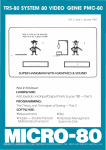
Sec. 2.2
The CAMAC Crate
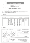
The CAMAC crate, as shown in Fig. 2-1, contains, powers, cools, and
interconnects up to 25 separate modules.
Each module position, or
station, is supplied with ± 6 VDC and + 24 VDC regulated, fused power.
These four supplies are monitored by a meter at the front of the crate.
The modules are supported by tracks along the top and bottom of the
module compartment.
Forced air cooling is supplied by fans housed in
a separate tray below the module compartment.
Additional power supply
lines are connected to each station for +_ 12 VDC, + 200 VDC, and 117 VAC
supplies which are offered as options by many manufacturers but are not
required by the CAMAC Standard.
Sec. 2.3
The CAMAC Dataway
All module stations are interconnected at the rear of the module
compartment by a bus called the Dataway.
The CAMAC Dataway is a multi-
layered printed circuit board which supplies power to each station and
transfers command, data, status, and address information between stations
Connections to the Dataway are made via an 86 contact PC edge card
connector at each of the 25 stations.
Stations 1 to 24 are called
"normal" stations and will accept any CAMAC module while station 25 is
reserved for the crate controller module (discussed in the next
section).
The normal stations (1-24) share common power supply lines.
8
CAMAC
MODULE
25 CAMAC STATIONS
CRATE CONTROLLER
MODULE
POWER
SUPPLY
FAN D R A W E R
Fig. 2-1. CAMAC Crate with Power Supply and Cooling Fans
subaddress lines, data lines, module status lines, and command lines.
Each station has a separate station address line ("N"), and "Look at ME"
line ("LAM", often used to request service) that terminates at the
controller station (25).
Sec. 2.4
The Crate Controller
The crate controller occupies (at least) the two right-most stations
(24 and 25) in the crate. The function of the controller is to initiate
and monitor all Dataway activity. A module can request service by
raising its "Look at Me" line, and can indicate its status to the controller on the "X" and "Q" status lines. The controller also issues
CAMAC commands and acts as a data buffer for transferring data to or
from the modules.
In selecting a crate controller, there are two major
subdivisions to consider; local intelligence vs remote intelligence.
A "smart" crate controller contains local intelligence (usually
in the form of a microprocessor) and local memory and is capable of
storing and executing programs to control the functions of each module.
For communication with devices or computers outside the CAMAC system, a
simple parallel or serial (e.g. the "RS-232" standard) interface is
usually employed.
In contrast to the controller described above, the
"dumb" crate controller has little or no local intelligence and is
primarily to "translate" commands and data, from an external host
computer to the form required by the Dataway and the CAMAC modules.
The type of controller required depends upon the application.
Controllers are available which allow several crates to be controlled,
10
in a serial or parallel arrangement, by a single host computer or
smart crate controller.
The types of data and their rate of transfer
must also be considered when selecting a controller.
If a dumb con-
troller is selected, it must be compatible with the bus structure, the
input/output conventions, and the signal protocol of the host computer.
Sec. 2.5 CAf'IAC Commands
As mentioned in the previous section, the CAMAC modules are controlled via commands issued by the crate controller.
Each module is
addressed by its station number (N). Within each module, any one of
16 subaddresses can be specified by a 4 bit subaddress code (A^,A2)A.,
Ag) generated by the controller.
There are 32 CAMAC commands (called
"F" codes ) which are selected by a 5 bit command code (^i »^2'^4''^S'^16^
and directed to an individual module and subaddress by the (N) and (A)
codes. The response from the module to this command depends upon the
particular piece of equipment being used (an example of the execution of
a CAMAC command is given in the next section).
Sec. 2.6
Dataway Timing
Signals on the Dataway are synchronized by two timing signals
(S,,S«) which are generated by the crate controller and are common to
all stations. A typical Dataway operation is illustrated in Fig. 2-2
and is described in the following example.
Suppose the module in station 13 is a 12 bit analog to digital
converter which stores the results in an internal buffer accessed
through subaddress A(3). After a conversion the ADC loads its buffer
and issues a "Look at Me" signal to the controller.
To transfer the
11
1»
1
1
i
s
k
o
o
o
0>
8
A
OB
o
o
c
o
<T3
0)
o
8
o
o
>>
UI
CO
o
82
^
8
/
IO
to
en
•
O
c
IO
CM
I
CSJ
Oi
co
UJ
oz
<Q:
o
o
CM
bJ
00
UJ
00
o
(T
o
(T
v>
co
1-
1-
12
Information from the module, the crate controller would simultaneously
clear the "Look at Me" signal, and issue an N(13), A(3), and F(0) (read
registers) on the respective Dataway lines. This action corresponds to
tg in Fig. 2-2 where all signals use negative logic (e.g. 0 V = logic 1).
After the F(0) command is issued, the ADC module must gate the contents
of its buffer onto the data lines of the Dataway (and remove its LAM
signal) within 300 ns. The S^ signal is issued at t = 400 ns and gates
the information into the crate controller (or to the host computer).
The
$2 signal, issued at t = 700 ns resets the status lines and signals the
end of the Dataway operation (e.g. may re-arm the ADC for the next sample)
All data and command signals on the Dataway are TTL level negative logic
signals (e.g. logic 1 is < 0.8 V, logic 0 is > 2.0 V ) .
Three special commands, called "common control signals", operate on
all modules simultaneously.
These commands are the initialize (Z),
clear (C), and inhibit (I) signals. The initialize signal is used after
turning on the crate to reset all internal registers to a defined state.
This command has priority over all Dataway operations.
The clear command
is used to reset all I/O registers connected to the Dataway and the inhibit command will halt all activity on the Dataway (without losing information).
As a safeguard against loss of information, the initialize
and clear commands require the S^ signal to be present before they will
execute.
In closing this chapter it should be noted that this material has
only cited
the major aspects of the CAMAC Standards.
Detailed dis-
cussions of the standards are included in the literature of Ref. 3.
CHAPTER III
EQUIPMENT
Sec. 3.1
Introduction
The equipment making up the data acquisition system was chosen for
its flexibility and expandability. As mentioned in Ch. I and shown in
Fig. 1-1, the major components of the system are the PDP-11/04 computer
system, the CAMAC digitizing system, and the Tektronix 4025 graphics
terminal.
In this chapter, each piece of equipment is discussed with
respect to its purpose within the overall system.
References are made
to the existing documentation for detailed electrical descriptions and
options for some of the equipment.
Sec. 3.2
The Host Computer
The main part of the data acquisition system is a Digital Equipment
PDP-11/04 minicomputer which is used to control the CAMAC equipment,
transfer data to and from disk files, and execute software programs to
analyze and display data. The computer was purchased as DEC system
#SR20RRA-LA.
The components of this system are listed in Table 3-1.
The documentation for the 11/04 system includes both operator's instructions for using the system and engineering drawings for trouble
shooting and repair. Those intending to operate the system should become
familiar with the "Introduction to RT-11", the "RT-11 User's Guide", and
the appropriate language reference manual (FORTRAN, BASIC, or ASSEMBLY
LANGUAGE).
The front panel of the computer contains a run/halt switch to halt
the CPU and an LED "run" indicator. By use of this switch, program
13
14
TABLE 3-1
Components of the POP-11/04 Computer System
The 11/04 central processor unit (CPU)
32 kb of active MOS dynamic RAM
512 kb dual floppy disk drive (RXOl)
Bootstrap ROM module (9301-YF)
Parity generator/checker module
DLll-W serial interface board
Unibus terminator (9302)
LA36 printer terminal
RT-11 real time operating system
Documentation kit
15
execution can be Interrupted (e.g. as the Tokamak is being fired,to protect against noise-induced errors) and resumed without loss of information.
Through a slight modification of the front panel PC board and two
additional switches, the halt/run switch has been made available at a
remote location (within the experimental screen room) as well as on the
front panel. These modifications and additions are shown in Fig. 3-1.
Additional LED's on the front panel and in the screen room indicate
which halt switch is enabled.
Sec. 3.3
The DLll Serial Interface
Communication between the computer and the user is via the DLll-W
serial interface board which plugs into the backplane of the computer.
The DLll is a buffered communication interface which allows for the
exchange of parallel information from the computer with serial Information
from the terminal. Also contained on this board is a real time clock
running at the AC line frequency.
This clock can be set by the RT-11
monitor and read by computer programs with a minimum time interval of
16.6 ms (60 Hz). Through microswitches on the PC board, the DLll can be
configured to be compatible with different types of terminals.
Options
include separate transmit and receive data transfer rates (known as
"baud"), odd or even parity, and variable word length.
The DLll can be
configured as either an RS-232 interface or a 20 mA loop interface.
Two terminals are presently available in the data acquisition system,
the LA36 printer terminal and the Tektronix 4025 graphics terminal.
LA36 is a 20 mA loop device while the 4025 is an RS-232 device.
The
To sim-
plify changing from one terminal to the other, the option switches on
the DLll (which resides inside the computer cabinet) have been extended.
16
^
ii
X
s
II I
:»
^
(/I
c
o
o
»o
MOOatflU^
o
o
OQ
a.
(O
3
C
O
4)
rO-M
CO
UJ
0)
o»00
Ul
0.0:
^
H r
—-F
111
*N
<UJ
a- —
(T Ui
u.ae
I
CO
o>
17
via a 40 conductor ribbon cable, to a front panel above the computer.
This front panel switch board is shown in Fig. 3-2 and a schematic is
given in Figs. 3-3, 4.
The switch panel allows the user to select one
of three possible terminals by turning a single three-position switch.
Position 1 is wired for 20 mA loop operation and is dedicated to the LA36.
Position 2 Is wired for RS-232 operation and is dedicated to the 4025.
Position 3 is wired for RS-232 operation but is not dedicated to any one
terminal. The transmit and receive rates (and other options for position
3) are selected Independently for each terminal by miniature switch packs
on the front panel. All other options for positions 1 and 2 have been
hard-wired.
Only one terminal can be transmitting to the computer at any given
time but all three may listen by setting their "echo" switches to the
"ON" position.
Terminals 1 and 2 each have two sockets connected in
parallel; one on the back of the switch panel and one in the experimental
screen room to allow for remote operation.
However, only one terminal
should be installed for each position.
Sec. 3.4
Optical Isolation
Typically, the 4025 terminal is used as a remote terminal at the
experiment.
To protect the terminal against large induced voltages, an
optical isolation circuit has been designed and installed in the RS-232
line between the terminal and the switch panel. A schematic of the
circuit is shown in Fig. 3-5.
The isolator consists of two identical
but electrically isolated circuits,-each containing a transmitter, a
receiver, and a power supply.
The transmitter in each side drives a
18
Si23456789IO
Ul
CO
Od
I II I I I II 1 I
UJ
-I
UJ
I iiii
i
UJ
o
Ul
i[
3 5 0
o.
IO
S
s
i
2 S
UJ
^ S
o
O
o
03
Ul
t »- P
S
0= s5
S.
CO
<
<»
S Q
cr 3 S JS S S ? o i
UJ
s so:
3fw S
o oe ^
c
SI234S6789I0
I I I II I I I I I
Ul«
>
0 0 0w^o 0 0
oo
W Al
OOOCgOoO
a.
UJ
CO
*
*
y
*
»
CM
I
(9
(M
—
CM
o
<
a:
lij
Ul
UJ
(S
1*4
oogggooo
\
o
Ui
Ul
UJ
(O
o
o
ooo^oooo
—«ii<»—Win—«i«»
§ I 2 3 < 4 8 6 7 8 9 IO
en
J 1 1 1 t1 1 1 1 1
01
c
o.
c
o
-./%oOOO
I-
^
CO
K)
<
a:
OJ
CM
fO
UJ
-J
Ul
I-
"oo^^o® 00
»
o
>•
Ul
^
E
UJ
Ul
00 oooo^o
e o
0 0 0 0 0 0
/
CM
I
CO
o
'*Spp^''
19
CO
1
O
IO
• m
O
•
CO
IO
5
*mSU
«.iS«.
:
a. OS
UJ
Ui
o
2i^
l^'
« ^ ^
« ^
C9
oi
^
KJ
*m^
flL Ul
10 <«
•J
UJ <
-J z
««—»
Ui
. SPSl
•my
OSITIO
LECT)
• m •
CSI
UJ
• ^
0
z
3
<
C9
0
••
CO
u
s.
H
co
CL
CO
o
4D
Ui
r—•
0)
O
O
i
CO
•
X
o
E SWI1
•
C,D
I
UJ
CO
u
CO
C
i
CO
0>
I—
O
u
«fU.
o
o
w^^
OS ^
<
•r"
•M
10
01
3
CO
««iSU.
...iS^
CO
4..ISU
<
OS
. . - ^
z
o
CO
I
CO
o>
wt«.
• •
•
H'g
o
UJ
zo
£«
I'
Ooe
•UJ
JB.
M
3
^
^
X
^
" JKWHWfW
20
"*»M»**m*-"^
3 at
Ui o
^g
p8
UJ
M
ZCM[J^
CO
ro
CM
Ui h - * "
cNi
ro
UJ
0 «
^•
ro
it>
(O
CM
o
h-
UJ
CO
52
-.
•—1«
CO
I
CO
!•
o
c
o
3
O
I
CO
O)
-"™5jp^
21
fCDHi-
•»n
Q "Q
K
S^
S^
Sii*.
S4-
t^ p
o
HH»- HH»' i H
m
o00
H'-
Ul
I-
ul
?
3-
(O
CO
O
o
o
o
CJ
to
CO
o
C9
IO
:=
^L
«,l_j
ea
a.
SI!
OS o .
Ul
loO-
^nssssi
3
3
o
a.
l&r^Vil
*"\>^jok/H^'
c
o
O
UJ
H
COS
'o
^ <
CO
CO
xo
Q.
O
Ul<
-JCL
(LCO
IT)
I
CO
^ ; ^
OS
12
«o t l g
S 2
<
CO
O
tJ
OE
>-
o-
I- z
z < o
Ul
Ul
o
^'•
Ui
oe
fOO
M O
i
K
IO
CSJ
CO
i(iH^'
oa.
Z
<
UJ
CL
2O
c^
<
UJ w_
ti
UJ a.
o o.
Ul
UJ
l(IH^
H'-
^H'• HHi
oe
s
IO
H"
00
=
UJ
OS CO
en
22
4N25 opto-isolation IC in the other side. This method provides for at
least 2.5 kV isolation.
Sec. 3.5
The Communications Interface
An interface has been designed to selectively connect between two
terminals and two computers.
This unit also serves to monitor any
activity on the communication lines. The original purpose of the interface was to allow the 11/04 to communicate with the central campus computer (via modem and timeshare lines) but the unit has been useful as
a general purpose monitor.
The front panel of the interface is shown in
Fig. 3-6 and a schematic is given in Fig. 3-7. The unit is typically put
in series with the 4025 terminal but can be used in any RS-232 serial link.
Through switches on the front panel of the interface the operator
can connect either terminal to either computer or have the two computers
talking to each other. Three LED's on the front panel monitor activity
on various data lines and can be used to debug problems in the communication link.
Sec. 3.6
Terminals
The LA36 is a general purpose terminal using a standard ASCII keyboard for input and a 30 character/second impact printer for output.
Input and output transmission rates (baud) must be the same and are switch
selectable for 110, 150, and 300 baud.
Detailed information and main-
tenance procedures for this terminal can be found in the LA36 User's
Manual.
The Tektronix 4025 is a microprocessor-based graphics terminal
using an ASCII keyboard for input and a CRT for output.
The 4025 is
23
LED
INDICATORS
TTY—PDP
FROM
370
r i ENABLE
^ KEYBD.2
FROM
PDP
/ / MONITOR
^ ALL DATA
370—POP
TTY—370
Y 7
MODE SELECT SWITCH
O
DATA
PATH
/ / DISABLE
^ PRINTER \
^
DISABLE
PRINTER 2
(5
OFF
POWER C
j
^-<
V
POWER PILOT LAMP
Fig. 3-6. Front Panel of Communications Interface
24
a;
u
to
»•-
0)
to
o
£
&.
KJ)
to
to
E
u
I
CO
CD
H H>-
>-
l - > -
CSJ
a. o
a.
IO
^•
o
25
capable of dividing the screen into upper and lower areas called the
"workspace" and the "monitor", respectively.
Text from the keyboard or
computer can be directed to either area. Local memory allows the 4025
to store up to ten pages (screens) of text which can then be "scrolled"
on or off the screen using keyboard commands. Other options and features
of the 4025 are discussed in the 4025 User's Manual and the 4025 Programmer's Guide.
Sec. 3.7
11/04 - CAMAC Interface
The circuit boards which make up the 11/04 system are interconnected
by a common backplane called the Unibus. The Unibus consists of 56 signal
lines which carry data and commands to each board within the computer.
For making connections to external devices, the computer backplane is
brought outside the cabinet via an Unibus extension cable. A 14,2 m Unibus
extension cable has been installed between the computer and the CAMAC
crate. Tests were made to ensure that the capacitive loading of the cable
did not degrade the rise and fall times of the signals on the bus. The
results are shown in the oscillographs of Figs. 3-8 and 3-9. Shot 3-8(a)
depicts the signals on an address line without the extension cable. Shot
3-8(b) shows the effect of the unterminated extension cable. Shot 3-9(a)
and (b) show the response on the bus with the Unibus terminator board
properly installed in the connector block at the CAMAC crate. The rise
and fall times to H L levels (0.8 V - 2.0 V) are about 20 ns and are
almost identical to the response of the unextended backplane.
To protect the system from electromagnetic interference (EMI) the
Unibus extension cable and the remote terminal lines are enclosed in a
26
Vertical
Scale
1 V/cm
(a) Standard Bus, No Extension
Vertical
Scale
1 V/cm
(b) Extended Bus, Unterminated
Fig. 3-8.
Signals on the Unibus
27
Vertical
Scale
1 V/cm
(a) Bus Extended and Terminated
Vertical
Scale
1 V/cm
(b) Expanded Time Scale of (a)
Fig. 3-9.
Signals on the Unibus
26
Vertical
Scale
1 V/cm
(a) Standard Bus, No Extension
Vertical
Scale
1 V/cm
(b) Extended Bus, Unterminated
Fig. 3-8.
Signals on the Unibus
T
27
Vertical
Scale
1 V/cm
(a) Bus Extended and Terminated
Vertical
Scale
1 V/cm
(b) Expanded Time Scale of (a)
Fig. 3-9.
Signals on the Unibus
28
continous conduit connecting the computer cabinet to the experimental screen room where the CAMAC crate resides. The conduit is approximately 11 m
long and is constructed from .3 m. length of .102 m O.D.
EMT electrical conduit.
Tokamak was fired.
Noise on the Unibus was measured while the
The results are shown in Fig. 3-10. The peak
noise voltage was found to be about 0.75 V, well below the 1.5 V noise
margin of the Unibus.
Sec. 3.8 The DCC-11 Interface
The Unibus extension cable has effectively brought the resources
of the 11/04 to the experimental screen room. As discussed in Sec. 2.3
the CAMAC modules are interconnected by the Dataway which is not directly compatible with the Unibus. A Standard Engineering model DCC-11
crate controller is used to translate data and command signals between
the Dataway and the Unibus. A detailed explanation of this interface
can be found in the DCC-11 User's Manual.
Briefly, the DCC-11 is a
"dumb" crate controller that maps the CAMAC station addresses and subaddresses onto a block of 1024 Unibus addresses.
Each address and sub-
address (and the data they contain) can be uniquely accessed by the
11/04 instruction set.
Sec. 3.9
CAMAC Modules
Data from the experiment are transfered to the computer through
CAMAC modules.
Presently incorporated in the sustem are two 8 channel
waveform digitizers for time resolved data and a 32 channel scanning
DVM for single sample data.
Nine analog buffers have been built (a 3
channel prototype and a 6 channel final version) to amplify and filter
29
Verti cal
Scale
1 V/cm
Fig. 3-10.
EMI Induced on Unibus During Tokamak
Discharge
30
the signals (if necessary) before digitizing.
A 2 channel driver has
also been built to display data on a Tektronix 604 monitor.
The two 8 channel digitizers are LeCroy model 2264, each occupying
three CAfdAC stations.
The model 2264 consists of a single ADC which is
multiplexed over 1 to 3 inputs. The maximum sampling rate is 4 MHz for
a single channel and 500 kHz for 8 channels.
Each of these digitizers
requires a LeCroy model 3800/8 buffer memory module for storing the
digitized data.
Front panel controls allow the user to select the
sample rate and the number of channels to sample.
These units also
have the ability to record pre-trigger data as well as post-trigger
data. The front panel switch positions can be read (but not set) by
the controller.
The 9 buffer amplifiers have been built to provide a 1 Mn input
impedance for the diagnostics and 50 a drive capability to accommodate
the 8 channel digitizers.
The buffers also provide input over-voltage
protection, low pass filtering, and switch selectable gain.
The 6
channel version has 12 gain settings from XO.Ol to XlOO and includes a
logic circuit which allows the controller to read the setting of the
gain switch for each channel. The schematic for a typical buffer
channel is shown in Fig. 3-11 and the position readout logic is shown
in Fig. 3-12.
The 8 channel digitizers also include a DAC circuit to reconstruct
the data stored in the buffer memory for display on an oscilloscope.
A
2 channel driver has been built to display this reconstructed data on a
Tektronix 604 monitor.
The driver includes vertical position control,
XI or XIO vertical gain, and a choice of continuous or single sweep.
r
GAIN
eJ t o d x ^ d d
— cafiS o
)
1%)
31
s
o
H
•»>
<'><^ . . .
00 K5eJ 1 1 f
^
o
co
CO ^^^
to o o o o o
Ul ^ CSJ l O O i O o o
— CM mCM IO o
UL
oe
""CMio
a
CO
(E
CL
o
1
tr
5
S o >
CO
o
UL
Z
<
C9
h- 00 0 > 0 — <M
^" — ^"
IO
CM IO
IO
o o — <^loo
•^ O O 0 < M a» CM
o. CM <9» O CO f ) CM
O 00 IO CM
^,-,_
c!
0)
.
oz
.
•
• . ^
— CM IO
3
CO
CO
o
a.
_
CM r o ^ lO (O
O
c
a;
c
c
«o
o
*^
O
U
E
<u
u
00
CO
Ul
>
IO
I<
o
+CF
o
•M—02
<
CD
o
Ul
¥ ? /.
«o
<0
UJ
UJ
z
o
o
a.
o
o
I
I
o.
I
75 «
^4lHi'
-AAV-il«
S (t) 1|. 2 g
32
6
Ai:
12 POSITION
SN7442
4X10
DECODER
J.
-^
2,
r4"
T
i"
3.3k
'2
POSITIONS
I to 9
I
M i l l !
SN74I47
10X4
ENCODER
I.C.'S
2 INPUT NOR 7402
QUAD 2 INPUT OPEN COLLECTOR NOR 74LS33
QUAD 2 INPUT OPEN COLLECTOR NAND 7403
DUAL 4 INPUT NAND 7420
8 INPUT NAND 7430
A : QUAD
B:
C:
D,E:
F:
D.C. POWER FROM CAMAC DATAWAY
Fig. 3-12.
Switch Position Readout Logic for 6 Channel Analog Buffer
p^
33
Also, variable sweep time and a delayed trigger feature allows any
portion of the waveform to be expanded in time. A block diagram of
the display driver is shown in Figs. 3-13 and 3-14.
The final module in the present system is a LeCroy model 2232A,
32 channel,scanning DVM.
This unit contains a single ADC which is
multiplexed over the 32 inputs. The voltage at each input is converted
to a 12 bit binary word and stored in a local 32 word X 12 bit buffer
memory.
With the present configuration only 5 of the 25 CAMAC stations
are free for future expansion. Many of the modules, however, draw only
their DC power from the crate and make no connection to the Dataway.
These modules could reside outside the crate which would then leave 13
stations free for future use.
••J5^-
34
Qx
UJ
si
_|CO
UJ
. >
&^
o
>»
IO
I/)
0)
c
IO
CM
«•-
o
to
s.
to
u
o
CO
I
CO
•
en
35
*-
• £
o
U l l 3
o o — o
o
o
=
^
UJ . ^ ^
i l "=^
ujf- o.
<—
CM
Q >
^co O
S * o
S o-u.
IO
M K- I k
OS
o
o
CO
I—I
I
CO
UJ
•a.
H"
TJ
o
HJ
Z 2
Hoc u.
t 0 '*5 z 0
II
H
> >
10 ^
••
>
00
^ V
H
UJ
en
o
^
0
c
o
cc
>-
CON
o
CO
to
C
o
UJ
UJ
I
CO
co
OQ
0
0
.1o
a.
35
""
>-
CO ~
J ^ CL
UJ Z Q.
<
0
UJ ^
z
^ a
0
K S o^
0
to 0
< >- u.
u. S3
UJ 1 <
z UJ UJ
H 0 oo
a>
CHAPTER lY
SOFTWARE
Sec. 4.1
Introduction
A set of BASIC subroutines has been written to control the hardware
described in Ch. III. These subroutines have been combined with data
manipulation and error checking routines to form a versatile, expandable,
data storage program. The program is structured as a command interpreter
and address table. Commands are executed by subroutines, the starting
addresses of which are stored in the address table within the main program.
When a comnand is entered from the keyboard, the program searches the
address table for the start address of the corresponding subroutine, executes the subroutine, and returns to the main program to wait for the next
command. The subroutine, when necessary, may request additional information from the operator while it is executing. As new equipment is acquired,
new command subroutines can be added anywhere in the main program and their
addresses added to the address table. This chapter will discuss the
structure and flow of the software to allow future users to make additions
without re-writing the entire program,while Ch. V is a set of instructions
for loading and running the storage program.
Sec. 4.2
System Information
Some knowledge of the 11/04 system structure is required in order
to understand the storing routines. Those points that pertain to the
routines are discussed here. For more complete information the reader is
referred to the 11/04 documentation kit.
36
37
The storage routines are written to run on the 11/04 system (with
the equipment listed in Table 3-1) and a Tektronix 4025 graphics terminal.
The RXOl disk drive is a file structured device. Files on a disk can be
created and manipulated by the RT-11 monitor and by an executing program.
A "directory" file, installed on each disk, contains the title, length,
creation date, and position (on the disk) of all files on that disk. A
program stored on a disk must be downloaded into active memory before it
can be executed.
Loading a program does not alter, the file stored on disk.
Space on a floppy disk is allocated in "blocks" where a block is
512 bytes. A standard disk, after being "Initialized", will contain 480
free blocks. The RT-11 "initialize" command prepares a disk for use in
the 11/04 system by creating a directory (or erasing the existing directory
If the disk has been used before). The-two disk drives are labeled DXO
and DXl where "DX" indicates an RXOl drive.
In the default configuration,
DXO is the system disk containing the RT-11 monitor programs and device
handlers while DXl is used for general purpose storage.
A directory of the disks used with the storage routines is shown
in Table 4-1.
Each entry in the directory includes the title, the length
(in blocks), and the creation date (or last modification date).
The
system disk (in DXO) contains the required RT-11 monitor programs and
the data storage routines. The disk in drive DXl, as shown in Table 4-1,
is a specially formatted disk for storing data files.
Each of the files
on this disk has a specific purpose that will be discussed in later sections.
File titles consist of two parts separated by a period. The first
part is a 1-6 character name usually chosen to describe the contents or
function of the file. The second part is a 1-3 character "type". The
\
38
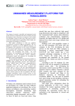
TABLE 4-1
Directory of Storage Routine System Disk and Formatted Data Disk
02-Jan>80
CATDXR.BAS
CATDZR.COH
CLRtOU.BAS
CONP-XG.ZNF
CKEATCBAS
DATA .HED
DIR
.SAV
OUHMY .BAS
DUP
.SAV
SXHNSJ.SYS
EDBAS .LST
ED:T .SAU
FZXREIt.BAS
FORMAT.FMT
GPKEY8.LST
6RA200.BAS
LENGTH.BAS
LOOREC.BAS
I1ACHIN.DAT
3 Ol-Nov-79
1 06-NOV-79
1 12-0et-79
1 18-0et-79
3 17-0ct-79
8 07-NOV-79
17 ll-M»r-78
1 Oe-Nov-79
21 2«-«»r-78
63 ll-Mar-78
•» 22-Haw-79
19 ll-M«r-78
3 24-0et-79
1 24-0ct-79
1 05-S«.»-79
•
*» O:-Nov-79
1 15-0ct-79
2 24-0et-79
7 07-NOV-79
2 ai-M»r-78
NL
.srs
39 Fil«Sf 316 BlecKs
164 Fr»« blocks
184
103
260
271
264
362
144
193
123
38
180
161
309
284
191
328
261
282
330
105
0
.SAV
OVRNEW.BAS
PZP
.SAV
PLT200.BAS
RADOOl.FMT
RA0002.FMT
RA0003.FHT
RADOOS.FMT
RAD006.FMT
REAB2 .BAS
RED200.BAS
RTllED.LST
STARTS.COM
ST0200.BAS
STRZF .BAS
SWAP .SYS
TITLE .REC
TITLE .TXT
TT
.SYS
20-S«i»-79
08-NOV-79
ll-H«r-78
Ol-Nov-79
18-0et-79
23-0ct-79
24-Gct-79
07-NOV-79
2 07-NOV-79
•» 24-0et-79
10 24-0ct-79
2 l3-Jul-79
1 l7-0et-79
14 08-NOV-79
1 02-Oct-79
• 24 ll-««p-78
1 03-0ct-79
1 25-0ct-79
2 ll-M»r-78
40
25
16
9
•>
1
206
370
107
319
262
275
273
276
278
280
299
182
250
423
267
14
247
270
101
System Disk DXO
02-J«n-80
TITLE .TXT
1 19-D»e-79
INITIA.LIZ
1 19-D«c-79
< UNUSEIi >
473
3 Files* 4 Blocks
476 Frmm blocks
14
18
21
< UNUSEII
CATALO.G
2 l9-D»c-79
15
19
Data Disk DXl
Each entry includes: the title and type, the length, the
creation or last modification date, and the position on the disk.
In this example, no data files had been recorded.
19
file type can be chosen arbitrarily but the RT-11 monitor is programmed to
recognize certain default types.^
Files on the system disk in Table 4-1 fall Into three categories:
1) Those files required by the RT-11 monitor
2) Those files required to run the storage routines
3) Often used support programs
Files in tfte first group Include:
SWAP. SAV
n.SYS
DXMNSJ.SYS
PIP. SAY
DUP.SAV
DIR.SAV
STARTS.COM
TITLE.TXT
Files in the second group Include:
O.SAV
CONFIG.INF
FORMAT.FMT f'lACHIN.DAT
ST0200.BAS
GRA200.BAS PLT200.BAS
OVRNEW.BAS
FIXRED.BAS
RED200.BAS
DUMMY.BAS
DATA.HED
CLRLOW.BAS
The rest of the files on DXO are useful support programs which are kept
on the system disk for convenience but could be removed if more room were
needed on the system disk.
Sec. 4.3
System Programs
All of the files in group 1 with the exception of TITLE.TXT are
RT-11 system files and are discussed in the RT-11 documentation. The use
of the TITLE.TXT file is a local convention which was introduced to aid
in disk identification. The TITLE.TXT file is a one block text file containing the disk name and number (if applicable) and a brief description
of the contents or purpose of the disk. By opening and reading this file,
a computer program or remote operator can determine what disks are in
each drive.
40
Sec. 4.4
Data Disks
Before a blank disk can be used, it must be formatted by the RT-11
"initialize" command.
If a disk is going to be used as a data disk for
the storage routines it must also be formatted by the "CREATE.BAS" program
which creates the files shown in Table 4-1. The title of a data disk will
always have the form:
DAxxx
(e.g.
DA006)
where "xxx" is a three digit sequence number. The title file will also
contain the initialization date and any comment (up to 450 characters) the
operator wished to make. The disk title and initialization date should
also be put on the protective cover of the disk.
When a file is copied or edited, it may be moved to a new position
on the disk. Since the "INITIA.LIZ" and "CATALO.G" files are accessed
quite often, a 3-block blank space has been left near the top of the data
disk for these files to move into to prevent them from mixing with the
data files and leaving behind holes of wasted disk space. Spaces almost
as large as a data file can be wasted in this way. A listing of the
"CREATE.BAS" program and a line by line discussion is included in Appendix A.
The "INITIA.LIZ" file on the data disk contains the date and shot
number of the last data file stored on that disk, so that shots can be automatically numbered in the correct sequence, even if the computer is turned
off (or crashes) during an experiment.
Because "INITIA.LIZ" is updated
only after each shot has been stored, it is possible that the computer may
stop (crash) after a valid data file is stored, but before "INITIA.LIZ" is
updated.
To minimize the chance of losing a data file this way, the soft-
ware asks the operator to verify the shot number if the program is restarted
41
The "CATALO.G" file on the data disk will contain a directory of all
the data files on that disk. This file is loaded at the end of the day by
a two step process. First, in RT-11, the "CATDIR.COM" command file is
executed to extract the directory information from the data disk and deposit It in a temporary file on the system disk. Then in BASIC, the
program "CATDIR.BAS" is executed to transfer the directory information
into the catalog file on the data disk.
The file name for each data file is created by the storage routine
which combines the date and the shot number, as follows:
File name = YYMMDD.SHT#
Where:
YY = the last two digits of the year
MM = the number of the month (1-12)
DD = the day of the month (1-31)
Zeros are added if necessary so that the file name always has 9 characters.
Sec. 4.5
The BASIC Language
The file "O.SAV" on the system disk is the BASIC interpreter and
must be loaded into active memory before a BASIC program can be run. The
original version was DEC BASIC/RT-11 VOl B. Some new commands have been
linked^ into BASIC to allow for CAMAC operations. These commands are in
the form of callable functions and include:
"PEEK"
to examine a word in memory
"POKE"
to modify a word in memory
"GETB" to examine a byte in memory
"STOB" to modify a byte in memory
"FREM"
to determine the amount and location of free memory
"EXEC"
to execute a machine language subroutine loaded into
42
memory by the "POKE" function
"FAST"
a special purpose machine language routine for reading
data from the LeCroy 2264 digitizers
The memory accessing functions (PEEK, POKE, GETB, and STOB) are
required by the DCC-11 controller in order to execute "F" commands and
common control commands (as discussed in Sec. 2.5). The method by which
the commands are executed is discussed in the DCC-11 User's Manual. The
"FAST" routine simplifies the reading of data and status information from
the waveform digitizers. The "FREM", "EXEC", and "POKE" functions allow
machine language routines to be loaded and executed by a BASIC program.
Listings of the macro programs for these functions are included in
Appendix B.
Instructions for using these functions have been added to
the BASIC User's Manual.
In order to run the storage routines the operator must be sure the
copy of BASIC on the system disk has been modified to include these
functions.
When BASIC is downloaded, the message "USER FUNCTIONS LOADED"
must appear on the terminal.
The BASIC programs and other files which make up the storage routines
are:
DATA.HED
CONFIG.INF
FORMAT.FMT
MACHIN.DAT
PLT200.BAS
OVRNEW.BAS
ST0200.BAS
RED200.BAS
CLRLOW.BAS
GRA200.BAS
FIXRED.BAS
DUMMY.BAS
Each file with a .BAS type is a BASIC program which is overlaid onto the
main calling program, "OVRNEW.BAS".
The result of an overlay is the same
as if the new program were typed in from the keyboard.
Any old lines with
corresponding line numbers in the overlay will be replaced by the new lines.
ik...
43
All variable values and dimension statements are preserved and execution
resumes at the next line number following the overlay statement.
The storage programs can be divided into four major functions: the
main calling program (OVRNEW.BAS), the plotting program (PLT200.BAS), the
the storing program (ST0200.BAS), and the data file reading program
(RED200.BAS).
Appendix A.
A listing and discussion of each program is included in
Each segment is written so that all overlaying is done
between line numbers 20050 and 21350 with increments of 10 in each segment.
By doing this, the lower portion of the main program is made common to
all segments.
Sec. 4.6
OVRNEW.BAS
The main calling program contains the command address table, most
of the simple command subroutines, and an initialization routine which
erases itself after execution.
This routine, residing in the first
portion of the program (lines 10-980), checks that the 11/04 system time
and date are set.
The routine also checks and updates the "INITIA.LIZ"
file on the data disk.
If errors are found, they are logged on the ter-
minal and the program halts. The operator must then correct any errors
that occurred and re-run the program.
When no errors are found, the
initialization routine prints a message warning the operator not to use
the run command again, without reloading the program from the disk, and
prints the hardware configuration file (discussed in Sec. 4.7) into the
workspace of the 4025. The initialization routine also sets a default crate
address and station number (determined by line 910), and then erases the
first 31 lines (10-980) of the program and waits for input from the terminal.
A flow chart of this chain of events is shown in Fig. 4-1.
44
C
RUN
OVRNEW.BAS
)
1
DISPLAY
ERRORS
CHECK SYSTEM
TIME AND DATE
PRINT ERRORS
r
I
DISK
DISPLAY
ERRORS
CHECK
"iNmALIZE" FILE
ON DATA DISK
FOR DATE AND
SHOT NUMBER.
STOP IF ERRORS
INITIA.LIZ
FILE ON
DATA DISK
I
/ HARDWARE
\
IcONFIGURATION/^"
PRINT SYSTEM
CONFIGURATION
INFORMATION
CONFIG. INF
FILE ON
SYSTEM DISK
SET CONSTANTS
AND DEFAULT
VALUES
(
DO NOT RE-RlX.
LINES 10-960
\ ^
HAVE BEEN
/ "
ERASED
y /
PRINT RE-RUN
WARNING.
OVRLAY CLRLOW
CLRLOW.BAS
WAIT FOR USER
TO ENTER
COMMAND
Fig. 4-1.
Flow Diagram of the Initialization Portion of OVRNEW.BAS
45
Erasing a portion of a program is accomplished by overlaying a file
(CLRLOW.BAS) that contains line numbers alone, without statements. As
this file is overlayed, each corresponding line in the existing program
is erased.
Overlays affect only the active memory and cannot modify the
file on disk.
Sec. 4.7
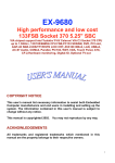
Hardware Configuration File
The hardware configuration file "CONFIG.INF" is printed into the
workspace for the operator to review, and check against the actual configuration of the CAMAC crate. This file contains information about the
CAMAC modules and their position within the crate and is used by the store
routine. A typical configuration file is shown in Fig. 4-2(a).
Each CAMAC
module is identified by a unique unit number and by its TTU inventory number. The crate and station numbers describe a module's location within
the CAMAC system while the type and bus numbers indicate the kind of
equipment used.
The post-trigger entry refers to the 2264 digitizers and
indicates whether the module is internally jumpered so that the number of
post-trigger samples indicated by the front panel switch is read directly,
or is multiplied by two (e.g. twice as many post-trigger samples as indicated by the switch).
The bus number entry allows the system to include
other than CAMAC equipment (583 bus), but no software to support other
buses had been developed at the time of writing.
At this point, the program has printed "ENTER COmAND" on the
terminal and is waiting for input. When a command is entered the program tries to match the first three letters (if there are that many)
with the three letter commands catalogued in the branch table.
If no
match is found, the first letter of the entry is compared against single
46
03-JAN->«0 COPY or COMTXCINFt OTTXOM X
UNIT • f
tf
3»
3t
4t
LFRXMT Wl :Bii
BUS • ff CRATE « f SLOT • fHNF. TT^#» POSTRI6 »SERIAL •
22A4f
2i
*t
1A943A
383 •
It
2»
22*4 •
IA999Z
383 •
1«»
2*
l*»t94
2232.1*
2f
1S»
00*
383 •
0»
OOr
00*
00
oo»
OOt
(a) Hardware Configuration File
02-JAH-80 COPY OF RADOOA.FMT* OPTION I
FORHT* tOF REC
DATE
2001*
*»
7*1107
TYPE UMIT CHML
BAIH
30*
2*
5* 31.1
20*
2»
1»
*
21*
2*
3*
1
113*
1*
2*
I
114*
1*
3*
1
103*
1»
!•
*
OFST
1*
0*
0*
0*
0*
0*
LPRXMT VIIB*
•OF SHPL
IST-TM
CAT ID*
236*
-2000*
0*
0*
234*
-2000*
0*
•0*
234*
-2000*
0*
0*
1024*
0*
4*
103*
1024*
0*
4*
103*
1024*
0*
3*
103*
LST- •TM
(b) Typical Format File
Fig. 4-2.
Store Routine Information Files
0*
0*
0*
0*
0*
0*
STEP
50
SO
30
2.5
2.3
2.3
47
letter commands in the branch table.
If no match is found in either group,
the program reprints "ENTER COMMAND" and again waits for input. A list of
available commands and their meaning is given in Appendix C.
Sec. 4.8
PLT200.BAS
When OVRNEW.BAS is loaded into memory, it contains the "PLT200.BAS"
program residing in lines 20050 to 20990. Note that this is the space
where all overlays will occur.' The PLT200 program responds to the "G" or
"GRAPH" command and will plot data, presently in the CAMAC buffer, on the
graphics terminal. The operator has control over the size and scale of
the graph, the number of points plotted, and the type of line used (solid,
dotted, etc.).
Several graphs may be drawn in separate portions of the
screen or can be drawn on the same set of axes. A flow chart of the
PLT200 program is shown in Fig. 4-3 and a listing and description are
Included in Appendix A.
Lines 20050 - 20240 of PLT200.BAS form a driving program for a set
of general purpose graphics subroutines residing in lines 20250-20990.
The graphics routines are written to drive the 4025 graphics terminal.
Options, such as log or linear scales, multiple or overlayed graphs, are
available. These general purpose routines are normally located in lines
17000-19700 but have been renumbered so as to coincide with the overlay
area of the storage routines.
Instructions for using these graphics
routines have been added to the BASIC Language Reference Manual. The
new entry points for the renumbered graphics routines are included in
Appendix A.
w^
4S
FIND ADDRESS
OF GRAPH
ENTER GRAPH
COMMAND
ROUTINE AND
EXECUTE
DISK
OVERLAY
PLT200.BAS
IF NECESSARY
CHECK CRATE
GET NUMBER
OF CHANNELS
SAMPLED
ENTER
PARAMETERS
FROM USER
ENTER
CHANNEL #
a
# 0 F SAMPLES
READ EACH
POINT FROM
CRATE AND PLOT
ON 4 0 2 3
1
WAIT FOR
NEXT COMMAND
Fig. 4-3.
Flow Diagram of ?L'200.5AS
PLT200.BAS
OR
GRA200.BAS
7
i
49
S e c 4.9
ST0200.BAS and Support Files
The longest and most involved overlay is "ST0200.BAS" occupying
lines 20050 to 21350. This routine is downloaded in response to the "STO"
or "STORE" command and is capable of reading and storing various types of
data from many different sources. The data are stored in virtual files
(discussed in Sec. 4.10) on the data disk. A data file can be up to 128
blocks long (about 30,000 data points) provided that sufficient space is
available on the disk. The first few lines of each data file contain information describing the length of the file and the I.D. number (version
number) of the store program that created it.
For flexibility, the store program acts mainly as an assembler getting most of its information from the CAMAC crate and from four support
files located on the system disk. These four files, which may be modified as the experiment changes, include: a hardware configuration file
"CONFIG.INF", a machine parameter file "MACHIN.DAT", a collection of
descriptive titles for typical Tokamak diagnostics "TITLE.REC", and a file
to determine what and how much data is to be stored, called a Format file.
Several Format files, corresponding to different experiments, can be
stored on the system disk. The operator selects a Format file by entering
its title which will always have the form "NAME.FMT" where "NAME" is a 1-6
character file name given by the operator.
A flow chart of the store
routine is shown in Fig. 4-4.
The configuration file, as discussed in Sec. 4-7, informs the
store routine as to what CAMAC hardware is available and its location
within the system.
Only one "CONFIG.INF" should be on the system disk and
should only require modifications when new equipment is acquired or present
50
TERMINAL
FIND ADDRESS
OF STORE
ROUTINE AND
EXECUTE
ENTER STORE
COMMAND
DISK
OVERLAY
STO200
IF NECESSARY
ASSEMBLE
USER SUPPLIED
INFORMATION
ANSWER
DIALOGUE
STO 200. BAS
/cCONFIG. FILE
/PARAM. FILE
1 FORMAT FILE
\ TITLE FILE
^
ERROR CHECK
DISPLAY
RESULTS
DISPLAY
EXTRACT DATA
FROM CRATE
TRANSFER TO
DISK.
DISPLAY STATUS
DISPLAY
DATA FILE
WAIT FOR
NEXT COMMAND
Fig. 4-4.
Flow Diagram of ST0200.BAS
51
equipment is relocated.
The configuration file is shown in Fig. 4-2(a).
The record title file "TITLE.REC" contains a three digit "Type"
number and title (up to 12 characters) for each diagnostic on the experiment.
This file Insures that all records of the same type will have
exactly the same title in the data file; for example:
030, I PLASMA
(plasma current)
020, COS POS
(cosine position coil)
If a title for a record is not found in the title file, the message "TITLE
NOT FOUND" is written into the data file. Record types and titles may be
added to the title file by using the "TITLE" command in the main program.
The types and titles presently included are listed in Appendix C.
The parameter file contains information as to how the experiment is
set up, such as bank voltages, trigger times, gas pressures, and magnetic
field probe data. The parameter file is copied into the workspace of the
4025 terminal, where the operator can modify or replace the file before
each shot. A typical parameter file is shown in Fig. 4-5.
The version
of the parameter file currently in the workspace is used in the data
storage procedure.
The first few lines of the parameter file contain information about
the size and contents of the file. The abbreviated headings in the second line stand for:
LNS:
total number of lines in the parameter file including blank
lines and headings
TYP:
an I.D. number for this particular parameter file; if modifications are made, this number should be changed
02-jMi-ao coFY or PMWII.LST* OPTION I
3
4
s
A
7
8
9
10
11
12
13
14
IS
14
17
18
19
20
21
23
24
23
24
27
28
29
30
31
32
33
34
35
34
37
38
39
40
41
42
43
44
43
44
47
48
49
SO
31
32
53
34
35
34
37
38
39
60
41
42
52
LPRXNT Vi:8B
NACHINC PMAHCTCRS
LNS TYP CAT LEN OFST
042*1002* 8* 8* 3*
POSITION INFO
CAT OFS TLN OLN
101* IS* 3* 3*
t02» 21* 3* 2*
103* 24* 3* 4f
104f 33* 3* S*
lOS* 41* 3* S*
104* 49* 3* 1*
107* S3* 3* 1*
900* S4* 2* 2*
••••—•LAST LINE OF PARAMETER FILE HEADER'
•START USER INFORNATION-
CHAMBER
GAS XO * PRESSURE<T) QAS NAHE
999*
2.00E-07*BASE
101*
S.aOE-03*D2 FILL
00*
O.OOE-OO*
PUFF FILL
VALVE ID # TINE (4>T0) PRESSURE(T) GAS ID •
GAS NAME
01*
00*
O.OE'OO*
101*
02
00*
00*
O.OE-OOf
00*
CANAC TRIGGER TIMES (USEO
UNIT •
TRIG.TIHEOTO)
1*
13300
13300
«:*
00
3*
00
4*
BANK VOLTAGES (KV)
SLOW
TRIG(-»'TO>USEC BANK NAME
BANK ID «*
FAST
*
O.S*
l3300»aHMIC HEAT.
101*
1.1*
0.04*
13300*VERT. FIELD
102*
0.20*
0*
11400*PREiaNIZER
103*
13.0*
0*
3130*TOR. FIELD
104*
4.4*
0*
31S0*RA0.(HENRY)
lOS*
4.0E-04*
PROBES
PROBE ID« *T0R. P0S(0)fP0L. POS(0)fRA0.POS(CM>*0RIENTATI0N
3*
40*
180*
13*
0
4>
40*
270*
0»
0
»
*
*
*
»
»
»
*
*
ANTENNA
ANTEN. ID* *T0R. PQS(D)*P0L. POS(D)* FREQ.(MHZ)fCURRENT(A PP)
180*
8.0*
SO.O
0.0*
101*
SPECTROMETER
SPEC. ID*
UAVELEN.(A)fPM VOLT(KV)fSLIT
0.0*
101*
3441.0*
(UM)*SLIT
10.0*
(UN)*
10.0*
COMMENTS
TYPICAL FAST UAVE PROFILE SHOT
END PARM FILE
Fig. 4-5.
Typical Parameter File
FILTER ID*
100
»^.
53
CAT: the number of categories in the user Information section
LEN: the length (number of data lines) of the position information
category
OFST: the offset to the first data line of the position information
category
The abbreviated headings in the position information category (line
6) are:
CAT:
the category number of each section of the user information;
the comment section (900) should always come at the end of
the file
OFST: the offset to the first data line of that category
TLN: number of lines in the category title
DLN: number of data lines in the category
The offset numbers in these two categories are used by data retrieval and analysis routines to access data quickly. The offset numbers
are calculated from the equation:
OFST - (line number of first data line in that category)
-(line number of first data line in parameter file) - 1
In the example in Fig. 4-5, the first offset number is calculated as:
OFST = 7 - 3 - 1 = 3 .
The offset numbers are used to calculate the I^^ data line of a category
from the equation:
line number of L u line = (line number of first data line in
tn
parameter file) + OFST + I
As an example of this procedure, the line number of the second data line
in the fourth category (BANK VOLTAGES) of the file in Fig. 4-5 is:
54
Tine number = 3 + 33 + 2 = 38
In the data file all lines are numbered, including blank lines and
heading lines so that the line number calculated above is the 38th line
in the file. Through these offset numbers, the position of each category,
relative to the first data line, can be determined.
The line number of
the first data line in the parameter section is recorded in the first
data line of each data file for easy access.
The rest of the parameter file gives information about the experimental setup. All trigger times are relative to tg which is the initial
trigger pulse for the experiment. Where more than one similar piece of
equipment exists, as with magnetic probes, each is given a 1 to 3 digit
I.D. number. The position of a probe around the Tokamak is determined
by a toroidal and poloidal angle, measured in degrees, and the distance
from the tip of the probe to the center of the chamber as shown in Fig.
4-6.
The orientation of the probe refers to the angles that the Normal
vector of the probe coil makes with the horizontal plane (elevation)
and the toroidal, or "Z", direction (azimuth). A single number is used
to represent both angles and is calculated by the equation:
number = 360 x AZ + EL
where "AZ" is the azimuth angle, and "EL" is the elevation angle as
shown in Fig. 4-6 (both angles are integers expressed in degrees).
It is important to remember that the information in the parameter
file is entered by the operator and not measured by the system. As the
data acquisition system expands, more of this information will be obtained by the computer, but because there are so many important parameters to be recorded, it is difficult to envisage a significant
55
Probe
Sp^lSO*
R= X cm
TOP VIEW
Bj =90*
dp =90*
R-Xcm
SECTION AA
Normal Vector to
Probe Coll
ORIENTATION
Fig. 4-6. Probe Position and Orientation
56
decrease in the size of the parameter file. The parameter file is added
to each data file for use by reading and analysis programs.
The last file accessed by the store routine is the Format file.
A typical Format file is shown in Fig. 4-2(b).
This file 1s created by
the operator to determine which channels and how many data points per
channel are being stored in the data file. The first data line of the
Format file contains a 4 digit I.D. number to identify this particular
Format file. Also on this line is the number of records being stored
and the creation date of the Format file. The rest of the file contains
a single line for each record being stored and includes:
TYPE: a 3 digit number associated with each diagnostic measurement being made on the Tokamak; record types and titles are
stored in the "TITLE.REC" file on the system disk
UNIT:
the unit number of the module that digitized the data
CHNL: the channel number (if applicable)
GAIN: the overall gain (+/-) of any circuitry between the
transducer and the digitizer (i.e. attenuators, amplifiers,
etc.)
OFST:
any voltage offset induced between signal source and digitizers
CAT:
category refers to a section of the parameter file where
more specialized information will be found ( if applicable)
ID#: used to differentiate between similar pieces of equipment,
such as various probes
IST-TM:
the time of the first data point (in ys relative to the
module trigger time)
57
#0F SMPL:
LST-TM:
the number of data points to store
time of the last data point (in ys relative to the module
trigger time
STEP:
time between stored data points (in ys)
The last two entries are mutually dependent, the operator enters
the desired value for one and zero for the other. The program computes
and enters the missing value into the data file. The commas in these
files and the data file header allow the information to be read by
BASIC "INPUT" statements and "free format" FORTRAN "READ" statements.
Consistent right justified alignment allows for reading by formatted
FORTRAN "READ" statements.
After assembling the information from these four files, the store
program will check to see if the values are compatible with the present
hardware configuration.
If any discrepancies are found, they are printed
on the screen and the operator is asked to correct them.
When the
assembly is completed correctly, the store program will extract the data
from the CAMAC buffers and deposit the data, along with the parameter
and format information, into a data file on disk DXl. When finished,
the title and length of the data file are printed on the terminal and
the program returns to the "ENTER COMMAND" loop in the main program.
Sec. 4.10
The Data File
A data file, as created by the storage program, consists of 3 parts.
The first part contains directory information about the size, contents,
and organization of the data file.
For a single sample record, this
first section would contain the data word as well. The second part is
a copy of the parameter file. The final part of the data file contains
58
the binary data for each record stored in virtual arrays. These arrays
allow the program to use the disk as a block of random access memory.
Data are passed to and from the array in the form of subscripted variables.
By this method, large amounts of data (that would normally over-
flow the active memory) are made available to the program. The combination of the first two parts make up the data file "header". The header
of each data file is in the form of an ASCII text file and can be listed
on the terminal. A typical data file header is shown in Fig. 4-7.
This particular data file contains 6 records, stores 3840 data points,
and requires 23 blocks of disk space.
Each line of the data file header begins with a line number to
facilitate reading and analysis programs.
In the example header of
Fig. 4-7, lines 1001 to 1017 make up the directory section of the file.
The information in lines 1001 and 1002 includes:
F#: a three digit number identifying the store routine that
created the data file
FFL#
the I.D. number of the Format file used
SHT#
the shot number (starts at zero with each new date)
#REC
the number of records in this file
CNT
continuation code; allows data files to be chained together
if necessary (e.g. 12 means the first of two files).
CPY
used to distinguish between different copies; the master
copy is "1"; copies that are different (corrections have been
made) are numbered 2,3 etc.
DATE;
the date the data file was made in a YYMMDD format as defined in Sec. 4-4
59
02-JAN-80 COPY OF TYPICA.HEO* OPTION I
LPRINT Vi:B8
•LINES
1001* F4 FFL* SHT* *REC CNT CPY
DATE
REC.LST PARM.LST
TIME
79 »
1002*101*2001*
1*
4* 00*
1* 800102*
lOOS*
1020*
S98S4*
1003*TINE 14:37* STEVE* TYPICAL DATA FILE
1004*TYPE CAT 104 HCAOR
LEN
TITLE
lOOS* 30*
0*
0* 1012*
,*
1004* 20*
0*
,*
0* 1013*
1007* 21*
0*
0* 1014*
,»
1008* 113* 103*
4* 1013*
,*
1009* 114* lOS*
4» 1014*
,»
1010* 103* 103*
3* 1017*
,*
1011* BLK4 1ST--TM
GAIN OFSET ERFLG CKSUM SRIAL*
STEP tSMPL LST-TM
1012*
9* -2000*
30* 234* 10730*
31.1*
1*
0*100000*149993*
1013*
10* -2000*
SO* 234* 107SO*
1*
0*
0*100000*149993*
1014*
11* -2000*
SO* 254* 107S0*
1*
0*
0*100000*149993*
1*
0*
0*100000*149434*
1013*
12*
0*
2.S* 1024* 2337.3*
1014*
14*
0*
2.S* 1024* 2S37.3.
1*
0*
0*100000*149434*
1017*
20*
0*
2.S* 1024* 2S57.3*
1*
0*
0*100000*149434*
1018*MACHINE PARAMETERS
1019*LNS TYP CAT LEN OFST
1020*042*1002* 8* 3* 3*
1021*
1022*POSITION INFO
1023*CAT OFS TLN OLN
1024*101* IS* 3* 3*
1023*102* 21* 3* 2*
1024*103* 24* 3* 4*
1027*104* 33* 3* 3*
1028*103* 41> 3* 3*
1029*104* 49* 3* 1*
1030*107* 33* 3* 1*
1031*900* 34* 2* 2*
HEAOER»*'aSTART USER INFORMATION1032*«*«««-LAST LINE OF PARAMETER FILE
1033*
1034*CHAMBER
1033* GAS ID « PRESSURE(T) GAS NAME
1034*
999*
2.00E-07.BASE
1037*
101*
3.80E-03*D2 FILL
1038*
00*
O.OOE-00*
1039*
1040*PUFF FILL • TIME <+T0> PRESSUftE{T) GAS ID •
GAS NAME
104ItVALVE ID 01*
00*
O.OE-00*
101*
02
1042*
00*
00*
O.OE-00*
00*
1043*
1044*
1043*CAMAC TRIGGER TIMES (USEC)
1044* UNIT •
TRIG.TIME(+TO)
1047*
1*
13300
1048*
2*
13300
1049*
3*
00
1030*
4*
00
1031*
1052rBANK VOLTAGES (KV)
SLOW
TRIG<-t>TO)USEC BANK NAME
1033* BANK ID •*
FAST
*
0.3*
13300.OHMIC HEAT.
1034*
101*
1.1*
0.04.
13300.VERT. FIELD
loss*
102*
0.20*
0.
11400.PREIONIZER
0*
31S0*T0R. FIELD
1034*
103*
13.0*
0*
3130*RAD.(HENRY)
1037*
104*
4.4*
1058*
105*
4.0E-04*
1059*
1040*PROBES
P0S(D).P0L. POS(D).RAD.POS(CM).ORIENTATION
1041*PR0BE ID« *TOR.
180*
13*
0
40*
1042*
3*
40*
270*
0*
0
1043*
4*
*
1044r
»
*
1043*
*
*
»
*
1044*
*
1047*
1049*'ANTEN. ID4 »T0R. P0S<D)*P0L. POS<D)* FREO. < MHZ)»CURRENT (A PP)
1070*
101.
0.0*
180.
8.0.
80.0
1071*
1072.SPECTROMETER
(UM).SLIT 2 (UM). FILTER ID4
1073*SPEC. ID4
UAVELEN.<A).PM VOLT<KV).SLIT
100
10.0.
10.0*
0.0*
3441.0*
101*
1074*
1073*
1074*COMMENTS
1077.TYPICAL FAST WAVE PROFILE SHOT
1078.
1079.END PARM FILE
Fig. 4-7.
Typical Data Header
60
REC.LST:
line number of the first data line in the record list section (lines 1004 to 1010 in example)
PARM.LST:
line number of the first data line in the parameter section (to be used with the offset numbers)
TIME:
time that data was stored (seconds after midnight)
#LINES:
the total number of lines in the data file header.
Line 1003 gives the time again in "HH:MM" form, the operator's name,
and a comment (up to 57 characters) if the operator wishes to enter one.
The record list section (lines 1004 to 1010) gives a brief summary of
the records in the file and the addresses of where to get more information on each record.
The "TYPE", "ID#" and "TITLE" information is the
same as before. The "CAT" entry is the category of the parameter section pertaining to that record (if applicable). The "HEADR" and "LEN"
entries give the start address and length, respectively, of more complete
information about each record.
header (lines 1011 to 1017).
This information is catled the record
Each entry is described as follows:
BLK#: the starting block number, within the data file, of the
binary data array for that record
The "IST-TM", "STEP", "#SMPL", "LST-TM", and "GAIN" entries are the same
as for the Format file information. The "SERIAL#" entry is the TTU
inventory number of the module that took the data. The "ERFLG" and
"CKSUM" entries are not presently used and are loaded with dummy values.
These will be used in future versions with the following meaning:
ERFLG:
indicates if any of the data in that record are erroneous;
typical errors are (ERFLG values in decimal):
61
ERFLG = -1: the error checking logic was not implemented
=
0: no errors detected
*
1: some fullscale readings are present; these may represent overloads (e.g. all O's or all I's)
=10:
some samples have been replaced by dummy values
(outside the valid range) because data were not available at the time.
This indication is somewhat redundant, because the errors covered can be
detected by just checking the data. However, it is wery useful in FORTRAN
and BASIC programs, because error checking could double or triple the
time required for data retrieval. "ERFLG = 0" allows the reading program
to bypass error checks for all of that record.
CKSUM: a "checksum" used to verify that data has been read correctly-from the disk. The "CKSUM" value is defined as:
CKSUM = 2^^ - (sum of all data words in that record)
calculated modulo 2
The data words are interpreted in the same way as integer virtual array
elements in BASIC, and all words including errors are summed. The
present value (100,00) is an impossible value and indicates that checking
was not performed by the storage routine. This checksum is not connected
with the checksum employed (transparently) by the RT-11 operating system.
If a record contains single sample data, the data word is stored in
the header section and the columns of line 1011 of Fig. 4-7 take on new
meaning.
BLK#:
is set to zero indicating that no virtual data array exists
for this record.
62
IST-TM:
is the time (in ws relative to the module trigger time)
that the sample was taken
STEP: contains the data word
The "#SMPL" and "LST-TM" columns are defined the same way as "IST-TM" and
and "STEP", respectively, so that a single record might contain two single data samples taken at different times. For single sample data, line
1011 of Fig. 4-7 would read:
"1011, BLK#
IST-TM
DATAl 2ND-TM DATA2 ..."
The rest of the columns are the same as before.
The length of the data file header depends upon the number of records in the file. The number of records is limited by the dimensions of
several arrays, and this is limited by the amount of active memory in the
system. With 32 k-bytes'of memory, a maximum of 10 records can be stored
in each shot.
If more memory were added, this limit could be Increased
(by about 30 records/k-byte added) by changing the dimension statements
in lines 920 to 930 of "OVRNEW.BAS". (Note that the dimension of "L6"
is one greater than that of the other arrays on these lines.)
The maximum number of data points that can be stored depends upon
the amount of available disk space (up to a maximum of about 30,000
points) where each block of disk space can store 256 points. A newly
formatted data disk has 473 free blocks.
Sec. 4.11
Temporary Files
Two other files are created on the system disk by the ST0200 program. The "DATA.HED" file is a temporary sequential^ ASCII file containing the data file header information until the data file is created.
63
The second file arises from the problem that the BASIC "OPEN" statement used to create disk files will not accept a variable for its size
specification and the size of the data file will vary from shot to shot.
To get around this problem, once the size of the data file has been calculated, the basic statement that will open the data file is stored,
along with a line number and the proper data file size, as a one line
overlay, in a file called "DUMMY.DAT".
The dummy file is then overlayed
onto "ST0200" which writes the "OPEN" statement into a later part of the
program.
The "DATA.HED" and "DUMMY.DAT" files are rewritten each time a
data file is stored.
Sec. 4.12
RED200.BAS
The final overlay in the storage routines is "RED200.BAS" which is
used to plot data from data files onto the 4025 terminal. Called by the
"READ" command, "RED200" executes in much the same way as "PLT200" except
that the data come from a disk file rather than from the CAMAC crate.
Also, with the "READ" command, the directory portion of the data header
is printed out to the monitor space of the 4025 terminal. A flow chart
of "RED200" is shown in Fig. 4-8 and a listing of the program is included
in Appendix A.
Lines 20050 to 20990 of "PLT200" and "RED200" are the same.
If one
of these overlays is present, only the top 20 lines need to be overlayed
to change to the other function, resulting in a faster response.
For
this purpose, two more overlays are included in the system, "GRA200.BAS"
and "FIXRED.BAS" which contain the top 20 lines of "PLT200.BAS" and
"RED200.BAS", respectively.
r
64
FIND ADDRESS
OF READ
ROUTINE AND
EXECUTE
ENTER READ
COMMAND
OVERLAY
RED200
IF NECESSARY
RED 200. BAS
OR
nXRED.BAS
ENTER
PARAMETERS
FROM USER
ENTER
FILE NAME a
RECORD TYPE
1
OPEN DATA FILE
AND LOCATE
VIRTUAL DATA
ARRAY
DATA FILE
1
f
• I I
PLOT DATA IN
WORKSPACE
PRINT DIRECTORY
IN MONITOR
i I
WAIT FOR
NEXT COMMAND
Fig. 4-8.
Flow Diagram of RED200.BAS
I
I
I
I
I
I
i
\
I
I
I
CHAPTER V
OPERATING INSTRUCTIONS
Sec. 5.1
Introduction
This chapter is intended to be used as a set of instructions for
9
bootstrapping the computer and using the storage routines on the 11/04
system.
Sec. 5.2
Turn-on and Bootstrap Procedure
Turn on the AC power to all equipment. The order is not important,
but the 4025 terminal requires about 15 seconds to warm up before it can
be used (e.g. no cursor appears). The equipment requiring AC power is:
a.
the computer (front panel)
b.
the terminals (if used)
c.
the CAMAC crate (power supply must be turned on to use the
computer for any purpose)
d.
optical isolator (two separate supplies)
e.
the communication interface (if installed)
f.
Tektronix 604 monitor (if used)
At this point the computer responds only to capital letters. Both
terminals have keys to "lock on" capitals without having to press the
"Shift" key.
On the LA36
depress the "Cap's Lock" key (key should stay
down) and on the 4025 terminal depress the "TTY Lock" key (indicator
light should be on). Set terminal select switch to "Graphics" and
adjust baud rate if necessary (see 4025 User's Manual and Sec. 3.3).
Set the communications interface for "TTY^PDP" (see Fig. 3-14) with:
as
66
Monitor all data:
disabled
TTY2:
disabled
TTYl:
enabled
Place the storage routine system disk in drive DXO, At the front
of the computer, place the "Local/Remote" switch in the "Local" position
and the"Halt/Continue" switch in the "Continue" position.
lease the "Boot" switch.
Press and re-
The computer should print four numbers on the
terminal:
"$xxxxxx
xxxxxx
xxxxxx
xxxxxx"
"$_"
("_" is the cursor on the 4025 or the
print head position on the LA36)
If the system were being rebooted after a crash, these four numbers
would be the contents of memory registers that would indicate what the
computer was doing when it crashed.
DX (CR)
To run the boot routine, type in:
("CR" is carriage return)
For this step, the computer output should be directed to the 4025 (or
its "Echo" turned on) because the RT-11 initialization command file
"STARTS.COM", which is executed by the bootstrap program, will "Learn"
several special purpose keys on the 4025 keyboard.
When the boot routine
has finished (=10 s) the computer responds with a period "." on the terminal.
This is the RT-11 "Prompt" character signifying that the system
is booted and the RT-11 monitor is resident and awaiting input.
Sec. 5.3
RT-11 Commands
RT-11 commands are discussed in the RT-11 User's Manual.
Use the
"DATE" and "TIME" commands to set the system clock and calendar.
DATE DD-MMM-YY
(CR)
e.g.
DATE 15-0EC-79
TIME HH:MM:SS
(CR)
e.g.
TIME 13:29:00
Type in:
(24 hour clock)
67
Any other RT-11 commands can be executed at this time.
Sec. 5.4
Creating a Data Disk
A specially formatted data disk must be used with the storage routines. The disk must first be "Initialized" as described in the RT-11
System Generation Manual. While in RT-11, place a blank disk in drive
DXl and use the RT-11 "INITIALIZE" command to create a directory file on
the disk. Type in:
INITIALIZE DXl: (CR) .
Since this will erase any data previously on the disk, the system asks:
"INITIALIZE DXl: ARE YOU SURE?" .
Answer:
YES (CR) .
All new disks must be initialized as described above before they can be
used on the 11/04 system. After initializing each disk, type:
DIRECTORY/BAD DXl: (CR)
to test the disk for bad blocks. The special data disk format is created by a BASIC program called "CREATE.BAS" residing on the system disk.
Before a BASIC program can be run, the BASIC language interpreter must
be downloaded into active memory.
R
0 (CR) .
Type:
(O.SAV is the name of the BASIC
language on this system disk. Typing
the ".SAV " is optional)
The system responds with:
"USER FUNCTIONS LOADED"
68
Type a carriage return to Include all basic functions (see BASIC manual
for description of functions). The system responds with:
"READY"
II II
which is the BASIC "prompt" sequence indicating that BASIC is resident
and ready for input. At this time any BASIC command can be executed
(BASIC commands are discussed in the BASIC User's Manual).
When the boot routine is executed, the RT-11 "ASSIGN" command is
used to make DXl the default disk, that is, any command without a
specific address is directed to DXl. To load the "CREATE.BAS" program
from the system disk (DXO), type:
OLD •DXO:CREATE' (CR)
(the ".BAS" is optional) .
When the system responds with "READY", Type:
. RUN (CR)
to execute the program. The "CREATE.BAS" program, as discussed in Sec.
4.4, gives detailed instructions to the user. Several disks can be formatted at this time but they must have been previously initialized by
the RT-11 monitor. A listing and functional description of "CREATE.BAS"
is included in Appendix A.
Sec. 5.5
Running the Storage Routines
The BASIC language should be resident as described in Sec. 5.4. Use
the BASIC "OLD" command to load "OVRNEW.BAS" from the system disk. Type:
OLD 'DXO:OVRNEW' (CR) .
The program is long and will take approximately 50 s to load. The system will type "READY" when finished. Type:
RUN (CR)
69
to execute the program.
The first portion of "OVRNEW" will check that
the time and date have been set and that a data disk is in drive DXl.
If these conditions are not met, the operator is asked to return to
RT-11 (by typing control C) and make corrections.
When no errors are found the "OVRNEW" program prints a message
about reentering the program, prints the configuration file on the terminal, and asks for the operator's name and the name of the parameter file.
At this point the data storage routines have been initialized. The
message "ENTER COMMAND" is printed and the program is now ready to execute any of the commands listed in Sec. 5.7 and Appendix C.
As mentioned earlier, the first portion of the program has been
erased to conserve memory space. Because of this, the BASIC "RUN" command cannot be used to restart the program after a halt or crash.
If
the program halts, but the program and the BASIC language are still resident, the program can be restarted by typing "GO TO 1000" (CR). The BASIC
"GO TO" command leaves all variables unchanged and any open disk files
are left open, so it is usually wise to type "CLOSE" (CR), then "GO TO
1000" (CR), if problems are encountered during store or read operations.
Sec. 5.6 CAf^C "F" Commands
Before issuing a CAMAC command to a module, the proper crate and
station numbers must be set by using the system "CRATE" command, as described in Sec. 5.7 and Appendix C. The crate number must correspond to
the thumbwheel switch on the crate controller (always set to 2 in the
present system).
The station number (1 to 25) determines which module is
being addressed.
The present setting for crate and station numbers can
70
be examined with the "ENQUIRE" command.
Once the crate and station num-
bers are set, CAMAC commands are issued with the "F(n)" command (see Sec.
5.7 and Appendix C).
The response to an "F(n)" command will depend upon
the particular module and its function.
For example; with the 2264
3 channel digitizer an F(9) will start the digitizer, and an F(26) will
stop the digitizer (this can also be done from the front panel of the
2264).
CAMAC commands and their responses are discussed in the User's
Manual for each module.
If the system command being executed requires a new program segment
to be overlaid, the message "ViAIT (PROG)", where "PROG" is the name of the
segment, is printed on the terminal. A 5 to 15 s delay (depending on
the length of the segment) is incurred before execution as the segment
is loaded into memory.
Once loaded, a segment remains in memory until
another segment is required.
The commands which call for overlays are:
"GRAPH" (PLT200), "STORE" (ST0200), and "READ" (RED200). All other
system command routines are contained in the main program and are available to all overlays.
Sec. 5.7
System Commands
There are presently 26 system commands which can be executed in
response to the "ENTER COMMAND" prompt from the main calling program.
Commands are recognized either by the first three letters or the first
letter entered (the rest of the word is optional, e.g. "STOP" would be
interpreted as "STORE").
The entered command is checked first against
the three letter entries in the address table (lines 1010 to 1100 in
"OVRNEW.BAS").
If no match is found, the command is checked against
the single letter commands.
The available system commands are listed
71
below and in Appendix C.
Commands that include numbers such as the F# or V# commands
must be typed exactly as illustrated (e.g. the entire word cannot
be typed.
In the following examples, (CR) indicates the carriage
return key and any questions or responses generated by the computer
are enclosed in quotes (e.g. "RESPONSE").
Three Letter Commands
Only the first three letters of these commands need to be
entered for the command to be recognized by the program.
AUT#:
Automatically issues start and stop triggers, separated
by a delay, to the 2264 digitizer which allows a single
trace on the 604 monitor for each sample period. This
is useful for determining the settings for the front
panel switches to get the desired data window and
sampling rate. The delay is presently about 30 ms. If
a very slow sampling rate or large number of post trigger
samples is desired, it may be necessary to add a second
delay between the start and stop trigger codes (F9 and
F25 in lines 1400 and 1410) to allow the 2264 to fill its
buffer.
ERASE:
clears the multiple and overlay flags in the graphics
routines so that the next graph will erase the workspace
(no immediate action)
example:
NAME:
ERA (CR)
enters operator's name
w^^
72
example: NAM (CR)
"ENTER OPERATOR'S NAME"
JOHN (CR)
PARAMETER:
prints a parameter file into the workspace of the 4025
terminal and allows the operator to make changes, in "form
f11lout"
mode, and save the new file (or replace the old
file by using the same name).
The parameter file presently
in the workspace at the time the STORE command is issued
will be added to the data file,
example:
PAR (CR)
"PARAMETER FILE?"
ANY NAME (CR)
use W if file is already in
the workspace
"MAKE CHANGES NOW"
(by moving cursor to workspace, return cursor to
monitor when finished)
"SAVE NEW FILE?"
YES (CR)
"NEW NAME?"
ANY NAME (CR)
using the same name will
replace the old file
READ:
downloads "RED200.3AS" (if necessary) and plots data
records from files on the data disk onto the 4025 terminal;
Any available graphics options (OVERUY, WIDTH, etc.) may
be used but must be set before the READ command is issued,
example:
REA (CR)
73
"WAIT (READ)"
"FILE NAME?"
791206.003 (CR)
shot 3 on 12/6/79
"TYPE?"
030 (CR)
type 030 is plasma current
The data are plotted in the workspace and the data file
header is typed in the monitor. This command does not
offer the "first sample" or "number of samples" options
used in the GRAPH command.
SCALE:
changes the vertical scale factor for the next graph (no
immediate action); default values are ±130 and are
determined by line 910 in OVRNEW.BAS
example:
SCA (CR)
"ENTER YMIN, YMAX"
-50, 100 (CR)
SHOT:
allows the operator to modify the shot counter
example:
SHO (CR)
"SHT# = n"
n = the last shot stored
"ENTER SHOT#?"
ANY NUMBER (CR)
STATUS:
prints out the DCC-11 status word (see the DCC-11 manual)
example:
STA (CR)
"LAM Q X F- F^ F."
CAMAC status information
printed both as shown and
as a binary word
74
STORE:
overlays and runs the storage routine
example: STO (CR)
"WAIT (STORE)"
if ST0200.BAS is not already
present
"FORMAT FILE?"
W, or WS, or
W will use the Format file
ANY nmi
presently in the workspace;
(CR)
WS will save (under a new
name if desired) and then use
the file presently in the
workspace; ANY NAME will
load a Format file into the
workspace from the system
disk.
"MAKE CHANGES NOW"
only if a new file is being
"SAVE NEW FORMAT?"
loaded from disk
YES (CR)
"FILE NAME?"
ANY NAME (CR)
using the same file name will
replace the old file
"COMMENT?"
ANY COMMENT (CR)
up to 57 characters
After this point, no more input is required from the operator but the program will print several status messages as
it executes.
74
STORE:
overlays and runs the storage routine
example: STO (CR)
"WAIT (STORE)"
if ST0200.BAS is not already
present
"FORMAT FILE?"
W, or WS, or
W will use the Format file
ANY NAfdE (CR)
presently in the workspace;
WS will save (under a new
name if desired) and then use
the file presently in the
workspace; ANY NAME will
load a Format file into the
workspace from the system
disk.
"MAKE CHANGES NOW"
only if a new file is being
"SAVE NEW FORMAT?"
loaded from disk
YES (CR)
"FILE NAME?"
ANY NAME (CR)
using the same file name will
replace the old file
"COMMENT?"
ANY COMMENT (CR)
up to 57 characters
After this point, no more input is required from the operator but the program will print several status messages as
it executes.
75
SUBADDRESS: allows the operator to modify the CAMAC subaddress
example:
SUB (CR)
"ENTER SUBADDRESS?"
n (CR)
TITLE:
n = 0 - 15
adds or changes record titles in the "TITLE.REC" file
example:
TIT (CR)
"TYPE"
nnn (CR)
nnn = record type number
"TITLE"
ANY TITLE (CR)
up to 12 characters
Single Letter Commands
Only the first letter of these commands needs to be entered,
A#:
advances irhrough the 2264 buffer memory by executing a
series of (#) F(2) commands, the (# + 1).. data word can
then be read with the R command.
example: A# (CR)
CRATE:
# = 1 - 32767 data words
allows user to modify the default crate and station numbers
used by the system commands (the STORE, PLOT, and READ
routines set these values automatically)
example:
C (CR)
"ENTER CRATE, STATION#?"
2, 16 (CR)
address module in station 16
of crate 2
DATA:
changes the number of data points used in the graphics
routines; the 4025 graphics terminal creates plots by
connecting a fixed number of data points with straight
76
lines. The default number of points is 100. Using more
points will Increase the resolution of the plot but will
require more time to draw,
example:
D (CR)
"ENTER # DATA POINTS"
200 (CR)
all subsequent graphs will
use 200 points
iNQUIRE;
returns the present crate, station, and subaddress numbers
(set by the CRATE and SUBADDRESS commands)
example:
E (CR)
"CRATE 2 STATION 6 SUBADDRESS 0"
F#:
executes a CAMAC F code; the crate, station, and subaddress
must be properly set prior to using this command,
example:
F9 (CR)
# = 0 - 31
"F9"
"THE RESULT"
GRAPH"
if applicable
overlays and runs PLT200.BAS to plot data presently stored
in the buffer memory of the 2264 digitizers
(proper sta-
tion number must be set),
example: G (CR)
"CHANNEL?"
n (CR)
n = 1 - 8
"# OF SMPLS, 1ST SMPL?"
n, s (CR)
n, s = 0 - 17000
SMPLS in this command refers to the data in the buffer.
The plot can be started at any point in the buffer.
This
77
makes It possible to expand any portion of a plot,
HALT:
stops execution of the program and returns to the BASIC
language: the program can be restarted with the "GO TO
1000" command
example:
H (CR)
"READY"
(BASIC prompt)
INITIALIZE: executes a CAMAC Z command (see Sec. 2.6), starts all digi
tizers (any previous data are lost)
example:
I (CR)
"INITIALIZE Y/N?"
YES (CR)
MULTIPLE:
sets the multiple flag in the graphic section; all subsequent graphs will be placed in different areas of the
screen without erasing previous data
example: M (CR)
NEW:
(no response from computer)
executes the stop trigger command sequence for the 2264
digitizers (see the 2264 User's Manual, proper station
number must be set)
example:
N (CR)
"COMPUTER CONTROLLED STOP"
OVERLAY:
sets the overlay flag in the graphics routines, each subsequent graph will be overlaid on the present set of axes
example:
PANEL:
0 (CR)
(no response from computer)
returns the front panel switch positions on the 2264 digitizers (proper station number must be set)
va
example: P (CR)
"2 CHNNLS 5 yS/SMPL 3K POST TRIG"
"CHI -1 CH2 +1"
E.'
(offset switches)
executes an F(2) command which reads one data word at a
time from the 2264 buffer memories (proper station number
must be set), each data word contains two samples
example: R (CR)
"F2"
"sample 1, sample 2, data word"
V#-
voltage, reads the data from the 32 channel DVM (proper
station number must be set)
example: V4 (CR)
"x VOLTS"
W^IDTH:
# = 0 - 31
X = data value
sets the height and width (in number of lines and number
of characters, respectively) of subsequent graphs plotted
on the 4025
example: W (CR)
"ENTER HEIGHT, WIDTH"
34, 80 (CR)
for a full screen graph
When one of these commands has finished executing (or if the entered
command was not found in the address table) the computer prints "ENTER
COMMAND" and waits for the next command. The program can be stopped
by the "HALT" command which returns to the BASIC monitor. The storage
routines are still in active memory, however, and can be restarted by
typing:
-79
CLOSE (CR)
to insure that all data files
are closed
"READY"
GO TO 1000 (CR)
to restart program
"ENTER COMfWID"
Sec. 5.8
Recovery From a Crash
Depending on the severity of a crash, the storage programs sometimes be restarted without having to download them from the system disk.
There are three levels of crashes: those that halt the program and return to BASIC (the computer gives the "READY" prompt), those that return
to the RT-11 monitor (the computer gives the "." prompt), and those which
stop the entire system (RUN light is off).
Crashes to BASIC are usually caused by some illegal combination of
BASIC commands such as trying to "OPEN" a file that is already open or
accessing a virtual file as a sequential file. This type of crash will
also occur when the data disk becomes full. Crashes to BASIC can be
recovered by the method discussed in Sec. 5.7.
Crashing to the RT-11 monitor may be the only way to exit a BASIC
program that has hung in a loop. This is accomplished by typing a
double "control C" (only one if program is waiting for input) and the
computer responds with the "." prompt.
The BASIC routines have been
erased from active memory but may be recovered under some circumstances
from the "SWAP.SYS"^^ file on the system disk. This is done with the
RT-11 "REENTER" command and the computer should respond with the BASIC
"READY" prompt.
The store routines can then be restarted as described
80
in Sec. 5.7.
If any other response is given to the "REENTER" command
then the computer has entered some RT-11 program and not BASIC. Return to the RT-11 monitor by typing "control C". The BASIC program must
then be reloaded as described in Sec. 5.5.
Generally, if a crash is severe enough to halt the system (RUN light
out), such as trying to access nonexistent equipment (be sure CAMAC crate
is ON LINE), both BASIC and the RT-11 monitor have been erased and must
be reloaded (e.g. system must be rebooted).
In some instances, the sys-
tem can be restarted by toggling the halt/continue switch.
If recovered,
the computer responds with the "." prompt and BASIC can be recovered
with the "REENTER" command.
Since the battery backup option was not purchased with the present
system, any interruption in the computer's AC power will cause all programs in active memory to be lost. The system must then be rebooted.
rn^W^
CHAPTER VI
CONCLUSIONS AND FUTURE IMPROVEMENTS
A versatile, flexible, minicomputer based data acquisition and retrieval system has been designed and interfaced to the Texas Tech Tokamak.
The system includes a DEC PDP-11/04 minicomputer, CAMAC digitizers,
a Tektronix graphics terminal, and BASIC programs to drive the system.
The software can execute all standard CAMAC commands as well as user
written routines. The digitized data are stored on disks in a fixed
format which allows for straightforward retrieval and analysis. An example of a data analysis program is discussed in Appendix D.
As new hardware is acquired, it can be added to the software command structure simply by adding the appropriate information to the configuration file and adding the command and controlling routines to the
main calling program.
The hardware need not be limited to the CAf'IAC
equipment.
At present the software is written as a series of overlaid segments
due to the limited amount of memory in the 11/04 minicomputer.
When
additional memory becomes available, all program segments could be resident at once.
This would eliminate the delay caused when segments are
overlaid.
The execution time of the graphics routines could be improved by
writing these routines in assembly language and linking them into the
BASIC language.
These routines would then be available as callable
functions as are those discussed in Sec. 4.5 and Appendix B. The Tektronix 4025 terminal can be driven by the older 4010 style commands.
81
^w
82
These commands are in a more compressed form which is less convenient
to use but considerably faster than the 4025 commands for the present
application.
If the graphics routines were written in 4010 style com-
mands and then linked into BASIC, both speed and convenience would be
preserved.
Some Improvements and additions could be made to the user functions
that have been added to the BASIC language. As a safety feature, a
routine could be written which allows the user to limit the range (in
memory) of the memory writing routines. This would assure that the area
of memory containing the BASIC language could not be modified.
Another
useful routine would be one which checked to see if the hardware setup
corresponded to the information in the configuration file. This might
be done by executing a CAMAC command at each station where a module is
supposed to be and then checking the results. Any discrepancies could
be typed on the terminal.
The storage routines were written in BASIC to simplify modifications
and debugging during their development.
Now that the routines are some-
what finalized, they could be translated into FORTRAN.
The FORTRAN lan-
guage would provide a faster, more structured program with increased
mathematical capabilities; but would increase the effort required to
make additions to the programs.
The present data file format was designed to simplify the reading
out of data.
In accomplishing this, the data have been stored in less
than optimal form and some redundancy has occurred.
For example, the
parameter file is added to each data file but may contain the same information for several shots in a row.
The parameter information makes
83
up approximately 4.2 blocks of each data file. Substantial saving
in
disk space could result if some indexing scheme were incorporated which
allowed the parameter file to be stored only when its information is
changed. Another possibility would be to store only the numerical part
and require the reading programs to extract headings and comments from
a single heading on each data disk.
At present. The majority of the data stored come from the 2264
digitizers.
These units produce 8 bit data words which are stored by
BASIC as 16 bit words. The disk space required to store these data
could be cut in half if some means of prepacking these data before
they are stored were incorporated.
Other methods of data compression
include calculating the exact number of bits necessary for each data
word or storing the differences between data points rather than the
points themselves.
Each of these metheds will increase the data den-
sity at the cost of increased complexity within the reading programs.
LIST OF REFERENCES
1. H. C. Kirbie, "Design and Construction of the Texas Tech Tokamak",
M.S. Thesis, Dept. of Elect. Engr., Texas Tech University (1978).
2. M. Kristiansen and M. Hagler, editors, "Proceedings of the Small
Toroidal Plasma Devices User's Meeting", Plasma Laboratory, Dept.
of Elect. Engr., Texas Tech University (1978).
3.
Institute of Electrical and Electronics Engineering, CAMAC Instrumentation and Interface Standards (John Wiley & Sons Inc., New York,
1976).
4.
Ibid., p. 4.
5. PDP-11 Processor Handbook (Digital Equipment Corp., Maynard, r^,
1978), Ch. 2.
6. System User's Guide, 11/04 Documentation Kit (Digital Equipment
Corp., Maynar, f-'iA, 1977), Table 3-4.
7. Basic/RT-11 Language Reference Manual (Digital Equipment Corp.,
Maynard, MA, 1976), Ch. 8, App. D, App F.
8.
Ibid., Sec. 5.9.
9.
Introduction to RT-11, (Digital Equipment Corp., Maynard, MA, 1978),
p. 2-4.
10. Tektronix 4025 Computer Display Terminal Operator's Manual, (Tektronix
Inc., Beaverton, OR, 1978), p. 3-18 to 3-21.
11.
Ibid., Ch. 5.
12. System User's Guide, 11/04 Documentation Kit (Digital Equipment Corp.,
Maynard, Ma, 1977), p. 1-2.
84
APPENDIX A
PROGRAM LISTINGS AND DISCUSSIONS
A listing of each of the main programs making up the storage
routines is included in this section. Following each listing is a
line by line discussion of the program.
The programs CREATE.BAS,
CATDIR.BAS, and CATDIR.COM are also included in this section. A
list of subroutines used in the storage routine is included in
Table A-2.
Contents
Page
OVRNEW.BAS
86
PLT200. BAS
93
Graphics Routines Entry Points
97
RED200.BAS
98
ST0200.BAS
102
GRA200.BAS
10*7
FIXRED.BAS
10*7
Subroutines Used in Storage Routines
108
CREATE.BAS
^0^
CATDIR.BAS
^^2
CATDIR.COM
11^
85
86
OVRNEW.BAS
OVRNEW.BAS is the main calling program and is downloaded and run
by BASIC language commands.
program.
Lines 10 to 20045 make up the OVRNEW.BAS
This program contains most of the system command routines
and the logic for overlaying other program segments.
Lines 20050 to
20990 initially contain the PLT200.BAS program and will later be used
for other segments as required.
The OVRNEW.BAS program is discussed
in Sec. 4.6.
LINES
10
PURPOSE
set C$ = ! as the 4025 command character (see
the 4025 User's Manual) otherwise, 4025 commands
would execute when the program is listed
set B$ = "BELL"; set constants to zero
110
check system date and time,set El = 1 if date
not set or time not after 4:00 A.M.
300 to 330
check INITIA.LIZ file on data disk to determine
if this is new start or restart, if restart
ask operator to verify shot number
400 to 450
convert date to decimal format,e.g. YYMJIDD,
store in variable D2$
500 to 540
print hardware configuration file into
workspace on 4025 terminal
900 to 950
dimension arrays and set default constants
960 to 980
print rerun message and erase lines 10 to 980
990 to 995
prompt operator for information and set
87
CAMAC CSR address (by subroutine 2905)
1000
reentry point common to all overlays
enter command from operator
1010 to 1030
branch address table for three letter commands
1045 to 1093
branch address table for one letter commands
1150 to 1181
execute STATUS command
1210
execute A^ (advance) command
1250
start execution of SUBADDRESS command
1260
execute DATAPOINTS command
1300 to 1310
execute the R^EAD command (single data point
from 2264 digitizer)
1350
execute SHOT command
1370
execute NAME command
1400 to 1410
execute the AUT (auto trigger) command
1450
execute O.VERLAY command (set OVERLAY flag)
1470
execute MULTIPLE command (set MULTIPLE flag)
1480
execute V^IDTH command
1500
execute CAMAC F code
1600
execute ERASE command
1650
execute SCALE command
1700 to 1765
execute PANEL command
1800 to 1830
execute V^ (2232 voltage) command
1900 to 1980
execute PARAMETER command; print parameter
file into workspace; put 4025 in form fillout
mode (see 4025 User's Manual) and allow operator
to modify and save parameter file
TWr-
a8
2000 to 2005
subroutine to separate upper and lower bytes
of data word returned by PEEK function
2500 to 2503
load 16 bit CSR into array B(l) to B(16)
2900 to 2907
execute CRATE command
2912
subroutine to calculate total CAMAC address
from crate number, station number, and subaddress (see DCC-11 User's Manual)
3000 to 3060
define functions used by storage routines
5000
subroutine to reset (cycle through) the 2264
buffer memory
6000 to 6140
execute NEW command
7000 to 8000
subroutine for executing CAMAC F codes
using PEEK and POKE, etc. (entry point is 7900)
9000 to 9050
execute INITIALIZE command
9200
subroutine to prepare workspace to be sent
to the computer starting at line SI
9300
subroutine to reset terminal after computer
has read workspace
9400 to 9410
subroutine to set F3$ = (first twenty
characters of first line of workspace)
9500 to 9520
subroutine to check time and store in variable
Tl in seconds after midnight
9600 to 9650
execute TITLE command
20005 to 20045
logic to determine which overlay is present
and which needs to be overlaid
20050 to 20990
contain the PLT200.BAS program
89
65000 to 65020
subroutine to "dump" a sequential file on
the terminal (e.g. no options), entered by
the BASIC GO TO 65000 command
SV-i"
9,0
03-JAN-OO COPY OF OVRNEU.BAS* OPTION I
LPRINT V 1 : B B
10 CS«CHR«(33)\B3»«CHR«(7>\S5«0\E1«0
100 R€H
CHECK DATE
110 IF D A T » 0 '
' THEN 200 \E1«1\PRIMT B2«\PRIHT 'SET DATE «««»'
200 REH
CHECK TIME
5i2 CALL 'PEEK'(*4.0>\CAU. 'PEEK'(0+2»A4)\AA-AA+D+2\00SUB 9500
220 IF Tl>14400 THEN 230 \El«X\PRINT Blf\PRINT 'SET TIME « « « '
230 IF E l O l THEN 300 \PR2NT '00 BACK TO RT-11'\CRASH El-1 IS ERROR CODE
300 REN OPEN INIT. FILE TO CHECK IF NEW START OR RE-START ANO SET SHOT «
310 OPEN 'INITIA.LIZ' AS FILE VF1»<2)«1*\IF W F K D O D A T * THEN 330
320 PRINT 'LAST SHOT* • '»WFl<2)»'ENTER TRUE LAST SHOT*'rsiNPUT S5
330 VFI(1>»0AT«\VF1(2)«STR»<S5)\CL0SE VFl
400 15-1\REM CONVERT DATE TO DECIMAL
YY.MMOD
410 N3>P0S<DATS»'-'»!>
lis SI*** l.3«\IF L3««SEG»<DAT»#N3+1»N3*3) THEN 430 \I5-I5+1\G0 TO 420
430 03«VAL(SEG«(DAT«t8»9)>4IS/100-fVAL(SE6S(DAT»fl»2})/10000
440 D2**iSE8« < STR* < 03 > »1»2 > tSE8»I STR« < D3 >»' 00' f 4 » 7 > \D4«aD2«
450 DATA
'JAN'f'FEB'f'MAR'f'APR'f'MAY'»'JUN'»'JUL'»'AUG'f'SEP'f'OCT'.'NOV'.'DEC
500 OPEN ' P 0 M : C 0 N F I G . I N F ' F O R I N P U T AS FILE • X M N P U T * 1 : L 3 » \ F 0 R Il-l TO 4
510 INPUT *i:N3»Ql(Il>f02(Il>*a3(Il>»04(II)»Q5(II}>06(Il}
520 NEXT IINRESTORE •1\PRINT Ct'UOR 20 H'
530 INPUT • 1 ; L 3 » \ P R I N T L 3 » \ I F END *1 THEN 540 NGO TO 530
540 FRINT Ct'MON H'NCLOSE •!
900 DIM Ql(4)»a2<4}f03<4)»04(4)»Q5<4}»a6(4)
910 DIM B(l«)\0e*0\N8>0\Z5>100\Y3«-l30\Y5>130\C8«2\Sa««\S2-70
920 DIM R4(10)fNA(10)tC3<10)»Ul(10>»6l(10>>01<10)»T(l0>fFl(10}»N2(10>
930 DIM El(10)»Sl<10)tL6(ll)»Cl(10>tIl<10>\02«''6RA'\Bl««'
940 F7«1\F8«1\F9«1\PRINT C»»'LIN 1'\08»3\P8"7\X»«'TIME'\S3«100000
950 Yt«'DIOT. UNITS'\X4«0\X6'S00\Y6«259\Y4a0\F2**'NO PARMS'NGOSUB 2912 \PRINT
9*0 PRINT \PRINT 'DO NOT USE THE RUN COMMAND TO REENTER THIS PROGRAM'
970 PRINT 'IF PROGRAM SHOULI* STOP OR CRASH USE: 'GO TO 1000* TO REENTER'
980 PRINT \PRINT SPRINT 'WAIT PLEASE'NOVERLAY 'PGMtCLRLOy\PRINT \PRINT B2»
990 PRINT 'ENTER PARAMETER FILE NAME'IVINPLT P 1 « \ P 1 » » ' P 6 M : ' I P I »
995 PRINT 'ENTER OPERATOR'S NAME-'IMNPUT Nl«\GO TO 2905
1000 PRINT B2«\PRINT 'ENTER COMMAND'
1010 INPUT C1»\C1»"TRM»<C1«)\L-LEN<C1«)\F«»SE0«<C1»»1»3)\IF F»»'AUT' THEN 1400
1015 F»»SE6»<C1»»1.3)\IF F*»'STA' THEN 1150 \IF F»»'SCA' THEN 1650
1020 IF F»»'SU8' THEN 1250 \IF F»«'STO' THEN 20020 \IF F»»'ERA' THEN 1600
1025 IF F»»'REA' THEN 20035 \IF F»-'PAR' THEN 1900 \IF F»«'SHO' THEN 1350
1030 IF F»"'NAM' THEN 1370 \IF F»«'TIT' THEN 9600
1045 F»«SEG*(C1«»1»1>
1050 IF Ff"'I' THEN 9000 M F F»»'F' THEN 1500 \IF F*-'H' THEN 1100
1065 IF F»»'E' THEN 2905 \IF F»«'C' THEN 1200 \IF F»"'P' THEN 1700
1080 IF F»«'R' THEN 1300 \IF F»»'V' THEN 1800 \IF F»»'Q' THEN 20005
1090 IF F»«'N' THEN 6000 \IF F»«'0' THEN 1450 \IF F»«'M' THEN 1470
1093 IF F»»'W' THEN 1480 \IF F»«'D' THEN 1260 \IF F»»'A' THEN 1210 \00 TO 1000
1100 STOP
1150 CALL *PEEK'(Ae»N)\60SUB 2500
1170 PRINT 'LAM 0 X F3 F2 Fl • OCTAL 13 12 11 10 9 8 7 6 5 4 3 2 1'
1180 PRINT B<10)l' '»B<8>»B<7)»' '»B<3)»B<2)»B(1)I'
'»4«B<3)+2»B<2)+B(1)»
1181 PRINT • '»\FOR I1-X3 TO 1 STEP -IVPRINT B<I1>»\NEXT IINPRINT \GC TO 1010
1200 GO TO 2900
1210 N4>INT(VAL(SEG«<C1«»2>L)>)\CALL 'FAST'<A9»0*N4fOtQ»0>\GO TO 1000
1250 PRINT 'ENTER SUBADDRESS'NINPUT S7\G0 TO 2903
1260 PRINT '* OF DATA POINTS'MNPUT 25\00 TO 1000
1300 CALL 'FAST'(A9»0»lt2S6»0fDl>\DaDl\60SUB 2000 \PRINT U D L l f D l
1310 IF 0"1 THEN 1010 \PRINT CHR»(7>\G0 TO 1000
1350 PRINT 'LAST SHOT* -'fSSXPRINT 'ENTER LAST SHOT*'JMNPUT S5\G0 TO 1000
1370 PRINT 'ENTER OPERATOR'S NAME'»\INPUT Nl«\60 TO 1000
1400 N4»VAL(SEG»<Cl«»4fL))SF0R Il«l TO N4\2«2:\2»SIN<2>+C0S(2)\F«9\60SU» 7900
1410 F>25\G0SUB 7900 \NEXT Il\60 TO 1000
1450 08-lNOO TO 1010
1470 08"0\Me>l\60 TO 1010
1480 PRINT 'ENTER WIDTH»HEIGHT'MNPUT X6»Y6\X6-X6«8\Y6«Y6«14\G0 TO 1010
1500 F«WALCSEG»<C1»»2»L))\00SUB 7900 \PRINT •F'JFSPRINT D\GO TO 1010
1600 08"0\M8*0\Pe>7\Q8«3\80 TO 1010
1650 PRINT 'ENTER YMIN»YMAX'MNPUT Y3»Y5\G0 TO 1010
1700 F«1\00SUB 7900 \N-D\GOSUB 2500 \IF B<10)»0 THEN 1740 SPRINT 'RATE TOO HI'
1740 IF B<9)»1 THEN 1750 \IF FNC<X><>1 THEN 1750 SPRINT 'ODD FLAG'
1750 PRINT FNC(X)»*'CHANNELS'>FNT<X>»'U SEC/SAMPLE'»FNP<X) »'K POST TRIG'
1752 N8»FNC<X>SF-0\G0SUB 7900 \N-D\GOSUB 2500 SFOR Il-l TO N8
1765 PRINT '/CH'IIII' 'IB<2«I1-1>-B<2«Il)»SNEXT IISPRINT SOO TO 1010
1800 S7-VAL(SEG»<C1«»2»L)>SF-INT(S7/16>SS7-S7-F«16
1830 60SUB 2912 SGOSUB 7900 SV-D/4096«10-5SPRINT Vf'WOLTS'SGO TO 1010
1900 PRINT 'PARAMETER FILE'JSINPUT L3«SIF L3»-'W' THEN 1940 S P 1 « - ' P 6 M : ' 1 L 3 »
1910 PRINT C«'WOR 20 H'SOPEN Pl» AS FILE *l\L2-0
1920 INPUT * 1 : L 3 « S P R I N T L 3 « S L 2 - L 2 + 1 S I F END *1 THEN 1930 SGO TO 1920
1930 PRINT CS'MON H'SCLOSE *1SG0SUB 9400 SF2»-F3»
1940 PRINT C«'FOR Y'SPRINT C«'JUM'SPRINT 'MAKE CHANGES NOW THEN ANSWER (YSN)'
1950 PRINT 'SAVE NEW FILE'fSlNPUT L3»SPRINT Cf'FOR N'
1960 IF SEG»<L3»»lrl><>'Y' THEN 1000 SPRINT 'NEW NAME'»SINPUT P 1 « S P 1 « - ' P 0 M : ' I P 1 «
91
1970 OPEN Pit FOR OUTPUTdO) AS FILE 91SS1-1SG0SUB 9200 SFOR Il-l TO L2
1980 INPUT L3«SPRINT * 1 : L 3 * S N E X T IlSOOSUB 9300 SCLOSE *1SG0 TO 1000
2000 IF D>-0 THEN 2005 SD-D-^65S36
2005
2500 Ul-INT<0/286)SLl«l27-D-f2S6«UlSUl»127-UlSRETURN
IF N>«0 THEN 2503 SN«N'('65536
2503 FOR Xl-1 TO 16SB<I1)«N-2«INT(N/2)SN-INT(N/2>SNEXT IISRETURN
2900 PRINT 'ENTER CRATE *»SLOT *'SINPUT C8rS8SS7-0
2903 60SUB 2912
2905 PRINT 'CRATE'»C8<'SLOT'»S8J'SUBADDRESS'IS7»'AT'»A9»'
CRATE CSR AT'JAS
2907 00 TO 1000
2912 Bl—7l68SA9-INT(B141024SC8432«S8'fS7«2>SA8-Bl'fl024«C8-f768SRETURN
3000 DEF FNP<X)-8-4«B(3>-2»B(2>-B(l>
3010 DEF FNT<X>-5»(1-B(4>/2)«10'*(2-2«B(6}-B<5)}
3020 DEF FNC(X)-2'*(3-2«B(8>-B(7}>
3050 DBF FNA(X>«lNT<(X-l>/2>
3060 DEF FNa(XfY)-SEO*(Bl*rLEN(STR«(X}>*Y)SSTR«<X}t'»'
5000 CALL 'FAST'(A9»0»17000»0fQfD)SRETURN
6000 PRINT 'COMPUTER CONTROLLED ST0P'SF-26S00SUB 7900 SF-25SG0SUB 7900 SF-10
6140 GOSUB 7900 \F-16S60SUB 7900 SGO TO 1000
7000 N3-F-8»INT(F/8)SCALL 'POKE'(A8»N3>SIF F>15 THEN 7100
7020 CALL 'PEEK•(A9 » D > SRETURN
7100 CALL •P0KE'<A9»0)SPRINT 'F'tFSRETURN
7900 IF A8«A9<>0 THEN 7910 SPRINT 'SET CRATE •.SLOT *'SG0 TO 1000
7910 N3«8»INT(F/8)SN3-N3/8-2«INT<N3/l6)SIF N3-1 THEN 8000 SGO TO 7000
8000 CALL 'STOB'<A9»F)SRETURN
9000 PRINT 'INITIALIZE? Y/N'SINPUT L3»SIF L3»-'Y' THEN 9050 SGO TO 1010
9050 CALL 'PEEK*(-5118fN3>SG0 TO 1010 SSTOP
9200 PRINT C»'PRO 10/?/'C«'BUF'C»'SEN'SFOR 15-1 TO Sl-ISINPUT L3SSNEXT I5SRETURN
9300 PRINT Cl'REP OO'SFOR 15-1 TO 150SINPUT L3»
9310 IF SEG»<L3»fl»4>»C»t'ANS' THEN 9320 SNEXT I5SPRINT 'NO RPLY FROM 4025'SCRSH
9320 PRINT C*'BUF N'SPRINT C»'PR0'SPR1NT 'END WS'SRETURN
9400 F3»»"SF0R 15-1 TO 20SPRINT C»'JUM l'»I5SPRINT C«'REP 01'
9410 PRINT C»'UP I'SINPUT L3«SF3»-F3»XSEG»<L3»»17f17)SNEXT I5SRETURN
9500 CALL 'PEEK'(A6»H>SIF H>-0 THEN 9510 SH-H+2""16
9510 CALL 'PEEK'<A6+2rL)SlF L>-0 THEN 9520 SL-L42*16
9520 T1 -INT ( L/60+H«2'*i 6/60 > SRETURN
9600 OPEN 'PGM:TITLE.REC AS FILE VF3S-16SPR1NT 'TYPE 'STOP' TO EXIT PROGRAM'
9603 PRINT "TYPE' IS A 3 DIGIT NUMBER* 'TITLE' MUST BE <-l2 CHARS. LONG'
9605 PRINT 'ENTER TYP.TITLE '»SINPUT L3*SIF L3»-'ST0P' THEN 9650
9610 FOR Il-l TO 999SIF SEG»<VF3<I1>r5»7)-'END' THEN 9630
9620 IF VAL(SEG*(L3ftfl»3))-VPi.(SE6«(VF3(Il>.l»3)> THEN 9640 SNEXT II
9630 WF3<Il)-L3»SVF3<Il-fl)-'9T9»END'S60 TO 9605
9640 PRINT 'OLD TYPE 'IVF3(I1)SVF3(I1)-L3«SPRINT 'NEW TYPE '»VF3(I1)SG0 TO 9605
IF 02»-'8RA'
9650 CLOSE
VF3S80 TO 1000
PRINT
'WAIT THEN 20050 SIF 02*-'STO' THEN 20008
20005
20006 GO TO 20010 <GRASHORT}'SOVERLAY ' P G M : Q R A 2 0 0 '
20007 PRINT 'WAIT (GRA>'SOVERLAY 'PGM:PLT200'
20008 02«-'GRA'SG0 TO 20050
20010 IF 02*-'STO' THEN 20050
•P6M:ST0200'
20020
20025 PRINT 'WAIT (STORE)'SOVERLAY
20030 02*-'STO'SGO TO 20050
IF 02*-'RED' THEN 20050 SIF 02»«'ST0' THEN 20040
20035 PRINT
'WAIT (READS)'SOVERLAY ' P G M : F I X R E D '
20036 GO TO 20045
20037 PRINT 'WAIT (READ)'SOVERLAY ' P G M : R E D 2 0 0 '
20040 02»-'RED'
20045 GOSUB 5000 SPRINT 'CHANNEL'SINPUT C3
20050 Y*-'CHANNEL '«STR»(C3)SF7-1\F8-1SF9-1SIF M8-0 THEN 20090
20060 P8-P9410SF7-1SF8-0SF9-0SIF P8+INT((X6-X4)/8)+l<80 THEN 20090
20070 P8-7\08-Q945
20080 F-1SGOSUB 7900
20090 N-DSGOSUB 2500 SN8-FNC(X)SIF C3>N8 THEN 20210
20100 PRINT '* SMPLST (MULTIPLES OF'.ZSJ'). 1ST SMPL *'»'SINPUT H4»A3SA3-INT(A3)
20110 IF H4<25 THEN 20220 SF-26SG0SU& 7900 SF-IOSGOSUB 7900
20120 S7-FNA(C3)SGOSUB 2912 SF-16SG0SUB 7900 SCALL 'FAST*(A9»0*A3»0.0.D)
20130 U2-INT(1-2«(C3-2»1NT(C3/2)))SX3-A3SX5»A3+H4SG0SUB 20650 S04-0
20140 IF 08-1 THEN 20160 SGOSUB 20250
20150 W9-0SH5«INT(H4/25)SX-A3SF0R Il-O TO Z5SCALL 'FAST'(A9.U2»H5f256»Q»Y) '
20160
20170 GOSUB 20560 SX-X+H5\NEXT IISIF 08-1 THEN 20190 SGOSUB 20540
GOSUB 5000 SS7-OSF-24SG0SUB 7900 SS7-FNA(C3)SF-16S60SUP 7900
20190 GO TO 1000
20200 PRINT 'CHNNL NOT SMPLD'SGO TO 1000
20210 PRINT 'NOT ENOUGH'SGO TO 20110
20220 REM
20230 REM
20240 09-08-HNT(Y6/14)SP9-P8+INT(X6/8)SlF fl8<0 THEN 20270
20250 IF Q8>09 THEN 20270 SGO TO 20280
20260 PRINT 'ERR WRT. SIZE OR POS. 08-'»08»'Q9-'I09SST0P
20270 IF P9>80 THEN 20300 SIF P8<1 THEN 20300 SIF P9<P8 THEN 20300
20280 GO TO 20310
20290 PRINT 'ERR H0R2. SIZE OR POS. P8-'»P8I'P9-'>P9SST0P
20300
92
20310
22552
20330
20340
20350
20360
20370
20380
20390
20400
52ii2
20420
20430
20440
20450
20460
52122
20480
20490
20500
20510
20520
20530
20540
20550
20560
20570
20580
20590
20600
20610
20620
20630
20640
20650
20660
20670
20680
20690
20700
20710
20720
20730
20740
20750
20760
20770
20780
20790
20800
20810
20820
20830
20840
20850
20860
20870
20880
20890
20900
20910
20920
20930
20940
20950
20960
20965
20970
20980
20990
65000
65010
65020
IF F9-0 THEN 20340 \IF 09+3<31 THEN 20330 SPRINT C«»'WOR 20'
t^^**f C»#'HON H»ERR WS>30'»CHR»(7)S00 TO 20340
PRINT C»l'WOR'»Q9-f3
IF F8-0 THEN 20350 SPRINT CSI'ERA W'
PRINT C*>'8RA '»Q8l09tP8»P9SP7>P8-l
IF <P9-P8+l)»(09-08+1)<2200 THEN 20380
PRINT CHR*(7)*'6TB?'
RETURN
PRINT Ctl'UOR H'SPRINT C»»'JUMP '»09+3IINT((P8+P9-LEN(X*))/2)
PRINT XtlSIF P7>1 THEN 20410 SP7-2
»25^i*;i-"''° '•^**<''**^^^^'*''^ C»»'JUM '5INT((Q8+09-LEN(Y»))/2) + I9»P7-l
PRINT 8EG»(Y*.19.19)SNEXT X9\P7-P7-2SPRINT C»»'MON M'SRETURN
PRINT C»»'WOR H'SP1-P4SQ1-04S03-0SIF X7-1 THEN 20470
P2-10-INT(LOO(ABS(X5-X3)>/L06(10))SP2»P2/10SP3-1SGOSUB 20760 SP2»10«P2
IF P2<.5«ABS(X5-X3) THEN 20460 SP2-P2/2
P3—2SG0SUB 20760 SGO TO 20480
P2-10SP3--2SG0SUB 20760 SP3-1SF0R 17-2 TO 9SP1-I7«P4SG0SUB 20760 SNEXT 17
P3-0SIF Y7-1 THEN 20520 SQ2-10-INT(L06(ABS(Y5-Y3))/L0G(10))
02-02/10Sa3-lSGOSUB 20760 S02-10«G2
IF Q2<.5«ABS(Y5-Y3) THEN 20510 Sa2-Q2/2
03—2S60SUB 20760 SOO TO 20530
02-10SQ3—2SG0SUB 20760 SQ3-1SF0R 17-2 TO 9SQ1-I7«Q4S60SUB 20760 SNEXT 17
RETURN
GOSUB 20740 SGOSUB 20430 SGOSUB 20390 SRETURN
W9«2
IF X7-1 THEN 20570 SX1-INT((X-X3)«X84X44.5)SG0 TO 20580
X1-INT(L08(X/X3)«X84X44.5)
IF Y7-1 THEN 20600
Y1«INT((Y-Y3)«Y84Y44.5>SG0 TO 20610
Y1-INT(L08(Y/Y3>«Y84.5)
IF W9-1 THEN 20640 SIF W9>2 THEN 20630 SW9-1
X2-X1SY2-Y1
RETURN
PRINT C*»'VEC'»X2»Y2fXl»YlSG0 TO 20620
P4-X3S04-Y3SIF X7-1 THEN 20660 SX8-(X6-X4)/(X5-X3)SG0 TO 20690
IF X5»X3<>0 THEN 20680
PRINT CfI'MON HILOG ERR L X-'IX3J'R X-'»X5\ST0P
X8-CX6-X4)/L0G(XS/X3)
IF Y7-1 THEN 20700 SY8-(Y6-Y4)/(Y5-Y3)SG0 TO 20730
IF Y3«Y5<>0 THEN 20720
PRINT C»»'MON HfLOG ERR BOTM Y-'»Y3»'T0P V-'»Y5SST0P
Y8-(Y6-Y4)/L0G(Y5/Y3)
RETURN
X-P4SY-04SGOSUB 20550 SPRINT C»»'VEC»X4»Yi;X6»Yl
PRINT C»J'VEC'»X1IY4»X1»Y6SRETURN
PRINT C»'WOR H'SP5-INT<((ABS(Y6-Y4)/100)42>«P3)
05*INT(((ABS(X6-X4)/100)42)«Q3>SIF P5-0 THEN 20870 SY-04
FOR 19-0 TO 800SIF X7-1 THEN 20790 SX-P14I9»P2SG0 TO 20800
X-P1»(P2~I9)
GOSUB 20550 SIF X1>X6 THEN 20810 SIF X K X 4 THEN 20810 SNEXT 19
FOR I8-I9-1 TO -800 STEP -ISIF X7-1 THEN 20820 SX»P14I8«P2SC0 TO 20830
X-P1«(P2-I8)
GOSUB 20550 SIF X1>X6 THEN 20870 SIF X K X 4 THEN 20870
PRINT C»»'VECJXlJYlJX1»Y14P5SPRINT C»»'VECrXlfYlJXl»Y1-P5
IF P5>0 THEN 20860 SPRINT C»I'JUMP '0941JP84INT((X1-12)/8)SPRINT X»
NEXT 18
IF 05-0 THEN 20990 SX-P4SF0R 19-0 TO 800SIF Y7-1 THEN 20890
Y-014I9«Q2S60 TO 20900
Y-01«(02"I9)
GOSUB 20550 SIF Yl>Y6 THEN 20910 SIF Y1<Y4 THEN 20910 SNEXT 19
FOR I8-I9-1 TO -800 STEP -ISIF Y7-1 THEN 20930
Y-0l4I8*a2SG0 TO 20940
Y-Q1»(Q2'"I8)
GOSUB 20550 SIF Y1>Y6 THEN 20990 SIF Y K Y 4 THEN 20990
PRINT C » » ' V E C S X 1 ; Y I » X 1 4 0 5 ? Y 1 S P R I N T C » » ' V E C » X 1 » Y 1 J X 1 - Q 5 » Y 1
IF Q5>0 THEN 20980
PRINT C«»'JUMP '»09-INT(Yl/14)»P8-LEN(STR»(Y))SPR1NT STR$(Y)
IF P8-LEN(STR»(Y))-1>P7 THEN 20980 SP7-P8-LEN(STR»(Y))-l
NEXT I8SPRINT C»l'MON H'
RETURN
PRINT 'FILE'fSlNPUT L3»S0PEN L3* AS FILE *7
INPUT * 7 : L 3 » S P R I N T L3«SIF END *7 THEN 65020 SGO TO 65010
CLOSE *7SPRINT SPRINT 'END OF FILE'SQO TO 1000
a3
PLT200.BAS
The PLT200.BAS program is overlaid in response to the GRAPH
command.
Lines 20050 to 20240 are identical to GRA200.BAS and serve
to extract data points from the 2264 buffer memory and plot them on
the 4025 terminal.
Lines 20250 to 20990 contain a set of general
purpose graphing routines to drive the 4025 graphics terminal. These
routines, called EASYG2.BAS, normally reside in lines 17000 to 19700
but have been resequenced to correspond with the overlay area in the
storage routines. The new subroutine addresses are shown in Table A-1.
The PLT200.BAS program is discussed in Sec. 4.8.
PURPOSE
LINES
20050
reset 2284 buffer; input channel to be plotted
20060 to 20080
reset graphics parameters;
20090 to 20100
determine how many channels were sampled
20110
enter number of points to plot and starting
point (in data points)
20120
check that number of points is greater than
the number of points in graph (set by the
DATA comnand); abort if not; start the 2264
readout sequence (F26, FIO)
20130
set subaddress; continue readout sequence
(F16, FAST)
20140 to 20150
determine high or low byte; set graphics
parameters
20160 to 20170
read and plot each point
9.4
20190
reset 2264 readout (F24, F16) to enable
monitor display
20200
return for next command
20210 to 20220
error messages
20250 to 20990
plotting routines
95
02-JAN-80 COPY OF PLT200.BAS. OPTION I
LPRINT V 1 : B B
20050 808UB 5000 SPRINT B2«SPRINT 'CHANNEL'»SINPUT C3
20060 Y»-'CHANNEL 'tSTR«(C3)SF7-lSFe-lSF9-lSIF M8-0 THEN 20090
20070 Pe-P94'10SF7-1SF8"OSF9-0\IF P84INT((X6-X4>/8)41<80 THEN 20090
20080 P8«7\08-Q945
20090 F-1SGOSUB 7900
20100 N«0SG0SUB 2500 SN8-FNC(X}SIF C3>N8 THEN 20210
20110 PRINT '* SMPLS? (MULTIPLES 0F'»25»')» 1ST SMPL *?'SINPUT H4.A3SA3-INT(A3)
20120 IF H4<25 THEN 20220 SF-26S60SUB 7900 SF-IOSGOSUB 7900
20130 S7«FNA(C3>SGOSUB 2912 SF-16S00SUB 7900 SCALL 'FAST'(A9.0.A3.0*0.D)
20140 U2-INT(1-2«(C3-2»INT(C3/2>>)SX3-A3SX5«A34H4S60SUB 20650 S04-0
20150 IF 08-1 THEN 20160 SGOSUB 20250
20160 H9-0SH5-INT(H4/Z5)SX-A3SF0R Il-O TO Z5SCALL 'FAST'(A9.U2.H5.256.0.Y)
20170 GOSUB 20560 SX-X4H5SNEXT IISIF 08-1 THEN 20190 SGOSUB 20540
20180 REM
20190 OOSUB 5000 SS7-0SF-24\60SUB 7900 SS7-FNA(C3)SF-16SG0SUB 7900
20200 GO TO 1000
20210 PRINT 'CHNNL NOT SMPLD'SGO TO 1000
20220 PRINT 'NOT ENOUGH'SGO TO 20110
20230 REM
20240 REM
20250 09»084INT(Y6/14)SP9-P84INT(X6/8)SIF Q8<0 THEN 20270
20260 IF Q8:>Q9 THEN 20270 SGO TO 20280
20270 PRINT 'ERR VRT. SIZE OR POS. 08-'»08»'09-'IQ9SST0P
20280
20290 IF P9>80 THEN 20300 SIF P8<1 THEN 20300 SIF P9<P9 THEN 20300
20300 GO TO 20310
20310 PRINT 'ERR HORZ. SIZE OR POS. P8"'»P8»'P9-'»P9SST0P
IF F9-0 THEN 20340 SIF Q943<31 THEN 20330 SPRINT C»l'WOR 20'
20320 PRINT
C*»'MON HfSRR WS>30'ICHR«(7)SG0 TO 20340
20330 PRINT C»»'W0R'»0943
20340 IF F8-0 THEN 20350 SPRINT CSt'ERA W'
20350 PRINT C»»'GRA '»08»09»P8»P9SP7-P8-1
20360 IF ( P 9 - P 8 4 1 ) » ( 0 9 - 0 8 4 1 X 2 2 0 0 THEN 20380
20370 PRINT CHR»(7)I'8TB?'
20380 RETURN
20390 PRINT C»»'WOR H'SPRINT C»»'JUMP '»0943?INT((P84P9-LEN(X»))/2)
20400 PRINT X*»SIF P7>1 THEN 20410 SP7-2
20410 FOR 19-1 TO LEN(Y«)SPRINT C«»'JUM '»INT((08409-LEN(Y»>)/2)4l9»P7-l
20420 PRINT SEG»(Y«»I9»I9)SNEXT I9SP7-P7-2SPRINT C»»'MON H'SRETURN .
20430 PRINT C»»'WOR H'SPl-P4S01-04SQ3-0SIF X7-1 THEN 20470
20440 P2«10''INT(L0G(ABS(X5-X3))/L0G(10))SP2-P2/10SP3-1SG0SUB 20760 SP2-10«P2
20450 IF P2<.5»ABS(X5-X3} THEN 20460 SP2-P2/2
20460 P3—2SG0SUB 20760 SGO TO 20480
20470
20480 P2-10SP3—2SG0SUB 20760 SP3-1SF0R 17-2 TO 9SP1-I7»P4S60SUB 20760 SNEXT 17
20490 P3-0SIF Y7-1 THEN 20520 S02-10-INT(L06<ABS(Y5-Y3))/LOG<lO))
20500 Q2-a2/10S03-lSG0SUB 20760 sa2-10«Q2
20510 IF Q2<.S«ABS(Y5-Y3) THEN 20510 Sa2-a2/2
20520 03—2SG0SUB 20760 SGO TO 20530
20530 02-10Sa3—2SG0SUB 20760 S03-1SF0R 17-2 TO 9S01-I7»04S60SUB 20760 SNEXT 17
20540 RETURN
20550 GOSUB 20740 SGOSUB 20430 SGOSUB 20390 SRETURN
20560 W9a2
20570 IF X7-1 THEN 20570 SXl-INT(<X-X3)«X84X44.5)SG0 TO 20580
20580 X1-INT(L06(X/X3)SX84X44.5)
IF Y7-1 THEN 20600
20590 Y1-INT((Y-Y3)«Y84Y44.5)SG0 TO 20610
20600 Y1-INT(L0G(Y/Y3)«Y84.5)
20610 IF W9-1 THEN 20640 SIF W9-2 THEN 20630 SW9-1
20620 X2-X1SY2-Y1
20630 RETURN
20640 PRINT C»»'VEC'»X2»Y2JX1»Y1SG0 TO 20620
20650 P4-X3S04-Y3SIF X7-1 THEN 20660 SX8-(X6-X4>/(X5-X3>SG0 TO 20690
20660 IF X5SX3O0 THEN 20680
20670 PRINT C»»'MON HfLOG ERR L X«'?X3;'R X-'IX5SST0P
20680 X8-(X6-X4)/LOG(X5/X3)
IF Y7-1 THEN 20700 SY8-(Y6-Y4)/(Y5-Y3)S60 TO 20730
20690
20700 IF Y3«Y5<>0 THEN 20720
20710 PRINT C»»'MON HILOG ERR BOTM Y-'JY3»'T0P Y-'*Y5SST0P
20720 Y8-(Y6-Y4)/LOG(TS/Y3)
20730 RETURN
20740 X.P4SY-04SG0SUB 20550 SPRINT C«»'VEC»X4IY1IX6»Y1
20750 PRINT C»»'VEC'»XI»Y4IX1»Y6SRETURN
20760 PRINT Ct'WOR H'SP5-INT(((ABS(Y6-Y4>/100)42)»P3)
20770 fi5-INT<<(ABS(X6-X4)/100)42)«03)SIF P5-0 THEN 20870 SY-04
20780 FOR 19-0 TO 800SIF X7-1 THEN 20790 SX-P14I9«P2SG0 TO 20800
20790 GOSUB^20550 SIF X1>X6 THEN 20810 SIF X K X 4 THEN 20810 SNEXT 19
20800 FOR I8-I9-1 TO -800 STEP -ISIF X7-1 THEN 20820 SX-P14I8»P2S00 TO 20830
20810 X-P1»(P2'I8>
20820 GOSUB 20550 SIF X1>X6 THEN 20870 \ I F XKX4 THEN 20870
20830 PRINT C»»'VEC'>X1IY1IX1»Y14P5SPRINT C»l'VEC1X1fY1»X1»Y1-P5
20840
96
20850
20860
20870
20880
20890
20900
20910
20920
20930
20940
20950
20960
20965
20970
20980
20990
IF PS>0 THEN 20860 SPRINT C*»'JUMP '0941»P84INT((Xl-12)/8)SPRINT Xt
NEXT 18
IF 05-0 THEN 20990 SX-P4SF0R 19-0 TO 800SIF Y7-1 THEN 20890
Y-ai4I9«02SG0 TO 20900
Y-Q1«(Q2"I9>
OOSUB 2055O SIF Y1>Y6 THEN 20910 SIF Y K Y 4 THEN 20910 SNEXT 19
FOR I8-I9-1 TO -800 STEP -ISIF Y7-1 THEN 20930
Y-Q14I8*02SG0 TO 20940
Y-Q1«(02''I8}
GOSUB 20550 SIF Yl>Y6 THEN 20990 SIF Y K Y 4 THEN 20990
PRINT C«t'VECJXl»Y1»X14a5»YlSPRINT C»»'VEC»X1»Y1IX1-05»Y1
IF Q5>0 THEN 20980
PRINT Ol'JUMP '»09-lNT<Yl/14)IP8-LEN(STR»(Y))SPRINT STR»<Y)
IF P8-LEN(STR«(Y))-1>P7 THEN 20980 SP7-P8-L£N(STR«(Y))-l
NEXT ISNPRINT CtI'MON H'
RETURN
PP;f
97
TABLE A-1
Graphics Routines Entry Points
User Entry Points
Old Entry Point
New Entry Point
17000
-
Purpose
set graphics parameters (this is
done in line 940 of OVRNEW.BAS)
18100
20250
set size of graphics area
18900
20540
draw ticks, scales (log or
linear), and axes
19200
20650
set scale factors
Internal Entry Points
Old Entry
New Entry
18300
20390
18400
20430
19000
20550
19005
20560
19300
20740
19400
20760
98
RED200.BAS
The RED200.BAS program is overlaid in response to the READ
command.
Lines 20050 to 20240 are identical to FIXRED.BAS and serve
to extract points from files on the data disk and plot them on the
4025 graphics terminal.
Lines 20250 to 20990 are the same plotting
routines discussed under PLT200.BAS. The RED200.BAS program is
discussed in Sec. 4.12.
This program is intended as a rough check to see if data is
being recorded properly. A program to read and analyze data is
discussed in Appendix D.
PURPOSE
LINES
20050
input data file name and record type to be
plotted
20060 to 20070
open data file as sequential file (see BASIC
Manual), determine number of records in file
20080 to 20090
locate desired file type; print error message
if not found
20100
find header address and record title
20110
go to record header line and read information
20120 to 20140
close data file; set graphics parameters
20150
check number of data points; reopen data file
as virtual file (see BASIC Manual)
20160 to 20180
plot data; any system command options (MULTIPLE,
OVERLAY, etc.) must have been set before
entering the READ command
w^"
P 9 » l,««Pt»* * & '• •••l»7t*
K--^*^
20190 to 20200
type directory section of data header (lines
1001 to 1017 in the example in Fig. 4-7);
return to OVRNEW.BAS for next command
20210 to 20220
error messages
99
0 2 - J A N - 8 0 COPY OF RCO;
L
>\
pr
,BAS> OPTION I
LPRINT V 1 : B B
-S0050 PKIN-r-FriSPRINt 'DATA FILE'SINPUT D3»SPRINT 'RECORD TYPE'SINPUT 74
20060 OPEN D3» FOR INPUT AS FILE •SSINPUT * 3 : L 3 « S I N P U T • 3 : L 3 » S X « « ' T I M E USEC
20070 R2-VAL<SEG»<L3».21.25))SINPUT • 3 : L 3 S S I N P U T • 3 : L 3 « S F 0 R J3»1 TG ft2
20080 INPUT •3:L3«ST<J3)-VAL(SeG»<L3».6.9))SlF T<J3)-T4 THEN 20100 SNEXT J3
20090 PRINT 'REC '>T4»'N0T POUND IN 'fD2»SO0 TO ICOO
20100
20110 L5-WAL<SEQ»<L3».1.4>>SHI«VAL<SEG»<L3»»21.26))SY1»«L3«SF0R I1«L5+1 TO HI
20120 INPUT «3:L3«SNEXT 11SL6-VAL<3EGS(L3».6f10> >SN2-VAL<SEG»(L3S.27.31))
20130 CLOSE •3SY»«SEG«(Y1».36.47)1':•XSTR«<T4)SF7-1SF8»1SP9»1SL4-<L6-1)«256+N2
20140 D3-VAL(SEG»(L3».20.25))SIF N8-0 THEN 20150 SP8-P9+10SF7»ISF8«0\F9«0
20 ISO IF P84INT((X6-X4)/8)41<80 THEN 20150 SP8-7SQ8-Q945
20160 IF N2<25 THEN 20210 SOPEN M * AS FILE VF3XSX3-VAL(S£C«<L3*f12.18))
20170 X5-yAL<SEG»<L3*i33.39))SG0SUB 20650 S04-0SIF 08-1 THEN 20170 SGOSUB 20250
• > 20180 U9»0SH5-lNT<N2/25)SX-X3SF0ft I1«(L6-1)»256 TO L4-1 STEP H5SY»VF3(I1>
20190 GOSUB 20560 SX-X4D3«H5SNEXT IISIF 08-1 THEN 20190 SGOSUB 20540
20200 CLOSE VF3S0PEN D3» FOR INPUT AS FILE tSSPRINT C«'MON H'S
20210 FOR Il-l TO R2*245SINPUT • 3 : L 3 * S P R I N T L 3 » S N E X T IISCLOSE •3SG0 TO lOOO
20220 PRINT 'OOD DECREASE 25'SGO TO 1000
20230 PRINT 'NOT ENOUGH'SGO TO 20110
20240 REM
20250 REM
20260 Q9-Q84INT<Y6/14)SP9»P841NT(X6/8)SIF Q8<0 THEN 20270
20270 IF Q8>Q9 THEN 20270 SGO TO 20280
2C280 PRINT 'ERR WRT. SIZE OR POS. 08-'.085'09-'fQ9SST0P
20290 IF P9>80 THEN 20300 SIF P8<1 THEN 20300 SIF P9<P8 THEN 20300
20300 60 TO 20310
20310 PRINT 'ERR HORZ. SIZE OR POS. P8-'»F8»'P9»'»P9SST0P
2C320 IF F9-0 THEN 20340 SIF Q943<3l THEN 20330 SPRINT CSJ'UOR 20'
20330 PRINT C»»'MON H»ERR US>30';CHR«<7)SG0 TO 20340
20340 PRINT C»f'WOR'10943
20350 IF Fe-0 THEN 20350 SPRINT C»f'ERA U'
20360 PRINT C»;'6RA '»0S»09;P8»P9SP7»P9-1
20370 IF <P9-P841)»(09-0841):2200 THEN 20380
20380
PRINT CHR$<7)»'GTBT'
20390 RETURN
20400 PRINT C»«'UOR H'SPRINT C»»'JUMP '»Q943;INT<(P84P9-tEN<X«))/2)
20410 PRINT X»JS1F P7>1 THEN 20410 SP7-2
20420 FOR I9«l TO LEN(Y«)SPRINT C»»'JUM 'JINT((Q8409-LEN<Y«))/2)*I9>P?-i
20430 PRINT SEG»<Y».I9.I9)SNEXT I9SP7-P7-2SPRINT C»»'MON H'SRETURN
20440 PRINT C«»'UOR H'SPl-P4SQj«04SQ3-0SIr X7-1 THEN 20470
20450 P2-10-INT(L0G(ABS(X5-X3))/L06(10))SP2»F2/10SP3«1SG0SUB 20760 SP2"10«P2
20460
20470 IF P2<.5»ABS(X5-X3) THEN 20460 SP2-P2/2
^^, ^ ^ _^^^ ^^
20480 P3—2SG0SUB 20760 SGO TO 20480
20490 P2-10SP3—2SG0SUB 20760 SP3«lSF0f: I7«2 TO 9SP1»I7«P4SG0SUB 20760 SNEXT 17
20500 P3-0SIF Y7»l THEN 20520 SQ2-10"INT<L0G<A&S{Y5-Y3) )/l.0G(10))
20510 Q2-Q2/10S03-1SG0SUF 20760 SQ2"10*02
20520
20530 IF Q2<.5«ABS(Y5-Y3) THEN 20510 SQ2-a2/2
^ ^,
20540 03—2SGbSUB 20760 SGO TO 20530
20550 Q2-10Sa3—2SG0SUB 20760 SQ3-1SF0R I7«2 TO 9SQ1-I7«04\GOSUE" 20760 SNEXT 17
20560 RETURN
20570 GOSUB 20740 SGOSUB 20430 SGOSUB 20390 SRETURN
20580 U 9 B 2
20590 IF X7-1 THEN 20570 SX1-INT((X-X3)«X84X44.5)SG0 TO 20580
20600 X1«INT(L0G(X/X3)«X84X44.5)
20610 IF Y7-1 THEN 20600
20620 Y1«INT<<Y-Y3)«Y84Y44.5)SG0 TO 20610
20630 Y1-INT(L0G(Y/Y3)*Y84.5)
20640 IF W9-1 THEN 20640 SiF W9-2 THEN 20630 SH9-1
20650 X2-X1SY2-Y1
20660 RETURN
«^.a«
20670 PRINT C«»'VEC'fX2»Y2>Xl»YlSG0 TO 20620
20680 P4-X3S04-Y3S1F X7-1 THEN 20660 SX8-(X6-X4)/<X5-X3)SG0 TO 20690
20690 IF X5*X3:>0 THEN 20680
20700 PRINT C»»'HON H»LOG ERR L X-'»X3;'R X-'»X5SST0P
20710 X8-<X6-X4)/L0G(X5/X3)
20720 IF Y7-1 THEN 20700 SY8-(Y6-Y4)/(Y5-Y3)SG0 TO 20730
_ ^,^^
20730 IF Y3»Y5<:>0 THEN 20720
20740 PRINT CSf'MON HfLOG ERR BOTM Y-'fY3»'TOP Y-'fY5SST0P
20750 Y8-(Y6-Y4)/L0G(Y5/Y3)
20760 55Jli\?«04SG0SUB 2 0 5 5 0 SPRINT C » > ' V E C >X4 JYl »X6»Y1
20770 PRINT C»J'VEC»Xl»Y4fXl»Y6SRETURN
20780 PRINT CS'UOR H ' S P 5 - I N T < ( ( A B S ( Y 6 - Y 4 ) / 1 0 0 ) 4 2 ) « P 3 )
20790 Q 5 - I N T ( ( ( A B S ( X 6 - X 4 ) / 1 0 0 ) 4 2 ) « Q 3 ) S I F P 5 - 0 THEN = 0 8 7 0 SY-04
20800 FOR 1 9 - 0 TO 8 0 0 S I F X 7 - 1 THEN 2 0 7 9 0 S X - P 1 4 I 9 » P 2 S 6 0 TO 2 0 8 0 0
20810 G O S U r 2 0 5 5 o \ l F X1>X6 THEN 2 0 8 1 0 SIF XKX4 THEN 2 0 8 1 0 SNEXT 19
20820 FOR I 8 - I 9 - 1 TO - 8 0 0 STEP - I S I F X7-1 THEN 2 0 8 2 0 SX-P14I8»P2SG0 TO 2 0 8 3 0
20830 0 0 5 5 ^ 2 0 5 5 0 SIF X1>X6 THEN 2 0 8 7 0 SIF XKX4 THEN 2 0 8 7 0
20840 PRINT C»»'VEC»X1»Y1»X15Y14P5SPRINT C » ; ' V E C JXl »Y11X1 »Y1-P5
100
101
20850
20860
20870
20880
20890
20900
20910
20920
20930
20940
20950
20960
20965
20970
20980
20990
IF P5>0 THEN 20860 SPRINT C»»'JUMP 'Q941IP84INT((X1-12)/8)SPRINT X»
NEXT 18
IF 03-0 THEN 20990 SX-P4SF0R 19-0 TO 800SIF Y7-1 THEN 20890
Y-014I9SQ2SG0 TO 20900
Y-QX»(02"I9>
GOSUB 20550 SIF Y1>Y6 THEN 20910 SIF Y1<Y4 THEN 20910 SNEXT 19
FOR I8-I9-1 TO -800 STEP -ISIF Y7-1 THEN 20930
Y-014I8XQ2S00 TO 20940
Y-01»(Q2'*I8}
GOSUB 20550 SIF YX>Y6 THEN 20990 SIF Y K Y 4 THEN 20990
PRINT CSI'VEC »XX »YHX1405»Y1SPRINT C«»'VEC »X1»Y1»X1-05»Y1
IF 05>0 THEN 20980
PRINT C»»'JU«P '»09-INT(Yl/14)»P8-LEN(STR»(Y))SPRINT STR«(Y)
IF P8-LEN(STR»(Y))-1>P7 THEN 20980 SP7-P8-LEN(STR»(Y))-l
NEXT I8SPRINT C»l'HON H'
RETURN
102
ST0200.BAS
The ST0200.BAS program is overlaid in response to the STORE
command and serves to transfer data from the CAMAC hardware to files
on the data disk. The ST0200.BAS program is discussed in Sec. 4.9.
LINES
PURPOSE
20050
set constants
20060 to 20070
enter format file title; set decimal date
20030 to 20110
reset graphics flags; input comment; check
that a parameter file is in workspace
20120
use format presently in workspace
20130
save, then use format presently in workspace
20140 to 20230
load format file into workspace, allow operator
to modify and save new file
20240 to 20590
read information from workspace; check and log
any errors; get title; calculate disk space
required for each record
20340
do not reserve disk space for 2232 ADC records
20590 to 20620
print format information into monitor; if any
errors, return for modification
20630 to 20650
construct OPEN statement, store in DUMMY.BAS
and overlay onto line 20890
20660 to 20670
open data header file
20680 to 20690
calculate number of lines in header file;
read system time, convert to "HH:MM" form
103
20700 to 20840
load format information (from memory) into
header file
20850 to 20880
read parameter file from workspace; strip
away attributes (see 4025 User's Manual) and
load into header file; close header file
20890 to 20920
open final data file and header file as
virtual files (see BASIC User's Manual)
and transfer information from header file
to data file as virtual array elements
20930
load zeros to end of the block
20940 to 21060
prepare to read data from crate; reset 2264
buffer
21070
calculate sampling interval
21080
start 2264 readout control sequence
21090
delay to allow last readout trace to be
completed
21100 to 21110
check "Q" to see if command was executed
21120 to 21150
skip to the desired first sample in buffer
21160
determine if high or low byte is to be stored
21170
transfer points from crate to data file
21200
increment V3 (points to position in data
file for next data entry)
21230 to 21240
check "Q" to see if final READ was successful
21250 to 21260
execute 2264 display enable routine
21300 to 21310
update INITIA.LIZ file (increment shot number),
return to OVRNEW.BAS for next command
104
21320 to 21350
subroutine to check if a format file is in the
workspace before trying to use it
105
02-JAN-80 COPY OF ST0200.BAS* OPTION I
LPRINT V 1 : B B
200SO F6«10l\01»-' 00»
1» '\LS-100X
20060 PRINT B 2 « ' F 0 R M A T F I L E ' ? S I N P U T F 1 «
20070 F X S « ' P G H : ' S F 1 S S ' . F N T ' S 0 2 « « D 4 « S S E 6 « ( S T R « ( ( S 5 4 1 ) / 1 0 0 0 4 1 ) S ' 0 0 0 ' . 2 . S >
20080 08«OSH8-OSP8«7Sa8-3\PRINT 'FILE COMHENT'SINPUT CO«SGOSUB 9400
20090 IF F3S-F2« THEN 20120 SPRINT CS'UQR 20 H'SOPEN Pl« AS FILE •2SL2-0
20100 INPUT f2:L3SSPRINT L3»\L2-L24XSIF END #2 THEN 20110 SGO TO 20100
20110 S2«L242SCL0SE ^SPRINT CS'HON H'SGOSUB 9400 SF2«»F3«SPRINT CS'UOR H'
20120 IF F 1 « < > ' P 6 H : U . F M T ' THEN 20130 SGOSUB 21320 SGO TO 20240
20130 IF F 1 « - ' P G H : U N . F H T ' T H E N 20190 SPRINT C«'UOR H'C«'JUri';S2
20140 PRINT Ct'OLI lOO'SPRINT 'FORMAT FILE 2F1$S0PEN Fl« AS FILE *1
20150 INPUT • 1 : L 3 « S P R I N T L39SIF END #1 THEN 20160 SGO TO 20150
20160 CLOSE «1SPRINT -tMMEfkT AT JOE'S«««*
20170 PRINT CS'HON H'SPRINT 'MAKE CHANGES NOU'SPRINT 'SAVE NEW FORNAT'SINPUT L3«
20180 IF SE0«(L3«»lfl)<>'Y' THEN 20240
20X90 G0SU8 21320 SPRINT 'FORMAT FILE NAME'
20200 INPUT F I S \ F 1 5 » ' P G M : ' » F 1 » » ' . F M T ' S 0 P E N F 1 « F O R Q U T P U T ( 3 ) AS FILE »l
20210 S1«S241SG0SUB 9200 SINPUT L3«SPRINT • 1 ; L 3 » S I N P U T L34SPRINT » 1 : L 3 S
20220 R 2 - V A L ( S E G S ( L 3 « . 8 . 1 3 ) ) S I N P U T L3SSPRINT « 1 : L 3 »
20230 FOR 14-1 TO R2SINPUT L3»SPRINT • 1 : L 3 « S N E X T I4SG0SUB 9300 SCLOSE #1
20240 S 1 - S 2 4 2 \ G 0 S U B 9200 SINPUT F1.R2.03SINPUT L3S
20250 E2-0SE3-0S0PEN 'PGM:TITLE.REC AS FILE VF1«-16
6 ( 1 ) - I N T ( ( R 2 « 9 4 4 2 7 5 4 L 2 « 4 8 ) / 5 1 2 4 2 > S F 0 R J3-1 TO R2SS7-0
20260 LINPUT
T(J3).U1(J3).C3(J3).G1(J3).01(J3).N3.N4.F1(J3)*N2(J3).E1(J3).S1(J3)
20270 C1(J3>>N3SI1<J3>-N4SL1«(J3>>'TITLE NOT FND IN 'TITLE.REC"'
20280 IF T(J3)>999 THEN 20300 SIF T(J3)<0 THEN 20300 SGO TO 20310
20290 E2-ISPRINT 'ERR. REC#'«J3»' UNIT'JUKJ3)»'! ILLEGAL TYPE'SPRINT
20300 IF Q4(U1(J3)>«2232.1 THEN 20510 SIF 04(U1(J3))«2264 THEN 20350
20310 REM EXPAND HERE FOR NEW EQUIPMENT
UNIT'JUKJ3)»' NOT FND IN 'CONFIG.INF''SPRINT
20320 E2-ISPRINT 'ERR. REC9'iJ3i't
20330 L6(J3>-0SL6<J34X)«L6(J3-1>SN2(J3)-0SG0 TO 20560
20340 58-03(U1(J3)>SGOSUB 29X2 SF>1SG0SUB 7900 SN«OSQOSUB 2500 SN6(J3}-FNC(X)
20350 IF N6(J3)OX THEN 20370 SE2-1SPRINT 'ERR. UNIT'>U1( J3>»': NO 1 CHNNL DATA'
20360 PRINT SIF C3(J3}<>N6(J3) THEN 20390 SE2-1
20370 PRINT 'ERR. RECf'»J3l' UNIT'»U1(J3)»': CHNL*'»C3(J3)»' NOT SAMPLED'SPRINT
20380 S8«a3(Ul(J3>)SS7-0SG0SUB 2912 SF-ISGOSUB 7900 SN-DSGOSUB 2500
20390 IF B(10>-0 THEN 20410 SE2-1SPRINT 'ERR. UNIT'JUKJ3)»': rtATE TOO HI'SPRINT
20400 R4(J3)-FNT(X)SM2(J3)-FNP(X)«a5(Ul(J3))«1024
20410 F1(J3>-INT(F1(J3)/R4(J3))«R4(J3)
20420 IF M2(J3)<«(2'*15/N6(J3)4F1(J3)/R4(J3>) THEN 20450 SE2-1
20430 PRINT 'ERR. REC»'»J3I' UNIT'»U1(J3)*': ILLEGAL FIRST TIME'SPRINT
20440 IF E1(J3)«0 THEN 20490 SA3(J3)-INT<2'*15/N6(J3)-M2(J3)4F1(J3)/R4(J3))
20450 E1(J3)»INT(E1(J3)/R4(J3)«R4(J3)SIF INT(N2(J3>/256)»N2(J3)/256 THEN 20480
20460 N2(J3>-INT((N2<J3)4256)/2S6)«256
20470 S1(J3)-(E1(J3}-F1(J3})/N2(J3}SG0 TO 20500
20480 S1(J3)»INT(S1(J3)/R4(J3))«R4(J3)SE1(J3)-FI(J3)4(N2(J3)-1)«S1<J3)
20490
20500 L6(J341)«L6(J3>4N2(J3>/256SG0 TO 20560
20510 L6(J3)«0SL6(J341)«L6(J3-1)
20520 IF C3(J3)<0 THEN 20530 SIF C3(J3»31 THEN 20530 SGO TO 20540
20530 E2-1SPRINT 'ERR. REC*'»J3»' UNIT'»U1(J3)?': ILLEGAL CHNNL'SPRINT
20540 F-INT(C3(J3)/16)SS7«C(J3)-F«16SG0SUB 2912 SGOSUB 7900 SSKJ3)«0/4096»10-5
20550 Fl(J3>-5504C3(J3)«550SGa TO 20560
20560 FOR Il-l TO 999SL3»-VFI(I1)SIF VAL(SEG«(L3«.1.3))-T(J3) THEN 20580
20570 IF SEG»(L3».5»LEN(L3»))-'END' THEN 20590 SNEXT II
20580 L1«(J3>-SE0*(L3«»5.16>
NEXT J3SPRINT 'REC#'.'UNIT*'»'1ST TIME'.'LAST TIME'.'STEP TIME'.'* SAMPLS'
20590 CLOSE VFISFOR J3-1 TO R2SPRINT J3.U1(J3).F1(J3).El<J3).SKJ3).N2(J3)
20600 NEXT J3SG0SUB 9300 SIF E2-0 THEN 20620 SGO TO 20170
20610 L4-L6(R241)-1SH1-J341006SPRINT 'FORMAT* ".Fit'
•REC»'!R2»' SHOT* 'IS541
20620 PRINT
OPEN
'PGM:DUMMY.BAS'
FOR
OUTPUT(l)
AS
FILE
»2
20630
20640 CLOSE *2:'20890 OPEN " » D 2 « » " FOR OUTPUT( ' ;STR»(L4) »') AS FILE VF2Z'
20650 PRINT *2SPRINT 'START OVERLAY'SOVERLAY 'PGM:DUMMY.BAS'
20660 PRINT 'FINWH'SOPEN 'PGM:DATA.HED' FOR OUTPUTdO) AS FILE •2
'DATA FILE LENGTH - ' ; L 4 » ' BLOCKS'
20670
9500
20680 L3-L24R2S245SG0SUB
T-»*-STR<»(INT(Tl/3600))»':'tSTR*(INT((Tl-INT(Tl/3600)«3600)/60))
PRINT
20690 PRINT • 2 : F N Q ( L 5 . 3 > J ' F* FFL* SHT* *REC CNT CPY
DATE
REC.LST'I
•D4«»'.'f
20700 PRINT *2:' PARM.LST
TIME
*LINES'SL5-L541
20710 PRINT *2:FNQ(L5.3)FN0(F6.2)FNa(F1.3)FNQ(S541.4)FNQ(R2.4)Dl«J'
20720 PRINT «2:FNO<1005.6)JFNa(2«R241008.7)FNa(Tl.8)FNQ(L3.4)SL5»L541
20730 C8—^ * 2 : F N 0 ( L 5 . 3 > » ' T I M E ' T 2 * ' . ' N 1 « ' . ' C 0 » S L 5 » L 5 4 1
TITLE'SL3-L541
20740
TYPE CAT ID* HEADR
LEN
•2:FNQ(LS.3>»
20750 PRINT
FOR J 3 - 1 TO R2
GAIN OFSET ERFLG CKSUM SRIALI'
20760
20770 PRINT 52:FNa(L573?FNofT(J3)?3)FNa(Cl(J3).3)FNO(Il(J3).3)FNO(H1.5)FNO(l.5)»
20780 PRINT * 2 : ' 'LHSL5-L541SM1-H141SNEXT J3SPRINT *2:FNQ(L5.3) ICO«
20790
20800 PRTNT**2^FN0(L5i3)FN0?L6(J3).4)FNa(Fl(J3).6)FNa(Sl(J3).3)FNQ(N2(J3).4>;
20810
20820
Loe
?2f-2
t2fi2
20850
20860
20870
20880
;22!2
20900
20910
20920
20930
20940
20950
20960
20965
20970
20980
20990
21000
21010
21020
21030
21040
21050
21060
21070
21080
21090
21100
21110
21120
21130
21140
21150
21160
21170
21180
21190
21200
21210
21220
21230
21240
21250
21260
21270
21280
21290
21300
21310
21320
21330
21340
21350
^l^l
•2:FNa(EX<J3>»6)FNa(Gl(J3).6)FN0(01<J3).4)FNQ(E2.3)FN0(S3.5>J
C'*^'*^ •2:FNa(06<UX<J3)).5)SL5»L54XSNEXT J3\SX-1S00SUB 9200 SFOR 15-1 TO L2
INPUT L3*
SX«P0S(L3»»C**X)\IF Sl-0 THEN 20880
L3*-SEG«(L3«.l»SX-l)»SEG»<L3«»P0S(L3«.'f'.X)41.LEN(L3«))SG0 TO 20860
PRINT *2:FNQ(L5.3)»L3«SL5-L541SNEXT I5\G0SU8 9300 SPRINT *2;'EEE'
Hr5-^'^"°^*' ^^ 0 U T P U T ( 5 ) A S F I L E VF2XSREM THIS LINE UPDATED EACH RUN
CLOSE *2S0PEN ' P G M : D A T A . H E D ' FOR INPUT AS FILE VF12
FOR Il-O TO (L6(X>-X>«256-XSIF VF1(I1)«17733 THEN 20930 SVF2(I1)-VFl(Il)
NEXT IX
CLOSE VFXSFOR I2-IX TO (L6(1>-1)«256-1SVF2(I2)-0SNEXT 12
V3-(L6<1)-1)«256-1SF0R J3-1 TO R2\IF Ul(J3)-3 THEN 2X300
C8«2\3a-a3(UX(J3))SS7-0SGGSU8 29X2 SOO TO 21060
REM
REM
REM
REM
REM
REM
REM
REM
REM
REM
REM
GOSUB 5000
HS«INT(S1(J3)/R4(J3>>
F-26SG0SUB 7900 SS7«FNA(C3(J3))SGOSUB 2912
N3«SIN<1)4C0S(1)4SIN(2>
F-8SG0SUB 7900 SCALL 'PEEK'(Afl.N)SGOSUB 2500 SIF B(3)»l THEN 21120
PRINT 'NO RESPONSE FROM(';C8;S8$')'
F-IOSGOSUB 7900 SF-16SG0SUB 7900
CALL 'FAST'(A9.0tA3(J3).0*0.0)
PRINT 'REC* '»J3»'FR0M 'JA3.'STEP 'fH5.N2(J3)»' SAMPLES'
REM
U2-INT(l-2«(C3(J3)-2«INT(C3(J3)/2>))
FOR I1-V341 TO N2(J3>4V3SCALL 'FAST'(A9.U2.H5.256.0.Y)SVF2(I1)«YSNEXT II
REM
REM
V3-V34N2(J3>
REM
REM
IF 0-1 THEN 21250
PRINT 'OOD IN ('}Q3(U1(J3))(C3(J3)«') REC*'}J3
GOSUB 5000
F-10S60SUB 7900 SF-24SG0SUB 7900 SF-16SG0SUB 7900
GO TO 21300
REM
REM
NEXT J3SCL0SE VF2S0PEN 'INITIA.LIZ' AS FILE VF2«-16SS5»S541SL3»»STR«(S5)
VF2(2)-L3«SPRINT 'DATA FILE '»D2«»' - '»L4>' BLOCKS'SCLOSE VF2SG0 TO 1000
F3*-"SF0R 15-1 TO 6SPRINT C«'JUM'S2JI5SPRINT C«'REP Ol'SPRINT C*'UP I'
INPUT L3«SF3*»F3«XSEG«(L3*.17.17)SNEXT I5SIF F3»»'F0RMAT' THEN 21350
PRINT 'NO FORMAT IN WORK SPACE'SGO TO 20060
RETURN
107
02-JAN-80 COPY OF 0RA200.BASf OPTION I
200S0
20060
^2212
20080
20090
20100
20110
20X20
20130
20140
20150
mti
20X70
20190
20200
20210
20220
20230
20240
OOSUB 5000 SPRINT 'CHANNEL'SINPUT C3
Y»-'CHANNEL '»STR»(C3)SF7-1SF8-1SF9-1SIF M8-0 THEN 20090
F8-P9410SF7-XSF8-0SF9-0SIF P84INT((X6-X4)/8)41<80 THEN 20090
P8-7SQ8-0945
F-1SGOSUB 7900
N-DSOOSUB 2500 SN8-FNC(X)SIF C3>N8 THEN 20210
PRINT '• SMPLS? (MULTIPLES 0F'»25>'). 1ST SMPL •T'SINPUT H4.A3SA3-INT(A3)
IF H4<25 THEN 20220 SF-26SG0SUB 7900 SF-IOSGOSUB 7900
S7-FNA(C3>SGOSUB 2912 SF-16SG0SUB 7900 SCALL 'FAST*(A9.0.A3.0.Q.B)
U2-INT(X-2»(C3-2»INT(C3/2>))SX3-A3SX5-A34H4SG0SUB 20650 S04-0
IF 08-1 THEN 20160 SGOSUB 20250
"^•O^H5»I'*T(H4/25)SX-A3SF0R Il-O TO 25\CALL 'FAST'(A9,U2.H5.256.0.Y)
GOSUB 20560 SX-X4H5SNEXT IISIF 08-1 THEN 20190 SGOSUB 20540
GOSUB 5000 S87-0SF-24SGOSUB 7900 SS7-FNA(C3)SF-16SGOSUB 7900
00 TO 1000
PRINT 'CHNNL NOT SMPLD'SGO TO 1000
PRINT 'NOT ENOUGH'SGO TO 201X0
REM
REM
02-JAN-80 COPY OF FIXRED.BAS. OPTION I
20050
20060
20070
20080
20090
20100
20110
20120
20130
20140
20150
20160
20170
20180
20190
20200
20210
20220
20230
LPRINT VXtBB
LPRINT VltBB
PRINT B2*SPRINT 'DATA FILE'SINPUT D3»SPRINT 'RECORD TYPE'SINPUT T4
OPEN D3« FOR INPUT AS FILE *3SINPUT « 3 : L 3 S S I N P U T * 3 ; L 3 « S X » - ' T I M E USEC
R2-VAL(SEG»(L3».21.25))SINPUT « 3 : L 3 « S I N P U T * 3 : L 3 « S F 0 R J3-1 TO R2
INPUT • 3 : L 3 « S T ( J 3 ) - V A L ( S E G » ( L 3 » » 6 » 9 ) ) S I F T ( J 3 ) « T 4 THEN 20100 SNEXT J3
PRINT 'REC '»T4I'N0T FOUND IN '»P2«SG0 TO 1000
L5-VAL(SEG«(L3«.1.4)}SH1«VAL(SEG*(L3«.21.26))SY1*-L3»SF0R I1-L541 TO HI
INPUT * 3 : L 3 * S N E X T I1SL6-VAL(SEG«(L3».6.10))SN2-VAL(SEG*(L3*t27.31))
CLOSE *3SY*-SEG*(Y1*.36.47)1':'XSTR*(T4)SF7-1SF8-1SF9-1SL4-(L6-1)«2564N2
D3-VAL(SEG«(L3».20.25))SIF M8-0 THEN 20150 SP8-P9410SF7-1SF8-OSF9-0
IF P84INT((X6-X4)/8)41<80 THEN 20150 SP8-7S08-Q945
IF N2<Z5 THEN 20210 SOPEN D3* AS FILE VF3a:sX3-VAL<SEQ»(L3».12.18))
X5-VAL(SEG«(L3«.33.39))SGOSUB 20650 S04aOSIF 08-1 THEN 20170 SGOSUB 20250
W9-0SH5-INT(N2/25)SX-X3SF0R I1-(L6-1)«256 TO L4-1 STEP H5SY«VF3(I1)
GOSUB 20560 SX-X403XH5SNEXT IISIF 08-1 THEN 20190 SGOSUB 20540
CLOSE VF3S0PEN D3» FOR INPUT AS FILE *3SPRINT C«'MON H'S
FOR Il«l TO R2»245SINPUT « 3 : L 3 * S P R I N T L 3 » S N E X T IISCLOSE •3SG0 TO 1000
PRINT 'OOD DECREASE Z5'SG0 TO 1000
PRINT 'NOT ENOUGH'SGO TO 20110
REM
GRA200.BAS and FIXRED.BAS are identical to the first 19 lines of
PLT200.BAS and RED200.BAS, respectively, but allow for faster overlaying if the graphics routines are already resident.
w
108
TABLE A-2
Subroutines Used in Storage Routines
These subroutines reside in OVRNEW.BAS and are available to all
overlays.
Address
2000
Function
separate a 16 bit data word into upper and lower bytes
(normally used with PEEK)
2500
load the 16 bit CSR word from the crate controller into
the array B(l) to B(16)
2912
calculate the total CAMAC address from the crate, station,
and subaddress numbers
5000
reset 2264 digitizer logic by executing 17000 "reads"
7900
execute CAMAC F commands
9200
set 4025 in buffered mode and prepare the workspace to be
read by the computer starting at line SI
9300
reset 4025 after computer has read from workspace
9400
load F3$ with the first 20 characters in the workspace
9500
set Tl equal to the system time (seconds after midnight)
109
CREATE.BAS
The CREATE.BAS program is not part of the storage routine overlays
and must be run on its own. This program creates the necessary files
on a blank initialized data disk. These files are discussed in Sec.
4.4.
The CREATE.BAS program prints instructions to the operator
during executions and is discussed in Sec. 5.4.
LINES
PURPOSE
5
check system date, abort if not set
6
enter disk sequence number; end program
if less than or equal to zero
9 to 40
create a 4 block CATALO.G file; fill with
"@" characters using virtual string arrays This step will create a vacant space of 3
blocks filled with a consistent pattern of
data (for neatness).
When the real CATALO.G
file is created in step 61, this space of 4
blocks is left vacant.
Next, when the
TITLE.TXT file is created, RT-11 will place it
at the beginning of this empty space, leaving
3 free blocks. These 3 blocks guarantee that
the files created above can be modified without
being repositioned at higher block numbers on
the disk (e.g. will not be mixed with data
files).
110
50 to 60
create a 1 block INITIA.LIZ file; enter the
message; "EMPTY DATA DISK"
61 to 65
create the real CATALO.G file (2 blocks long);
enter the message "DATA ON THIS DISK HAVE NOT
BEEN CATALOGED"
80
assemble disk title DAXXX where XXX is the
disk sequence number entered by operator
90 to 162
create a 1 block TITLE.TXT file containing
the disk title, sequence number, and comment
entered by operator (up to 450 characters)
165
check length of comment
170 to 400
return for next disk (enter zero to exit
program)
Ill
02-JAN-80 COPY OF CREATE.BAS. OPTION I
LPRINT Vi:BB
5 IF DAT»<>'
' THEN 6 SPRINT 'SET THE DATE YOU DUMMY. GO TO RT-11'SCRASH
6 PRINT 'ENTER DISC •(JUST THE NUMBER)'ISINPUT NSIF N>0 THEN 9 SGO TO 300
9 PRINT 'PLEASE WAIT 25 SECONDS'
10 OPEN 'CATALO.G' FOR 0UTPUT(4) AS FILE VFl9-64
20 FOR I-O TO 31
30 VFl (I > -' 888e908880e8»«898e888880ee808ee898888e099888888ee888e8988980e8e8'
40 NEXT I
50 CLOSE SOPEN 'INITIA.LI2' FOR OUTPUT(l) AS FILE *1
60 PRINT •IJ'
EMPTY DATA DISC
'SCLOSE #1
61 OPEN 'CATALO.G' FOR 0UTPUT(2> AS FILE •I
62 PRINT *i:'0ATA ON THIS DISK HAS NOT BEEN CATALOGED'
63 FOR I-l TO 12SPRINT •i:'
64 NEXT I
65 CLOSE *1
80 Tl»-'000'tSTR*(N)\Tl«-'DA'XSE6»(Tl*.LEN(Tl«)-2.LEN(Tl«>)
90 PRINT 'ENTER COMMENTS FOR 'IT1»I' ENDING WITH 'END' AS THE FIRST THREE'
100 PRINT ' CHARACTERS OF A NEU LINE'
110 OPEN 'TITLE.TXT' FOR OUTPUT(l) AS FILE •I
120 L-0
130 INPUT L»SIF L * - " THEN 131 SIF L*-'END' THEN 131 SOO TO 140
131 PRINT 'PLEASE ENTER COMMENT'SGO TO 130
140 PRINT * 1 : T 1 * X ' - - I N I T I A L I Z E D ' X D A T « X ' — ' X S E 0 » ( L » . 1 . 4 8 ) S L - 3 1 4 L E N ( L « ) 4 2
145
IF L E N ( L « ) < - 4 8 T H E N
150
160
162
165
166
170
180
300
400
PRINT
INPUT
PRINT
PRINT
60 TO
CLOSE
PRINT
CLOSE
END
160
•i:SEG»(L*.49.LEN(Lf>)\L-L42
L«SIF L»-'END' THEN 170 SIF L4LEN(L»)>509 THEN 165
• 1 : L » S L - L 4 L E N ( L » > 4 2 S G 0 TO 160
' TOO MUCH. PLEASE RETYPE LAST LINE WITH ';509-LJ' OR FEWER CHARS.'
160
*1SPRINT 'INITIALIZATION OF 'Tl«' IS COMPLETE.'
' ENTER 0 FOR NEXT DISC • TO EXIT. '»SGO TO 6
SPRINT 'FINISHED'SSTOP
112
CATDIR.BAS
The CATDIR.BAS program along with the CATDIR.COM command file
are used at the end of a data run to enter information into the
CATALO.G file on each data disk. This process is discussed in Sec.
4.4.
The CATDIR.COM command file is executed by typing "@CATDIR".
This reads the information in the directory on the data disk and
stores it in a temporary file, DIRECT.TMP, on the system disk. The
argument of this command DS1:79%%%%.* needs to be updated each year
e.g. 0X1:80%%%%.* .
The CATDIR.BAS program takes the information from the temporary
file and transfers it to the CATALO.G file on the data disk.
LINES
10 to 20
PURPOSE
set characters Cl$ and B$; calculate number
of entries that will fit in CATALO.G
100 to 110
open the temporary directory file on system
disk
120 to 190
check to see if data disk has already been
cataloged, if so inform operator
200 to 210
move CATALO.G file out of reserved position
220 to 240
check length of temporary file; abort if too
long for CATALO.G
300 to 340
transfer information from the temporary file
to the CATALO.G file and also to the terminal
113
350 to 370
print error message i f number of files in
CATALO.G is different from that in the temporary
file
400
end of program
1000
function to colum.nize printout, right
justified
114
02-JAN-80 COPY OF OXltCATDIR.BAS. OPTION ILPRINT V 1 : B B
10 CX«-'DXi:CATAL0.G'SBS-CHR«(7}t'«««WARNIN6-'
20 B - 2 S M - I N T ( B » 5 1 2 / 2 1 ) 4 2 S R E M : B - * B L 0 C K S IN CATALO.G t»SEE ALSO 'OPEN' LINE 220
100 OPEN 'DXO:DIRECT.TMP' FOR INPUT AS FILE *1
110 OPEN CI* FOR INPUT AS FILE «2
120 INPUT • 2 : L »
130 IF SEG»(L«»1.4)-'DATA' THEN 200
140 PRINT Bt'THIS DISK HAY HAVE BEEN CATALOGUED BEFORE'
'
150 PRINT 'THE FIRST LINE OF '»C1*»' IS
160 PRINT L«
170 PRINT 'DO YOU STILL WANT TO CATALOGUE IT (Y/N) 'I
180 INPUT A«SIF SEGS(A*.1.1)-'Y' THEN 200
190 STOP
200 CLOSE «2S0PEN Cl« FOR OUTPUT(l) AS FILE *2
210 PRINT #2:'DUMMY'SCLOSE * 2 S R E M : THIS MOVES FILE OUT OF RESERVED POSITION
220 OPEN CIS FOR 0UTPUT(2) AS FILE «2
230 FOR I-l TO MSIF END *1 THEN 300 SINPUT •ItL^SNEXT I
240 PRINT B»»'TOO MANY DATA FILES FOR'IBf'BLOCKS. MAX IS '»M-4SST0P
300 N-I-4SREST0RE *1SINPUT «1:L«SREM:DISCARD DATE
304 PRINT
305 FOR U-0 TO 2 STEP 2
310 PRINT * U : F N J ( N . 3 ) I ' FILES '»DAT«
312 PRINT ^U:'FILENAME LEN START'
XXXXXX.FFF.123.1234
31S R E M :
317 NEXT U
320 FOR I-l TO NSINPUT • 1 : L * S F 0 R U - 0 TO 2 STEP 2
330 PRINT *U:SEG»(L*.lflO)»'.'(FNJ(VAL<SEGS(L*.14.16)).14)l'.'>
340 PRINT * U : F N J ( V A L < S E G « ( L » . 2 9 . 3 2 ) ) . 1 9 ) S N E X T U S N E X T I
345 PRINT • 1 : L » S I F V A L ( S E G * ( L » » 1 . P 0 S ( L » . ' '.3)))-N T H E N 370
350 INPUT
360 PRINT B«;
IL«
370 PRINT 'NO. OF FILES FOUND- '»STR»(N)»'. DIRECTORY SAID '
400 CLOSE SPRINT 'CATALOGUING COMPLETE'SSTOP
1000 DEF F N J ( X . C ) - T A B ( C - L E N ( S T R * ( X ) ) ) X S T R » ( X ) S R E M : PRINTS X ENDING IN COLUMN C
02-JAN-80 COPY OF DXl.'CATDIR.COM. OPTION ILPRINT Vi:BB
DIR/COL: 1 /BLOCKS/ALPHABET/OUTPUT:DXO:DIRECT. TMP DXl:79X3:22.»
APPENDIX B
USER FUNCTION ADDITIONS
TO BASIC
The following RT-11 assembly language (MACRO) subroutines have been
written to add new capabilities to the DEC supplied BASIC. The following
listings are for BASIC VOl B (old BASIC).
Because the "POKE", "STOB",
"FAST", and especially "EXEC" can change memory contents, they should be
used with caution. A large amount of error checking is performed, making the subroutines appear more complicated than they are. Error recovery is attempted wherever possible, except in "FAST".
It is incon-
sistent with the purpose of "FAST" to spend a lot of time correcting
errors, so the routine simply crashes back to BASIC, giving an error message.
The most likely source of error is that the arguments were in
floating point format, not integer format.
"EXEC" is a powerful tool for developing new subroutines without
going through the lengthy process of assembling and linking BASIC. Machine code is entered directly into vacant memory locations (see "FREM")
and execution commences at the address given in the call to "EXEC". One
argument can be passed
to the machine language code via the call to
"EXEC"; it is placed in register R3 when execution commences.
Other
arguments can be passed (both ways) by "PEEK" and "POKE". The code must
end with "RTS PC" = 207 (octal) or 135 (decimal).
Because this method of calling subroutines is so general, it is subject to operator error and is not recommended for inexperienced users
or for permanent systems.
115
116
The assembly and linking procedures followed are given in Appendix
F of the BASIC Language Reference Manual. The subroutine set "GETARG"
in Appendix D of the BASIC manual is used in these routines. The table
of subroutine names and addresses used, "SUBTAB.MAC", and the RT-11
commands used to link the routines are reproduced after the subroutine
listings.
f
117
02-JAN-80 COPY OF OXltMEMOPS.MAC. OPTION ILPRINT Vi:BB
tMEMOPS
PEEK AND POKE .GETB STOB.EXEC USER FUNCTIONS FOR BASIC V2
.TITLE MEMOPS
.6L0BL PEEKST.POKES
.GLOBL GETARG.STORE
RO-XO
Rl-Zl
R2-Z2
R3-Z3
R4-X4
R5-ZS
SP-X6
PC-X7
FACl-40
rAC2-42
1
PEEK (AfC)
1RETURNED
PEEKST: MOV
JSR
.BYTE
.EVEN
MOV
ADD
MOV
JSR
JSR
CLR
MOV
MOV
JSR
RTS
A IS THE ADDRESS.(SUPPLIED>.C IS THE CONTENTS
•TABLER.RO
PC.GETARG
1.2f0
•FAC1.R3
R5.R3
*A1.R2
PC.FPTEST
PC.WORTST
(R3>4
(R2).(R3)
*C.RO
PC.STORE
(THE ZERO TERMINATES ARG LIST
(MAKE SURE NEXT ADDRESS EVEN
(R3 POINTS TO FACl (MSB)
IR2 POINTS TO MSB A
>N0 IN RANGE?
IIS IT A WORD ADDRESS?
(CLEAR MSB FAC.R3 POINTS TO FAC2
(STORE CONTENTS IN FAC2
JRO POINTS TO VARIABLE INFO IN TABLEP
PC
t
POKEST: MOV
JSR
.BYTE
.EVEN
MOV
JSR
MOV
•POKTAB.RO
PC.GETARG
1.1.0
•P2.R2
PC.FPTEST
R2.R3
M0V*P1 .R2
PC.FPTEST
JSR
PC.WORTST
JSR
R3.(R2)
MOV
RTS
ITWO INPUTS.ZERO TERMINATES LIST
(GET DAT POINTER
(TEST I GET DATA TO R3
(GET ADDRESS POINTER
(TEST FOR FP FORMAT
(STORE WORD
PC
WORTST
(SUBROUTINE VIA PC ROUNDS DOWN ODD VALUES OF R2 AND PRINTS WARNING
(
I
(
(ODD ADDRESS MAKES Z CLEAR
R2.«l
WORTST! BIT
EVENAD
BEO
(WARNING
Rl.MSG
JSR
.ASCI2 'ODD ADDRESS ROUNDED DOWN'
(BUT IT CONTINUES ANYWAY
.EVEN
BIC
*1.R2
(MAKE ADDRESS EVEN
EVENAD: RTS
PC
(RETURN WITH EVEN ADDR IN R2
.
(
(
8888888888888388888888««««««««*«»««*««*«'
GETB
(
(
•TABLEP.RO
OETBST: MOV
(TWO ARGS
JSR
PC.GETARG
( U N lOUT
.BYTE
1.2.0
.EVEN
(GET ADDR
MOV
•A1.R2
(BOMB IF TOO BIG
JSR
PC.FPTEST
MOV
*FAC1»R3
(R3 POINTS TO FACl
ADD
R5.R3
(UPPER FAC CLEARED
CLR
<R3>+
(UPPER BYTE LOWER FAC CLR
CLR
<R3>
(RETURN ARGUMENT
MOVB
(R2).<R3)
MOV
6C.R0
^•pfTT^i'*^
118
JSR
RTS
PC.STORE
ITO C
PC
*««SS«S»««XS«««S««K««XX»»«X«««««««»*»«kX«X>SSX««»M<««X«*«SM«S»
SUBROUTINE TO INTEGERIZE FP ARG POINTED TO BY R2.RETURNS IN R2 .
USES FAC.BOMBS IF NO OUTSIDE 32767.-32768
FPTBST: MOV
R3.-(SP>
(SAVE R3
•MOV
•FAC1.R3
ADD
RS.R3
MOV
(R2>4.(R3)4
MOV
(R2).(R3)
(ARG e R2 GOT TO FAC
JSR
PC.INT
(INTEGERIZE
TST
-(R3)
(TEST FOR INTEGER FOMAT
BEO
INTFMT
(BOMBS IF FP FMT
TRAP
0
.A8CIZ 'WORD >32767 OR < -32768(DECIMAL)'
.EVEN
(GO BACK TO FAC2
INTFMT! TST
(R3)4
MOV
(R3).R2
(ADDRESS IS IN R2
(RESTORE OLD R3
MOV
(SP)4»R3
(RETURN
RTS
PC
(
(
(
«
•POKTAB.RO
STOBST: MOV
JSR
PC.GETARG
• BYTE 1.1.0
.EVEN
MOV
•P2.R2
PC.FPTEST
JSR
MOV
R2.R3
(IS UPPER BYTE CLEAR?
BIT
•177400.R3
(IF. NOT PROCEED
BYTEFM BEO
(SAVE R3
MOV
R3.-(SP)
(IF SO GIVE WARNING
JSR
Rl.MSG
.ASCIZ 'UPPER BITS
.EVEN
(RESTORE R3
MOV
(SP)4.R3
•177400.R3
BYTEFM: BIC
(GET ADDRESS
MOV
•P1.R2
PC.FPTEST
JSR
(TO R2
R3.(R2)
MOVB
(STORE BYTE
PC
RTS
(
(
EXECST: MOV
JSR
.BYTE
.EVEN
MOV
JSR
MOV
MOV
JSR
JMP
( ARGUMENT AREA
TABLEP:
Ai:
.WORD
C:
.WORD
POKTAB:
PI:
.WORD
P2:
.WORD
(
.-TABLEP
<
(
.END
•POKTAB.RO
PC.GETARG
1.1.0
•P2.R2
PC.FPTEST
R2.R3
*P1.R2
PC.FPTEST
(R2)
(•EXEC'(ADDR.INPUT)
(CAUSES AN EFFECTIVE JSR PC TO
(ADDRESS
(INPUT IN R3
(THE SUBROUTINE RETURN CODE(207)»135DECIMAL
ilS PROVIDED BY THE USER IN THE STRING OF CODE
FOR PEEK
0.0
OfO.O
(VALUE OF A
(ADDRESS INFO FOR C.3 WORDS
0.0
0.0
(VALUE OF ADDRESS
(DATA
119
02-JAN-80 COPY OF
DX1:MEH0P2.MAC.
OPTION ILPRINT VltBB
FAST t FREM
BASIC SUBROUTINES FOR FAST READING OF
THE 2264 DIGITIZER AND FOR INSERTION OF MACHINE CODE
MACRO
To'*SJ^tMl?fft'^f2SS^»Sr^2H'*L!°'* MACHINE CODE IS IN A SEPARATE
MACRO TO BE LINKED INTO THE ROOT SEGMENT IF AN OVERLAY STRUCTURE IS USED
NOTE: FASTTB IS ONLY DECLARED A GLOBAL SO THAT IS GIVEN ON THE
LOAD MAP
.TITLE MEM0P2
.OLOBL
.GLOBL
FREEST.FASTST.INTSTO
GETARG.STORE.FIRSTA » LASTA » FASTTB
RO-XO
Rl-21
R2-22
R3-Z3
R4«Z4
R5-Z5
SP»Z6
F-C-S7
FACl-40
FAC2-42
(
FREM CALL'FREM'(FIRSTADDR.LASTADDR) RETURNS THE FIRST AND
(
ADDRESSES IN A RESERVED BLOCK
FREEST: LAST
MOV AVAILABLE
*TABFRE.RO
I'FREM'(FIRSTA.LASTA)
JSR
PC.GETARG
(
.BYTE
2.2.0
(
.EVEN
(
•FIRSTA.RO
MOV
R4.INTST0
(
RETURN FIRST ADDRESS
JSR
Fl
. WORD
*LASTA»RO
( RETURN LAST ADDRESS
MOV
R4.INTST0
JSR
F2
.WORD
PC
RTS
TABFRE:
FI:
F2:
(THE F O L L O W I N G
(FIRSTA:
(LASTA:
(
(
(
(
(
I
.
(
(
(
i
FASTST;
.WORD 0 . 0 . 0
( ROOM FOR F I R S T A
.WORD 0*0.0
( ROOM F O R L A S T A
L I N E S HAVE B E E N R E M O V E D T O A S E P A R A T E MACRO
.BLKW 2 7
( A R E A F R E E FOR U S E R
.WORD 0
FAST... CALL 'FAST'(ADDR.HILO.STEP.ERVAL.O.DATA)
DOES A READ AT ADDR VIA AN F2.THEN ADVANCES SO THAT A TOTAL
OF 'STEP' READS ARE DONE. 0 IS RETURNED FOR THE READ OP. NOT
THE ADVANCES. IF NO 0. ERVAL IS RETURNED IN PLACE OF DATA
HILO-0 GIVES FULL WORD
HILO-1 GIVES UPPER BYTE
HILO—1 GIVES LOWER BYTE
STEP-0 IS LEGAL. BUT NO DATA IS RETURNED(0.DATA ARE UNCHANGED)
MOV
•FASTTB.RO
JSR
PC.GETARG
.BYTE
1.1.1.1.2.2.0
.EVEN
MOV
8*ADDH.R0
( CHECK ALL UPPER WORDS
BIS
8*HIL0H.R0
( TO DETECT FLOATING POINT
BIS
e*ERVALH.RO
( USE LOGICAL 'OR' TO SAVE CODE
BIS
9*STEPH»R0
( NO CORRECTIVE ACTION TAKEN BECAUSE THIS
( IS SUPPOSED TO BE FAST
JUST BOMB OUT
BNE
FPERMS
TST
BEO
»*STEPL
RETURN
( TEST FOR ZERO STEP
( NO OP IF STEP-0
MOV
MOV
BIC
ADD
MOV
MOV
TST
BEO
BMI
SWAB
8*A00L.R2
R2.R0
(
(
(
(
(
R2 IS CAMAC MODULE ADDRESS
RO IS CRATE
CSR ADDRESS
SET F CODE-2
GET DATA
(
(
(
(
0 IS WHOLE WORD
-1 LOWER BYTE
1 UPPER BYTE
INVERT DATA (CAMAC BUS IS OPEN COLLECTOR)
(
NOSWAP:
( LAST WORD FREE
( TOTAL OF 24(10) WORDS
COM
BIC
SUB
•1777.RO
*1400.R0
*2.(R0)
(R2).R3
9*HIL0L
QTEST
NOSWAP
R3
R3
*177400.R3
•200»R3
OTEST:
120
MOV
IIT
BN^
•1.8*0FLAG
#200*(RO)
OOK
CLIt
840FLA6
0«ERVALL.R3
8«STEPL.R0
MOV
MOV
OOK:
STPLOP: DEC
BEQ
TST
BR
CLEAN: MOV
• JSR
RO
CLEAN
(R2>
STPLOP
8«0FLAG*R0
R4*INTSTO
OPTR
R3*R0
R4*INTSTO
DAPTR
•WORD
NOV
JSR
.WORD
RETURN: RTS
(
PC
FPERMS: TRAP
.ASCIIZ
.EVEN
FASTTB:
ADOH:
.WORD
.WORD
AODL:
HILOH: .WORD
HILOL: .WORD
STEPH: .WORD
STEPL: .WORD
ERVALH: .WORD
ERVALL: .WORD
.WORD
QPTR:
DAPTR: .WORD
OFLAQ: .WORD
0
CLR
MOV
JSR
RTS
I HERE FOR BAD 0
I REPLACE R3 WITH ERVALL
I GET STEP TO COUNT
I DUMMY READ
'FP FMT IN 1
0
0
0
0
0
0
0
0
0.0*0
0.0.0
0
(
(
(
(
(
»
>
(
1
(
INTSTO: MOV
f PRESET FLAG
> TEST 0
R0.FAC2(R5)
FAC1(R5)
(R4)4.R0
PC.STORE
(SUBROUTINE TO AID IN INTEGER STORAGE USING
I'STORE'.IT CLEARS UPPER FAC. AND PUTS RO
I IN LOWER FAC. THEN STORES FAC IN LOCATION
(POINTED TO BY THE WORD FOLLOWING THE
(CALL TO SUBROUTINE
(LINKAGE THRU R4. UHICH IS PRESERVED
(RO IS DESTROYED
(GET STORE ADDRESS INFO TO RO
R4
.END
02-JAN-80 COPY OF DXl:OPROOT.MAC. OPTION ILPRINT V1:BB
DATA AREA FOR FREM. A USER SUBROUTINE FOR BASIC V2.T0 ALLOW INSERTION
OF MACHINE CODE
SEE MEM0P2.MAC
;
«X«««S*«»X»M«««X««X«X««««««««««««<««S«X«XXX«««««X«»«««XX««.'t«X
X
X
(
(
X
X
(
FIRSTA:
LASTA:
(
(
MUST BE LINKED IN ROOT SEGMENT IF OVERLAY USED
X
X
XXXXXX««XX»XXX«XX«X»XXXX«XXXXXXXXXXXXXXXX«XXXX«XXXXXXXSXX«XXXS
.TITLE OPROOT
.GLOBL FIRSTA.LASTA
.BLKW 27
( AREA FREE FOR USER
.WORD 0
( LAST WORD FREE
( TOTAL OF 24(10) WORDS
.END
121
02-JAN-80 COPY OF 0X1:SUBTAB.MAC. OPTION ILPRINT Vi:8B
( NEW
FUNCTION TABLE DEFINITION FOR MEM0P2
(GOES WITH MEM0P2
.GLOBL PEEKST.POKEST.GETBST.STOBST,EXECST.FREEST.FASTST
.CSECT BASICR
.WORD
FUNTAB.CSECT SUSTAB
FUNTAB:
.ASCII 'PEEK'
PEEKST
.WORD
.ASCII 'POKE'
POKEST
.WORD
.ASCII 'GETB'
GETBST
.WORD
.ASCII 'STOB'
STOBST
.WORD
.ASCII 'EXEC
EXECST
.WORD
.ASCII 'FREM'
FREEST
.WORD
.ASCII 'FAST'
FASTST
.WORD
0
.BYTE
.END
Table of subroutine names for MACRO additions to BASIC
04-JAN-80 COPY OF OLINK.LST. OPTION I
LPRINT V1:BB
DXI:OVRBSC.DXI:0VRMAP«0XI:BASICR.FPMPR0XO:SUBTAB.OPROOT/T/B:40O/C
OXI:BASICE/O:I/C
DX1:BASicx.0X0:MEMGPS.0X0:MEMOP2.oxi:GETARG/O:i/c
DXI:BASICH/O:2
RT-11 commands used to link new BASIC
APPENDIX C
COMMANDS
There are presently 26 commands recognized by the system.
The
commands are listed in alphabetical order, each followed by a brief
description.
A detailed description and example of each command can
be found in Sec. 5.7.
A#:
advance through the 2264 buffer memory by executing
"#" read commands
AUT#:
start and stop the 2264 digitizer "#" times
£RATE:
set CRATE and STATION numbers
£ATA:
set number of points used in graphs (default is 100)
iNQUIRE:
return the present CRATE, STATION, and SUBADDRESS
numbers
ERASE:
reset MULTIPLE and OVERLAY flags in graphics routines
F#:
execute CAMAC F codes
GRAPH:
plot data presently stored in 2264 buffer memory
HALT:
stop program, return to BASIC
INITIALIZE:
execute CAMAC Z command
MULTIPLE:
set graphics MULTIPLE flag
NAME:
set operator's name
N_EW:
execute stop trigger command sequence for 2264 digitizer
OVERLAY:
set graphics OVERLAY flag
PANEL:
read front panel switch positions on 2264 digitizer
i-
read single data word from 2264 digitizer
READ:
plot data stored on the data disk
122
\^ffj,-
123
SCALE:
change scale factors on graphs
SHOT:
modify the shot counter
STATUS:
return the DCC-11 Control Status Register (CSR) contents
STORE:
store data on data disk
SUBADDRESS:
set the CAMAC SUBADDRESS
TITLE:
add record titles to the TITLE.REC file
V#:
read data from channel "#" of 2232A scanning DVM
WIDTH:
modify size of next graph
124
TABLE C-1
Record Titles and Types Contained in TITLE.REC
Title
010
Function Gen
020
Cos Pos
021
Sin Pos
022
Cos Pos Norm
023
Sin Pos Norm
026
V Loop Inner
027
V Loop Outer
030
I Plasma
032
I OH Primary
033
I Toroidal
034
I Vertical
035
I Radial
040
DI Plasma
042
DI OH Primary
the time de-
043
DI Toroidal
rivative of I)
044
DI Vertical
045
DI Radial
050
NE Fringes
051
Cos Cpt
052
Sin Cpt
053
Folded Fringe
(DI indicates
f^WW-'i
'm'125
Table C-1 Continued
Title
103
BZ Wall Cos
114
BZ Scan Sin
113
BZ Scan Cos
Appendix D
TYPICAL DATA ANALYSIS PROGRAM
This program performs analysis on a group of data files, specified
in the file WORKLI.ST. These files are selected in advance, with the
aid of the program SELECT.BAS, which reads the file CATALO.G on the
data disk being used.
The analysis consists of several "passes" over the data.
In each
pass the time at which a record (record 103) goes through the level
"Z2" is determined.
For each pass, a new value of Z2 is obtained from
"DATA" statements. The values of records 113 and 114 (referred to by
N7 and N8) at the time determined above are read, and printed after
processing.
These values (and others, such as the time of the crossing)
are printed on the terminal and also in a disk file "OUTPUT.ANA".
Record 103 is graphed, and for each pass, a vertical line is
drawn on the graph, at the time value obtained by the search procedure
above.
This allows the operator to verify that the search procedure
was successful.
PURPOSE
LINES
10 to 2080
Mixture of general purpose code and code
specific to this analysis program,
30
enable lower case input
110 to 130
DATA statements specify values for several
different "passes" of each file.
In this
case the numbers are, for line 110:
126
ys^W'"
127
1st number (100) - voltage threshold (mV)
the program will search for a
crossing of this level
2nd number (680) - begin search for
crossing at 680 ys.
3rd number (1000) - stop search at 1000 ys.
the value 9999 indicates the end of the analysis
of the file, and so the next file is opened, etc.
970 to 990
An example of printing the same information
on to the screen for the operator, and into a
file OUTPUT.ANA for a permanent record;
The function FNF$ spaces the numbers and Inserts
commas between them so that other programs can
easily read the numbers from OUTPUT.ANA.
Note that line 940 prints the number of DATA
statements at the beginning of the file
OUTPUT.ANA, so that programs desiring to
read OUTPUT.ANA do not need to know how many
crossing searches were made (= number of DATA
statements).
1000
WORKLI.ST is a file containing the names of the
data files to be analyzed in this run. This
file was created by another program SELECT.BAS,
which looked at the file CATALO.G, on the data
disk, and asked the operator to select the files
to be analyzed.
128
1030 to 1040
Gets probe position etc. from Parameter
file.
1130 to 1140
Finds record types 103, 113, 114 and stores
the record numbers in N6, N7, N8 respectively.
Type 103 is plotted.
1150 to 1950
Reads data statement, searches for crossing
and prints results.
2000 to 2080
Subroutine to find the time(s) when record
type 103 passes through the voltage Z2.
i:9
SUBROUTINES AND F'JNCTIGNS
3000 to 3080
Functions
FNN (T,R) - returns the sample numbe'"
for record R, given the sample
time T
FMB (V,R) - returns the raw data
value corresponding to a voltage
V in record R
FNT (N,R) - returns the tire (in -^s)
of sample number N in record
number R
FNI (N,R) - returns the virtual file
index of sample number N in
record number R
FNS$ (X,C) - print X, rignt justified
in a field of width C
FNR (X,N) - round X to N decimal olaces
FNF$ (X,N,C) - print X, rounded to N
decimal places, followed
immediately
by a comma, right justified in a
field of widtn C (inducing tne
comma)
FN'D (N,R) - get sar::cle number N in
recorc: R, and convert to m-i'^'volts
130
5000 to 5090
four quadrant Arctangent function; input
AsinG in S8, AcosG in C8 (in radians), result
is stored in T8 such that 0 ^ T8 <^ 2ir
10010 to 10220
Subroutine to open file, get important
Information into arrays in memory.
10040 to 10041
it is possible to open the same file as a
sequential file and a virtual array file
at the same time - saves unnecessary open
and close statements
10060
check that the file opened is a data file
10090
check format number; this program only
accepts format number 101
position file so that it is ready to read
10100
line R3 (see subroutine at 11000)
10110
to
10210
read the directory section (e.g. lines 1001
to 1017 in Fig. 4-7) into arrays
10150
check to see if the line expected (number in
L6) was actually read each time
10212 to 10214
read parameter file header information into
arrays; Note: Arrays are used to store key
parameters so that data can be read more
quickly. Otherwise, the program would
be continually referring to the disk
1
131
10230 to 10290
subroutine to look for recorc type T^i;
gives error r>essage if not found; if rore
than one record has the type 74, the jse'is informed of this and the first occurrence
is chosen; before returning, relevant
information about that reczrc
is displayed
on the terminal, and "J" is set to point
to the first data entry in that record
10330 to 10990
subroutine to plot data, using graphics
routines; plots only the data apoea'-ing
in the time range X3 to X5 (in ^s) set just
before the call in line 1130; X and Y are in
physical units (us, mV); many variations on
this section are possible
11000 to 11060
subroutine to allow lines in a sequential
file to be accessed randomly if desired;
error checking is thorough to relieve tne
user of this burden; L6 contains the desired
line number, and L5 contains the last line
number read; one case in which errors cannot
be checked (without a conside-^able loss in
speed) is when L6 = L5 + 1; use the SuD'-outine
at 11100 to check after reading in tnis case
(preferably in all oases)
p^.'
'w
132
11100 to 11110
subroutine to check if reading a line produced the desired line number; L5 should be
the first element in the input list of the
INPUT statement that read the line, L6 is
the expected line number
12000 to 12300
subroutine set designed to access the
parameter file information.
Entry at 12000
positions the file ready to read line L4 in
category T5. Entry at 12200 positions the
file at the line in the category CO belonging
to the ID number 10. Entry at 12300 positions
the file to read the line associated with data
record N4
13000
error recovery (for specific errors only)
17000 to 19910
graphics subroutine
30000 to 30020
prints the output file OUTPUT.ANA on the
terminal
31000 to 31050
Notes:
archives the (temporary) output file
- The Parameter file section contains
its own format information, and so this
program should accept many variations of
the Parameter file - eg. explanatory
headings omitted, new categories added etc.
133
<n^jim-^^
h
In the event that a parameter file
structure is generated that does not conform to specifications, data files containing this parameter information can be
recognized from their Parameter file ID
number (see TYP, Sec. 4.9). Analysis
programs detecting these non-standard
files can take special action - eg. lines
10216 to 10218 in ANAQ6.BAS for TYP = 1001.
- This program is written in a different BASIC (Multiuser basic V2), so there
are slight differences in coding.
For :
example, the virtual arrays in this program
are F6$() and F7%(),(not 'VFn').
134
02-JAN-80 COPY OF 0X1:ANAQ4.LST, OPTION I LPRINT V I : B 8
2? !iI:J)2C'M;i^'"^ °^"^^ ''^"- ^ ^ " DIGITIZERS HAVE 2.U RESOLUTION
30 A-SYS(7tO>
40 R E M :
SO ON ERROR GO TO
13000
III
REm?Riss?SEGIN'ENDCti'*Lp':"°'' ^^'^ '^^'^ '^'^'^^ "^ '^^^ ^° ^^°'°
120
121
122
130
200
lit
DATA SOf680t1000
DATA 0*680>1000
DATA -SO»680»1000
DATA 9999
y3—200\ Y5-200
22-S '°^<»-'°""^P'JT.ANA' FOR OUTPUT AS FILE #2, FILESIZE 3
^'^'^^ING OUTPUT
9IS JI??ORr ^^ ^*''''" ^^'^ '^^^ L2-l.2+l\ READ B3,E3\ GO TO 920
ZZX
n?
I,^
970
e«l ; - iH^^L'
'»CLK«»' Radial crofli* 0/ Bs'
PRINT'iJ?Npi)p?o'',J:v'^^;"'^ '*"'*^ • 2 : F N F » ( Z 2 , 2 , 1 0 ) ; F N F « ( B 3 . 2 , 1 0 ) ;
^ « £ ^ • 2 : F N F » < E 3 » 2 . 1 0 ) \ N E X T I\ RESTORE \ PRINT « :
FOR U»0 TO 2 STEP 2
^ J P R J N T !n:ipiiS'"?f.„"''*°- :LEV.!#c:FIRST .-LAST T J A V G . T:SIN ICOS:CORR.S:';
9^0 P R I N T «U:'PHASE !HAO.
'\ NEXT U
J2?J 2SI?no2'*?*r2'*^^^'®^' '"O" ^'^'^"^ ^^ PILE t6\ DIM »6,F6«< 100) = 16\ 12-0
J«i« rr I x ! ^ i ^^ f6%<l2)<>'END'
THEN 1020\ CLOSE t2\ PRINT 'ENoi^'X CRASH
,IIZ V ^**<I2+1>-'N' THEN 1950\ DS»-'DX1t'1SEG»<F6«<I2>»i»10)\ GOSUB XOOIO
1030 T4-113\ GOSUB 10230S IF POOlOOl THEN 103S
1031 C0-105\ I0-101\ GOSUB 12200\ GO TO 1040\ REM: Fix for PF-1001
103S GOSUB 12300\ REM: 0«t th» lin» in th« PARM fil» for TYPE 113
1040 INPUT •i:LS»Dl.N3tN3fRl»N3\ PRINT 'Prob« ID '>01\ GOSUB 11100
1130 T4-103\ GOSUB 10230\ N6»N4\ X3»200\ X3«1000\ GOSUB 10330\ REMIPLOT 103
1140 T4«113\ GOSUB 10230\ N7-N4\ T4«114\ GOSUB 10230\ N8-N4
tixS '^^cSrH^f^v^^!!!'!* ^"^^ ^''•^^ ''^'*° N3\ B3-FNN(N3.N6)\ READ N3\ E3-FNN<N3»N6)
1160 J«FNI(0fN6)\ GOSUB 2000\ IF N 5 O 0 THEN 1170
1162 PRINT DS»I' «NG CROSSINGS THRU'»Z2»'FROM ' >FNT<B3»N6) >' TO ' ;FNT<E3.N6) .*
1163 PRINT 'USEC
1164 Sl-0\ Cl-0\ S2-0\ A2»0\ Ml-0\ 23-0\ N5-.4\ GO TO 1200\ REM:TAKE CARE OF NO CROSS
1170 Z3-INT(Z1/NS*.5)\ U1-FND<Z3»N6)\ C1»FND<Z3.N7)\ S1=»FND(Z3.N8)
1180 S2—C1»C0S<A1)/SIN<A1)+S1/SIN<A1)\ f11»S0R<S2-2+Cl-2)
1190 CS»Cl\ S8«S2\ GOSUB S000\ A2«T8
1200 FOR U»0 TO 2 STEP 2
1210 PRINT •U:SE0«<DS«f5.14)»','»FNF«<Rl»2»6>»FNF«(Z2f2»5)FNF«(NSf2»3>»
1220 PRINT • U : F N F « < F N T ( M 4 » N 6 ) . 1 . 7 ) ; F N F » < F N T < M 5 . N 6 ) » 1 . 7 ) ; F N F « < F N T { Z 1 / N 5 » N 6 ) » 1 » 7 ) »
1230 PRINT •U:FNF*<Sl»2»S)fFNFt<Cl»2»4)fFNF«<S2.2»7>;FNF«<A2»2»7);FNF«<Ml»lf7)
1240 NEXT UN GO TO 1130
12S0 R E M :
1922 PRINT •U:'USEC'
1940 F8»0\ F9»0\ Q8»a9+5\ CLOSE #1\ CLOSE 7
19S0 I2"I2+2\ GO TO 1010
2000 NS-0\ Z1»0\ FOR I3«B3 TO E3\ IF FNO< I3»N6)<>Z2 THEN 2010\ I4»I3\ GO TO 2030
2010 IF FND<13+1»N6)<>Z2 THEN 2020\ 60 TO 2040
2020 IF <FND<I3»N6)-Z2)«<FND(I3+l»N6)-Z2>>-0 THEN 2040\ 14-13+.S\ GO TO 2030
2030 N5«N5+1\ Z1*Z1+I4\ MS»I4\ IF NS>1 THEN 2040\ M4-I4
2040 NEXT I3\ IF N S O O THEN 2030\ PRINT 'No Zero»'\ GO TO 2080
2030 PRINT NSJ'Zaros. Min«'IFl(N4)+S1<N4)«M4»'uSwc.'I
2060 PRINT 'MaK.«';Fl{N4)+Sl<N4)«M3»'uS«e. Av.-'»F1<N4>+S1<N4)*Z1/N5»'uSwc.'
2070 X«FNT(21/N5»N4)\ Y"Y3\ U9"0\ GOSUB 19003\ Y»Y3\ GOSUB 19003
2080 RETURN
3000 R E M : F N S H E R E
3010 DEF FNT(N»R)-F1<R)+N«S1<R)\ REM: GIVES TIME FOR SAMPLE N IN RECORD R
3020 DEF FNI<N»R)»N+<ai<R>-l)«236\ REM: GIVES VF INDEX FOR SMPtN IN REC R
3030 DEF FNJ«(X»C)«SEG»<B0«»1»C-LEN<STR«(X)))1STR«<X)\ REM: PAD X TO C PLACES
3040 DEF FNR<X»N)»SQN<X)«INT(ABS(X)«10-N+.3)/10'"N\ REM: ROUND X TO N DEC PLACES
3050 DEF FNF«(X»N.C)«FNJ»<FNR(X»N)fC-lJX'»'\ R E M : P R T X to N DPs»*dd'»'in C cols
3060 DEF FND<N»R)«G0«Gl(R>«F7::(N+<Bl(R)-l)t2S6)\ REM: GET SMPL *N>REC R HVOLT
3070 DEF F N N ( T » R ) " I N T ( . 5 + < T - F 1 < R > ) / S 1 < R ) ) \ R E M : GET SAMPLE » FROM TIME
3080 DEF FNB(V»R>>FNR(V/(60«G1(R}>>0>\ REM: CONV. VOLTAGE BACK TO RAW BIN*
3000 IF Ca«0 THEN 3020
3010 T8-ATN<S8/C8>\ GO TO 5030
3020 IF S 8 O 0 THEN 3040
3030 T8»0\ PRINT 'ATAN2 ERROR'\ RETURN
3040 T8«P/2«SGN(S8)
3050 IF C8<0 THEN 3080
3060 IF T8>»0 THEN 3090
3070 T8"T8+2«P\ RETURN
3080 T8-T8+P
3090 RETURN
10010 REM PROGRAM TO RETREIVE STORED SIGNAL AND PLOT IT
10020
10040
10041
lOOSO
10O4O
10070
10080
10090
10100
10110
1012O
lOlSO
10140
10170
10180
10190
10200
10210
10211
10212
10213
10214
1021S
10214
10217
10218
10219
10230
10240
102S0
10260
10270
10280
10290
10330
10340
10350
10340
10410
10420
10430
10440
104SO
10460
10470
10480
10990
11000
11002
11010
11020
11030
11031
11040
llOSO
11060
11100
11110
12000
12010
12020
12030
12040
12050
12060
12070
12200
12210
12220
12230
12240
12300
13000
13990
17000
17010
17020
17030
17040
17080
17060
•24-CHR«(7)
OPCN 0S« FOR INPUT AS FILE Bl
SHPUT'JITSS^'*"^ *' "*^ * ^ ° " •7»F7Z<10000)
IF SE0S<L3«»lt4)>'1001' THEN 10080
522S SM^'CJ
£ H ; S * 5 I H^^ "'^S-K PRINT L3«\ CRASH
INPUT *i:i.S»F6»Fl»SS»R2tN3»N3fN3»R3rR4»N3»Ll
IFF4-101 THEN lOlOON PRINT 'UNKNOUN PON UROTE TMIS'»F6
FOR I-l TO R2
GOSUB tJ;i2'^**^''"*"'"<^>'«<i>'«-i<i>''Ti«a)
U6»L6+1\ NEXT I
L6«R3-fR2\ GOSUB 11000
POR I«l TO R2\ L6-H1(I>\ OOSUB 11000
INPUT •i:i.S»Bl(I>»Fl<I>.Sl(I).N2<I)»El(I),Gl<I),0l(I)r02<I)»C2(I)»S2<I)
GOSUB 11100
NEXT IN REH END QF READIN6 DATA HEADER
L6«R4N GOSUB 11000
INPUT •i:LS*N3»P0>C3fN3>01N GOSUB 11100
FOR I«l TO C3N L6«01+R4+IN GOSUB 11000
INPUT •i:LS»C2(X>»a3(I}>N3»01(I>N GOSUB lllOON NEXT I
R E H : END READING PARH FILE H E A D E R — N O W CHECK PARM FILE • AND ADJUST
00-ON REM:INITIALIZE FIX-UP VARIABLES
IF POOlOOl THEN 10218\ 00-lN RETURN
IF P O O 1002 THEN 10219N RETURN
PRINT 'Unr«co«niz»d PARH fil« «')P0N CRASH
N3«0\ FOR I»R2 TO I STEP -I
IF Tl<I)OT4 THEN 102S0N N3-N3+1N N4-I
NEXT IN IF N3-0 THEN 10270N IF N3-1 THEN 10280
PRINT B2«IN39'Twees'tT4>'faund'N GO TO 10280
PRINT B2«l'TM^«'>T49'not found'N GO TO 10280
PRINT 'TYP')T1(N4)I'F-T'}F1(N4)»'STP')S1(N4>I'tSMP'»N2(N4)»'L-T'»E1(N4)
J*<B1(N4}-1>«2S6N RETURN
X7-0N Y7-0N REM Linear scales
N3-LEN<DS«)N XS«SE0«(D5«»N3-S»N3)1' 'tTl«(N4>S' (uS)'N Y»-'TYP'»STR«<T4)
GOSUB ISIOON REM GRAPH SPACE
REM:
GOSUB 19200N REM: SET SCALE FACTORS
U9«0
FOR I«FNN(X3»N4> TO FNN(XS»N4>
REM: PLOT FROM X3 TO XS
X-FNT<I»N4)\ Y*FN0(IfN4>
GOSUB 1900SN REM PLOT
NEXT I
GOSUB 18900
RETURN
IF L6<1001 THEN 11002\ IF L6<1001+L1 THEN 11010
PRINT B2«'LINE'fL6}'DOESN'T EXIST'N CRASH
IF L6>LS THEN 11020\ RESTORE «U9N LS-IOOO
IF L6«LS+1 THEN llOSON FOR 03'LS+1 TO L6-1N IF END «U9 THEN 11060
INPUT •U9:LSN IF LS«03 THEN 11040N PRINT 'BAD LINE « EXP.';03;'GOT'$LS»
PRINT 'ATTEMPT TO CORRECT'N 60 TO 11010
NEXT D3
RETURN
PRINT 'END OF FILE •'IU9N CRASH
IF LS«L6 THEN llllON PRINT 'EXPECTED LINE'tL6l'>GOT'»L5
RETURN
IF C3O0 THEN 12010N PRINT B2«'FILE NOT READ YET'N CRASH
FOR I"l TO C3N IF C2<I)-T5 THEN 12030N NEXT I
PRINT B2«'CAT •'»T5»'N0T FOUND IN PARM FILE HEADER'N CRASH
IF L4<»D1<I} THEN 12060
PRINT B«'ASKEO FOR LINE'»L4I'IN CAT*'JT5J'BUT ONLY'»01(I)»'LINES IN FILE'
CRASH
L6'L4-fa3<I)+R4+00N GOSUB llOOON REM: THE 00 IS A FIX FOR PF 1001
RETURN
L4-1N T5-C0N GOSUB 12000N FOR Il«l TO D K D N INPUT *1:LS*N3
GOSUB lllOON L6-L6+1N IF N3-I0 THEN 12240N NEXT II
PRINT 'ID *'»IO»'not found in CAT *'ICO»'in the PARM fil»'N CRASH
REM:BACK UP ONE LINE
L6«LSN GOSUB llOOON RETURN
C0"C1(N4>N I0«I1(N4>N 60 TO 12200
IF ERL-12200 THEN IF ERR-50 THEN RESUME 12220
ON ERROR GO TO ON REM; UNEXPECTED ERROR
REM F7 IS ERASE GRAPHICS FLA0»F8 IS ERASE U0RKSPACEfF9 IS ERASE ALL
F7-IN F8-1N F9«l
REM SET COMNAND CHARACTER IN C« SO THAT IT OOESNPEAR IN TEXT
C»«CHR«<33}
REM SET STANDARD LINE TYPE
PRINT CSI'LIN 1'
135
i^
136
17070 REM TOP L.H, CORNER OF GRAPHICS AREA DEFAULTS TO ROU 3»C0L 7
17080 08-3N P8«7
17090 REN DEFAULT LABELS
17100 XB-'Put X label in X«'
17110 Y««'Put Y label in Y«'
17120 REN SETS UP DEFAULT SIZE GRAPH BOX AND SCALE FACTOR
17130 REN X4-LEFT.X6-RIGHT X»Y4-B0TT0M Y.Y6-T0P YtALLSCREENUNITS)
17140 X4«0
17130 X6«119
17160 Y6-111
17170 Y4«0
17180 REH
17190 RETURN
18100 IF F7-0 THEN 18290N REM SET UP 6RAPHICS AREA-ERASE IF F8»REDEFINE IF F9
18110 09*08+INT(Y6/14)
18120 P9«P8+INT(X6/8>
18130 IF a8<0 THEN 181S0
18140 IF a8>Q9 THEN 18150
1814S 80 TO 18170
181S0 PRINT 'ERROR IN VERTICAL SIZE OR POSITION 08-'»08;'09*'$09
18160 STOP
18170 IF P9>80 THEN 18190
1817S IF P8<1 THEN 18190
18180 IF P9<P8 THEN 18190
1818S CO TO 18230
18190 PRINT 'ERROR IN HORIZONTAL SIZE OR POSITION P8"';P8»'P9-'JP9
18200 STOP
18210 REM NOU TEST ERASE FLA6S
18230 IF F9«0 THEN 182S0
18233 IF 09+3<31 THEN 18240
18234 PRINT CSI'UOR 20'N REM DEFINE A SMALLER ONE
18235 PRINT CSI'MON H*ERROR—ATTEMPT TO DEFINE US>30'ICHR«<7)
18237 GO TO 18250
18240 PRINT CSI'UOR';09+3
18250 IF F3>0 THEN 18270
18260 PRINT C«)'ERA U'
18270 PRINT C«I'GRA '»a8»09;P8»P9
18280 P7«P8-1
18282 IF (P9-P8+l)«(Q9-08+1X2200 THEN 18290
18285 PRINT CHRS<7; >'UARNINO—GRAPH UILL USE MOST OF THE 8K DISPLAY RAM'
18290 RETURN
18300 REM LABELS'NUMBERS
18305 PRINT C*}'UOR H'
18310 PRINT C$»'JUMP 'ia9+3»INT({P8+P9-LEN<X«))/2>
18320 PRINT X*t
18330 IF P7>1 THEN 18340
18333 P7-2
18340 FOR 19-1 TO LEN<Y«)
18345 PRINT C«I'JUM 'JINT((Q8+09-LEN<Y«))/2)+I9»P7-l
18350 PRINT SE6«<Y«»I9»I9)
18370 NEXT 19
18373 P7-P7-2
18375 PRINT C«f'MON H'
18380 RETURN
18400 REM AUTO TICKS AND SCALES
DO X AXIS FIRST
18405 PRINT CSf'UOR H'
18410 PI-P4N ai«a4N REM TICK START AT AXIS CROSSING
18415 03«ON REM TURN OFF Y TICKS
18417 IF X7-1 THEN 18480
18420 P2»10-INT<L0G<ABS<X5-X3))/L0G<10))N REM LARGEST POUER OF TEN THAT FITS
18430 P2-P2/10N P3-1N REM MINOR DIVISIONS
18440 GOSUB 19400
18443 P2"10«P2
1S445 IF P2<.5«ABS<XS-X3> THEN 18460
18430 P2-P2/2
18460 P 3 — 2
18465 GOSUB 19400
18470 00 TO 18640N REM NOU FOR Y AXIS
18480 P2-10N P3—2N REM MAJOR DIVISIONS
LABEL THEM
18490 60SUB 19400
18500 P3«l
18600 FOR X7-2 TO 9
18610 P1»I7»P4
18620 GOSUB 19400
18630 NEXT 17
18640 REM NOU Y TICKS
18650 P3-0N REM TURN OFF X AXIS
18670 0 2 - I O ' I N T " ! O G < ? B S ? Y 5 - Y 3 ) ) / L O O < 1 0 ) ) N REM LARGEST POUER OF TEN THAT FITS
18680 a2-02/10N a3"lN REM MINOR DIVISIONS
18690 GOSUB 19400
•^•3EF--.
137
18700 Q2«10«02
18710 IF 02<.SSABSCYS-Y3> THEN 18730
18720 02-02/2
18730 Q3>-2N REH MAJOR DIVISIONS
NUMBER THEM
1873S Q08UB 19400
18740 00 TO 18820
187S0 02«10N 03"-2N REM MAJOR DIVISIONS
NUMBER THEM
18760 80SUB 19400
18770 03«l
18780 FOR X7«2 TO 9
18790 01«I7«04
18800 GOSUB 19400
18810 NEXT 17
18820 RETURN
18900 OOSUB 19300N REM AXES
18910 80SUB 18400N REM TICKSfNUMBERS
18920 GOSUB ia300N REM LABELS
18930 RETURN
19000 REM CONVERT FROM DATA TO SCREEN COORDINATES
19002 U9«2
19008 REM ENTER HERE IF POINT IS TO BE OUTPUT AS UELL
19006 REM IF U9«0 THEN MOVE TO XY» THEN SET U9«l» ORAU FROM OLD XY TO NEU XY
19008 IF X7-1 THEN 19030
19010 X1«INT((X-X3)«X8+X4+.S>
19020 GO TO 19040
19030 Xl«INT<L00<X/X3)«xa+X4+.5>
19040 IF Y7«l THEN 19070
19050 Yl«INT<<Y-Y3)«Y8+Y4+.5)
19060 GO TO 19080
19070 Y1»INT<L0G<Y/Y3>«Y8'»'.5)
19080 IF U9>1 THEN 19130
19085 IF U9«2 THEN 19120N REM U9-2 IS A CONVERSION ONLY
19090 U9-1
19100 X2«X1
19110 Y2«Yl
19120 RETURN
19130 PRINT CBJ'VEC'»X2IY2JXI»Y1
19140 60 TO 19100
19200 REM SET UP NEW SCALE FACTORS XSt Y8
19204 P4-X3N 04-Y3N REM SET ORIGIN AT FAR LEFT BOTTOM CORNER
19210 IF X7-1 THEN 19240
19220 X8"<X6-X4)/<X5-X3>
19230 GO TO 19250
19240 IF X5«X3O0 THEN 19248
19243 PRINT CfI'MON H»L06 ERROR LEFT X-'IX3»'RIGHT X«'»X5
19245 STOP
19248 X8><X6-X4)/LaO<X5/X3>
19250 IF Y7«l THEN 19280
19260 Y8-<Y6-Y4>/(Y5-Y3)
19270 GO TO 19290
19280 IF Y3*Y5O0 THEN 19288
19283 PRINT CSJ'MON HJLOO ERROR BOTTOM Y»'JY3I'T0P Y-';Y5
19285 STOP
19288 Y8"<Y6-Y4)/L08<Y5/Y3)
19290 RETURN
19300 REM
DRAU AXIS
19320 X-P4
19330 Y«a4
19350 REM"u9irUILL CAUSE NO PLOTTING ACTION, JUST CONVERSION
19360 PRINT C»J'VEC'»X4»Y1»X6»Y1
19370 PRINT C»»'VEC'»X1JY4»X1JY6
tJJSS REI"'*?ICK DRAUING-ENTER HERE FOR AUTOMATIC TICK SIZE
WAl
!;S''c"cuS?E%5, 05, THE TICK SIZE IN SCREEN UNITS
19420 P5-INT< <(ABS<Y6-Y4>/100)+2)»P3)
\i:il S:''''Ei?«'HE;rii'SsE*;oJ"oUN TICK SIZE
WAl SIS
S 2 J S E I ? A R T ? N 6 POINT INSIDE UINDOU
19455
19460
19470
19475
19480
1948S
19490
19500
19510
19520
19530
IF P5-0 THEN 19660
REM
PINO TICK NEAR THE EDGE
Y«04
FOR I9"0 TO 800
IF X7-1 THEN 19500
X«Pl+I9«P2
GO TO 19510
X-P1«<P2''I9)
GOSUB 19000
IF X1>X6 THEN 19550 .
IF XKX4 THEN 19550
138
19540
19530
19560
19565
19570
19575
19580
19590
19600
19610
19620
19633
19635
19637
NEXT 19
REM
NOU 00 TICKS BACKUORDS
FOR I8«I9-l TO -800 STEP -1
IF X7»l THEN 19580
X«P1+I8«P2
60 TO 19590
X«P1«<P2'*I3)
60SUB 19000
IF X1>X6 THEN 19660
IF X K X 4 THEN 19660
PRINT C $ » ' V E C ' I X 1 » Y 1 + P 5 J X 1 ; Y 1 » X I I Y 1 - P S
IF P5>0 THEN 19640
PRINT C«I'JUMP 'Q9+1>P8+INT<«Xl-12)/8)
PRINT X»
\ltli
IIM 22L.J''''*ILS°'*5^^'*°''°
19645
19650
19660
19665
19670
19680
19690
19700
19710
19720
19740
19750
19760
19770
19780
19790
19800
19810
19820
19830
19850
19860
19870
19880
19893
19895
19897
19898
19899
19900
19905
19910
30000
30010
30020
31000
31010
31020
31030
31031
31040
31050
REM DRAUN —EVEN AT THE EDGE OF THE GRAPHICS AREA
NEXT 18
REM
NOU FOR Y AXIS
IF 05*0 THEN 19910
X-P4
FOR I9a0 TO 800
IF Y7»l THEN 19720
Y«01+19X02
GO TO 19740
Y«Q1*<02-19)
GOSUB 19000
IF Y1>Y6 THEN 19780
IF Y K Y 4 THEN 19780
NEXT 19
REM
AFTER HAVING FOUND EXTREME TICK POSITION, ORAU TICKS
FOR I8-I9-1 TO -800 STEP -I
IF Y7«l THEN 19830
Y«01+I8»02
60 TO 19850
Y»Q1«{Q2-I3>
GOSUB 19000
IF Y1>Y6 THEN 19910
IF Y K Y 4 THEN 19910
PRINT C«»'VEC'»Xl+05»Yiaxl»YlJXl-Q5»Yl
IF QS>0 THEN 19900
PRINT C»»'JUMP '?a9-INT<Yl/14);P8-LEN<STR«<Y>)
PRINT STR«<Y)
IF P8-LEN<STR»<Y>)-l>P7 THEN 19900
P7«P8-LEN<STR»<Y>)-1
NEXT 18
PRINT CSJ'MON H'
RETURN
CLOSE N OPEN 'OUTPUT.ANA' AS FILE *1N PRINT \ PRINT
IF END •I THEN 30020N LINPUT *1:L«N PRINT L«N 60 TO 30010
CLOSE N STOP
PRINT 'Insert a non-data disk into DXl: if vou don't want to save the *
PRINT 'data on the system disk.'
PRINT 'new file nane (include DXO: or 0X1) ')N INPUT DI*
CLOSE N OPEN Dl« FOR OUTPUT AS FILE *1, FILESIZE 30
OPEN 'OUTPUT.ANA' FOR INPUT AS FILE #2
IF END *2 THEN 310S0N LINPUT « 2 : L * \ PRINT « 1 : L « N GO TO 31040
CLOSE \ PRINT 'Replace data disk'N STOP
"^° ^^^"^^ * SE^O" ***«. THIS UAY SOMTHING GETS