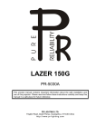
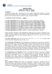
1
DESIGN 250
PR-1250
This product manual contains important information about the safe installation
and use of this projector. Please read and follow these instructions carefully
and keep this manual in a safe place for future reference.
PR LIGHTING LTD.
No. 571, Yingbin Road, Dashi Panyu, Guangzhou, 511430 China
http://www.pr-lighting.com
INDEX
SECTION
SAFE USAGE OF THE PROJECTOR
INSTALLING THE PROJECTOR
FITTING THE LAMP
POWER CONNECTIONS
CONTROL CONNECTIONS
DMX TERMINATOR
DMX CONTROL CHANNEL FUNCTIONS
TO SET THE DMX START ADDRESS
SETUP OPTIONS -PROJECTOR CONFIGURATION
LED INDICATION
STAND-ALONE MODE
MASTER/SLAVE MODE
OPERATION MENU
USER GUIDE
MAINTENANCE
KEEPING THE PROJECTOR CLEAN
TROUBLESHOOTINGS
TECHNICAL DATA
ELECTRICAL DIAGRAM
COMPONENT ORDER CODES
PAGE
3
4
4
5
5
6
7
8
8
9
9
9
10
19
20
20
20
22
23
24
Please note that as part of our ongoing commitment to continuous product development, specifications are
subject to change without notice. Whilst every care is taken in the preparation of this manual we reserve the
right to change specifications in the course of product improvement. The publishers cannot be held responsible
for the accuracy of the information herein, or any consequence arising from them.
Every unit is tested completely and packed properly by the manufacturer. Please make sure the packing and / or
the unit is in good condition before installation and use. Should there be any damage caused by transportation,
consult your dealer and do not use the unit. Any damage caused by improper use will not be assumed by the
manufacturer and / or dealer.
ACCESSORIES
THESE ITEMS ARE PACKED TOGETHER WITH THE PROJECTOR
Safety cord (1PCS)
Barndoors (1SET) (including 4 copper stand-offs, 4 screws and 4 flat washers)
This manual (1PCS)
INTRODUCTION
Thank you for purchasing the Design 250, PR-1250.
This product manual contains important information about the safe installation and use of
this projector. Please read and follow these instructions carefully and keep this manual in a
safe place for future reference.
The Design 250 is a projector of innovative, compact, silent colour changing, capable of
extraordinary performances in terms of colour mixing, reliability and versatility. The product
complies to CE norms and standards and uses international protocol DMX 512. The Design
250 is particularly suitable for television studios and theatres, stage lighting, limelights,
backdrops, inside or outside shops and shopping centres, sport centres and almost all
architectural applications.
The Design 250 features 6 kinds of colour filters for CYM colour mixing and 2 blades for
shutter/dimmer. The product has light level sensor track system which can adjust the status
of product automatically. And the projector can be setup easily via the touch-switches and
LCD display.
2/26
Design 250 EN.doc
SAFE USAGE OF THE PROJECTOR
When unpacking and before disposing of the carton check there is no transportation
damage before using the projector. Keep the carton well for future possible transportation.
Should there be any damage caused by transportation, consult your dealer and do not use
the projector.
The projector is suitable for indoor or outdoor use and is rated at IP65.
The projector is not designed or intended to be mounted on to inflammable surfaces.
The projector is only intended for installation, operation and maintenance by qualified
personnel.
The projector must be installed in a location with adequate ventilation, at least 50cm from
adjacent surfaces. Be sure that no ventilation slots are blocked.
Do not project the beam onto inflammable surfaces, minimum distance is 3m.
3m
Hot housing surface! Do not touch the housing of the projector with your hand during
operation.
Avoid direct exposure to the light from the lamp. The light is harmful to the eye.
Do not attempt to dismantle and/or modify the projector in any way.
Electrical connection must only be carried out by qualified personnel.
Before installation, ensure that the voltage and frequency of power supply match the power
requirements of the projector.
It is essential that each projector is correctly earthed and that electrical installation
conforms to all relevant standards.
Do not connect this device to any dimmer pack.
Make sure that the power-cord is never crimped or damaged by sharp edges. Never let the
power-cord come into contact with other cables. Only handle the power-cord by the plug.
Never pull out the plug by tugging the power-cord.
Keep the lamp clean. Do not touch the lamp with bare hands.
The projector should always be installed with a secondary safety fixing. A safety cord is
supplied for this, it should be attached as shown in “installing the projector” section.
The lamp used in this projector is a PHILIPS CDM-T 250W/830 discharge lamp. After being
switched off don’t attempt to restart the projector until lamp has cooled, this will require
approx 15 minutes. Switching the lamp on and off at short intervals will reduce the life of
both the lamp and the projector, but occasional breaks in operation will prolong the life of
the lamp and projector.
Never run the projector without a lamp.
There is no user serviceable parts inside the projector, do not open the housing and never
operate the projector with the covers removed.
Always disconnect from the mains, when the device is not in use or before
cleaning it or before attempting any maintenance work.
NOTE: PLEASE REMOVE THE SPONGE EFFECT LOCKING CYLINDER INSIDE THE
PROJECTOR BEFORE OPERATING!
(How to open the access cover please refer to “fitting the lamp” section)
3/26
Design 250 EN.doc
INSTALLING THE PROJECTOR
The unit was designed to make installation easy: it can be fitted on a floor, wall or ceiling as
required and will operate in any working position, as the head can be rotated through 90°.
Always ensure that the projector is firmly anchored to avoid vibration and slipping whilst
functioning. Always ensure that the structure to which you are attaching the projector is
secure and is able to support each Design 250. For safety the projector should have a
secondary fixing with a safety chain through the 2 secondary safety eyes on both sides of
the unit.
Note: For installing the barndoors, first install the 4 copper stand-offs in the unit head, and
then place the barndoors on the 4 copper stand-offs and fasten them with 4 screws and flat
washers.
FITTING THE LAMP
Loosen the 2 M6 screws and then open the head cover as shown in the figure above.
Reveal the lamp holder by gently moving the colour filters and blades aside from the center.
Plug the lamp into the lamp holder. Note: To avoid premature lamp failure, do not touch the
lamp glass with your fingers. If you touch the lamp during installation, clean it carefully with
rubbing alcohol and a clean, lint-free cloth before operation.
Close the cover and then tighten the 2 M6 screws.
NOTE: The CDM series are high pressure lamps with external igniters ( ). Care should
always be taken when handling these lamps. Always read the manufacturers "Instructions
for use" enclosed with the lamp.
4/26
Design 250 EN.doc
POWER CONNECTIONS
Use the power cord provided to connect the mains power to the projector. The user can
connect by yourself what you need. Open the underside of the base by undoing the 4
screws. You can see as shown in the figure above. To connect the power cord to the
relevant holder. To pay attention to the voltage and frequency marked on the panel of the
projector. It is recommended that each projector is supplied separately so that they may be
individually switched on and off.
IMPORTANT
It is essential that each projector is correctly earthed and that electrical installation
conforms to all relevant standards. Power consumption of the Design 250 is 350W at
220V.
CONTROL CONNECTIONS
Connection between controller and projector and between one projector and another must
be made with 2 core screened cable, with each core having at least a 0.5mm diameter.
Use the 2 XLR cords provided to connect the control to the projector. The user also
connects by yourself what you need. Open the underside of the base by undoing the 4
screws. You can see as shown in the figure above. To connect the XLR cord to the relevant
holder.
The Design 250 accepts digital control signals in standard DMX512 (1990) format.
Connect the controller’s output to the first fixture’s input, and connect the first fixture’s
output to the second fixture’s input. The rest may be deduced by analogy. Eventually
connect the last fixture’s output to a DMX terminator as shown in the figure below.
5/26
Design 250 EN.doc
DMX TERMINATOR
In the Controller mode, the DMX output has to be connected with a DMX terminator at the
last fixture in the chain. This prevents electrical noise from disturbing and corrupting the
DMX control signals.
The DMX terminator is simply an XLR connector with a 120Ω (ohm) resistor
connected across pins 2 and 3, which is then plugged into the output socket on the
last projector in the chain. The connections are illustrated below.
6/26
Design 250 EN.doc
DMX CONTROL CHANNEL FUNCTIONS
The Design 250 uses 7 DMX channels. They are listed in the following table.
CHANNAL
FUNCTION
DMX VALUE
1
Dimmer
000-255
From black to full open in linear
017-035
Colour1
036-054
Colour 2
055-073
Colour 3
074-092
Colour 4
093-110
Colour 5
111-128
Colour 6
129-255
Mix CYM colour from slow to fast
2
Colour Mixing
DESCRIPTION
3
Cyan
000-255
Cyan enters gradually
4
Yellow
000-255
Yellow enters gradually
5
Magenta
000-255
Magenta enters gradually
6
M-speed
000-255
Control motor speeds from fast to
slow
000-048
Reserved
049-080
Reset
081-112
Reserved
113-144
Lamp OFF after 10 seconds
145-223
Reserved
224-255
Lamp ON
7
Control
7/26
Design 250 EN.doc
SET THE DMX START ADDRESS
Each Design 250 must be given a DMX start address so that the correct projector responds
to the correct control signals. This DMX start address is the channel number from which the
projector starts to “listen” to the digital control information being sent out from the controller.
The Design 250 has 7 channels, so set the No.1 projector’s address 001, No.2 projector’s
address 008, No.3 projector’s address 015, No.4 projector’s address 022, and so on.
Launch the projector. Press button ENTER more than 5 seconds to unlock panel.
Press button ENTER, it will display address;
Press button UP and DOWN, you can set the address;
Press button ENTER to confirm; In the same time. The GREEN LED will flash one time. It means the
setting has been enabled.
Press button FUNC, it will return to the upper menu one by one.
SETUP OPTIONS - PROJECTOR CONFIGURATION
Projector configuration can be set conveniently via press button switch and LCD display. After the
projector is switched on, the projector will reset automatically and then the display will show
the DMX start address (if you have already set the DMX start address and saved it, the
screen will display the last setting).
Launch the projector. Press button ENTER more than 5 seconds to unlock panel.
Press button UP or DOWN if you want to browse through the various Setup Options. There are 11
option codes from DMX Address to Lamp Manual Control, and each code has a specific
function.
Press button ENTER to save your settings or enter the next menu. Press button UP or DOWN to shift
Press button FUNC, it will return to the upper menu one by one. The display will return automatically
to the function of address display if you stay for about 60 seconds defaulted.
8/26
Design 250 EN.doc
LED INDICATION
Green:
ON —— DMX signal OK or in the Master mode;
OFF —— No DMX signal;
Flash ——DMX error;
Blue:
ON —— Power ON;
OFF —— Power OFF;
Orange:
ON —— To set control panel;
OFF ——To stop set control panel ;
Red:
ON —— Master/Slave mode enabled or in the Slave mode;
OFF ——Master/Slave mode disabled;
STAND-ALONE MODE
Without using a controller, setup options Master mode enabled, the projector will run in
Stand-Alone mode with automatic programmes. See the section on “Setup Options –
Projector Configuration” for full details of the available combinations.
The DMX start address can be setted discretionarily.
MASTER/SLAVE MODE
Without using a controller, many projectors can run synchronously in the Master/Slave mode
by linking them with each other. Connect the master’s output to the first slave’s input, and
connect the first slave’s output to the second slave’s input. The rest may be deduced by
analogy. Eventually connect the last slave’s output to a DMX terminator. The example as
shown below:
Select one projector as the master with setting options Master mode enabled but slaves.
Regard the other projectors as the slaves setting options Slave mode enabled and all DMX
start address “001”.
If the projectors work normally, the LED should like this: Master—Green LED always on.
Slave—Red LED always on.
9/26
Design 250 EN.doc
OPERATION MENU
DMX Address
Reset
Operation
Mode
Option Setting
Information
Test Mode
Menu
User
Memories
Time Modes
Light Level
Sensor
Time Clock
Lamp Manual
10/26
Design 250 EN.doc
z
SUBMENU
¦ DMX Address
DMX Address
XXX(001~512)
¦ Reset
Are You Sure?
11/26
Design 250 EN.doc
¦ Operation Mode
Mode =
DMX Operation
Select Memory
Preset Memory 1
Select Memory
Preset Memory 2
Mode =
Master mode
Select Memory
Preset Memory 3
Select Memory
User Memory 1
Select Memory
User Memory 2
Select Memory
Preset Memory 1
Select Memory
Preset Memory 2
Mode =
Slave mode
Select Memory
Preset Memory 3
Select Memory
User Memory 1
Select Memory
User Memory 2
Slave Mode Type
Inc Step (DMX 1)
Slave Mode Type
Abs Step (DMX 2)
Slave Mode Type
Inc Step (DMX 1)
Slave Mode Type
Abs Step (DMX 2)
Slave Mode Type
Inc Step (DMX 1)
Slave Mode Type
Abs Step (DMX 2)
Slave Mode Type
Inc Step (DMX 1)
Slave Mode Type
Abs Step (DMX 2)
Slave Mode Type
Inc Step (DMX 1)
Slave Mode Type
Abs Step (DMX 2)
Mode =
Static Scene
12/26
Design 250 EN.doc
¦ Option Settings
Lamp Control By
Power On
Option
Lamp Control
Lamp Control By
Control Channel
Lamp Control By DMX
Present
Option
Display Mode
Display
On Always
Display
Off After Delay
Disp Dim Level Min
Disp Dim Level 1
Disp Dim Level 2
Disp Dim Level 3
Disp Dim Level 4
Option
Display Dimming
Disp Dim Level 5
Disp Dim Level l6
Disp Dim Level 7
Disp Dim Level 8
Disp Dim Level 9
Disp Dim Level Full
Option
Fixture Type
(WARNING:
Never change
the fixture type
or the system
will be
damaged!)
Option
Defaults
Fixture Type = Design
150
Fixture Type = Design
250
Fixture Type = Design
400
Fixture Type = Design
1000
Defaults
Off
Defaults
Restore Defaults
13/26
Design 250 EN.doc
¦ Information
Display
Lamp Hours
Display
Total Hours
Display
Temperature
Display
Firmware Version
Lamp Hours =XX
XX is the lamps elapsed
time(Press
DOWN&UP&ENTER button
to the next menu)
Total Hours = XX
XX is the project elapsed
time
Temperature
Display Board
Temperature
Driver Board
Temperature
Lamp Housing
Firmware Version
Display Board
Firmware Version
Driver Board
Reset Lamp Hours
Are You Sure?
Display Board =
XX
Driver Board = XX
Lamp Housing
Not Available
Display Board =
X..X.X
Driver Board =
X.X.X
¦ Test Modes
Factory Setup Off
Test Modes
Factory Setup
Factory Setup On
Self Test Off
Test Modes
Self Test
Self Test On
14/26
Design 250 EN.doc
¦ User Memories
Edit User Memory
User Memory1
User Memory 2
Static Scene
Scene XX
XX(1~32)
Dimmer
DimmerXXX
XXX(001~255)
Color
(Overrides CMY)
ColorXXX
XXX(001~255)
Cyan
CyanXXX
XXX(001~255)
Magenta
MagentaXXX
XXX(001~255
Yellow
Yellow
XXX(001~255)
M-Speed
M-SpeedXXX
XXX(001~255)
Delay
DelayXX
XX(0.25s~100min
Seconds)
Link To Step
Link To StepXXX
XXX(1~32)
Dimmer
Dimmer XXX
XXX(001~255)
Color
(Overrides CMY)
Color XXX
XXX(001~255)
Cyan
Cyan XXX
XXX(001~255)
Magenta
Magenta
XXX
XXX(001~255)
Yellow
Yellow XXX
XXX(001~255)
M-Speed
M-Speed XXX
XXX(001~255)
Delay
Delay XX
(0.25s~100min)
Seconds
Link To Step
Link To Step
XXX(1~32)
Scene XX
XX(1~32)
Dimmer
Dimmer XXX
XXX(001~255)
Color ( Overrides
CMY)
Color XXX
XXX(001~255)
Cyan
Cyan XXX
XXX(001~255)
Magenta
Magenta XXX
XXX(001~255)
15/26
Design 250 EN.doc
Yellow XXX
XXX(001~255)
Yellow
Reset User
Memory 1
Init User Memory
Reset User
Memory 2
Reset Static
Scene
Reset User 1 ?
<Unlock> 2 3 & 4
(Press
UP/DOWN/ENTER
button to set
option)
Reset User 2 ?
(Press
UP/DOWN/ENTER
button to set
option)
Reset Static Scn
(Press
UP/DOWN/ENTER
button to set
option)
16/26
Design 250 EN.doc
¦ Timer Modes
Timer Modes
On / Off
Timer Modes
Always On
Timer Modes
Use Start / Stop
Start 1 =
Power On
Set Start 1 to:
Power On
Start 1 =
XX
Set Start 1 to:
Start By Time
Start 1 =
Light Level
Set Start 1 to:
Light Level
Stop 1 =
Power Off
Set Start 1 to:
Power Off
Stop 1 =
XX
Set Stop 1 to:
Stop 1 By Time
Stop 1 =
Light Level
Set Stop 1 to:
Light Level
Start 2 =
Power On
Set Start 2 to:
Power On
Start 2 =
xx
Set Start 2 to:
Start By Time
Start 2 =
Light Level
Set Start 2 to:
Light Level
Stop 2 =
Power Off
Set Stop 2 to:
Power Off
Set Start 1 Time
Hour = XX
Set Start 1 Time
Minutes = XX
Set Stop 1 Time
Hour = XX
Set Stop 1 Time
Minutes =XX
Set Start 2 Time
Hour = XX
Set Start 2 Time
Minutes =XX
Set Stop 2 to:
Set Stop 2 Time
Set Stop 2 Time
Stop 2 By Time
Hour = XX
Minutes =XX
Stop 2 =
XX
Stop 2 =
Light Level
Set Stop 2 to:
Light Level
17/26
Design 250 EN.doc
¦ Light Level Sensor
Light Level
On Set Point
Light Level
Off Set Point
Display Current
Light Level
Set To Current
Light Level
Current On Level
Set to - XX
Set By Entering
Light Level
On Light Level =
XX
Set To Current
Light Level
Off Light Level
Set to - XX
Set By Entering
Off Light Level
Off Light Level = XX
Current Light
Level = XX
¦ Time Clock
Get Current Time
Current Time = XX
Set Time
Set Time
Hour = XX
Set Time
Minutes =XX
Current Time =
XX:XX
**The time is 24 hours;
¦ Lamp Manual Control
Lamp Status
Status =
XX
Control = XX
Turn Lamp On
Turn Lamp Off
** The parameter of the lamp status which only used in factory test.
18/26
Design 250 EN.doc
USER GUIDE
z
How to use Timer Modes to control the projector?
If the user needs to switch on the projector at 20:00, and switch off at 23:00. The process
provided in the following figure.
z
ENTER
Timer Modes
Start 1=20:00
Set Start 1 to:
Start By Time
Set Start 1
Time Hour=20
ENTER
Timer Modes
Stop 1=23:00
Set Stop 1 to:
Start By Time
Set Stop 1
Time Hour=23
How to use Light Level Sensor?
If the user needs to switch on the projector as soon as the Light Level reaches at level 10, and
switch off at level 20. The process provided in the following figure.
ENTER
Light Level
Sensor
Light Level On
Set Point
Set By Entering
Light Lever
ENTER
Light Level
Sensor
Light Level On
Set Point
Set By
Entering Light
Level
19/26
On Light
Lever=10
On Light
Level=20
Design 250 EN.doc
MAINTENANCE
If the projector’s lens becomes damaged or broken it should be replaced. If the lamp
becomes damaged or deformed in any way it must be replaced. If the light from the lamp
appears dim this would normally indicate that it is reaching the end of its life and it should
be changed at once, old lamps run to the extremity of their life can explode. If the projector
does not function, check the power fuse inside the projector, it should only be replaced by
fuse with the same specified value. When changing the fuses, please undo the 4 M6
screws on the base of the projector and then open the base cover. Should these be
damaged call a qualified technician before replacement. The projector has a thermal
protection device that will switch off the projector in case of overheating.
Any maintenance work should only be carried out by qualified
technicians.
KEEPING THE PROJECTOR CLEAN
To ensure the reliability of the projector it should be kept clean. The lens and dichotic
colour filters should also be regularly cleaned to maintain an optimum light output. Do
NOT use any type of solvent on dichotic colour filters.
Cleaning frequency depends on the environment in which the fixture operates: damp, smoke
or particularly dirty surroundings can cause greater accumulation of dirt on the unit’s optics.
A soft cloth and typical glass cleaning products should be used in cleaning. It is
recommended to clean the external optics at least once every 20 days and clean the
internal optics at least once every 30 / 60 days.
Do not use any organic solvent, e.g. alcohol, to clean the reflector,
colour filters or housing of the apparatus.
TROUBLESHOOTING
PROBLEM
The projector
switch on
doesn’t
The lamp comes on but
the projector doesn’t
respond to the controller
The beam appears dim
POSSIBLE CAUSE
-The power supply is not
present
-The lamp is not working
-Wrong DMX configuration
and/or start address
- Defective DMX cable
-Dust or grease
contamination on the
optics.
-The lamp is at the end of
its life
20/26
ACTION
Check the fuse on the power
socket.
Replace the lamp.
Make sure that the projector is
correctly configured.
Replace or repair the DMX cable.
Check the optics are clean.
Replace with a new lamp of the
specified type and rating.
Design 250 EN.doc
LIGHT OUTPUT
21/26
Design 250 EN.doc
TECHNICAL DATA
VOLTAGES:
100/120/200/220/230/240V AC, 50Hz or 60Hz
POWER CONSUMPTION:
350W @ 220V
LAMP:
Type : PHILIPS CDM-T 250W/830
Colour Temperature: 3000ºK
Socket: G12
Manufacturers Rated Lamp Life: 9000 Hours
COLOURS:
CYM colour mixing
With crossfade effect at various speeds
CHANNAL:
CONTROL:
DMX512: 7 Channels
DMX512
Stand-Alone Automatic mode
Master/slave mode
Static Scene
PRESET MEMORY:
3 preset memories
PROGRAM SYSTEM:
2 user memories
BEAM ANGLE:
42º
HEAD MOVEMENT:
6º-90º (manual adjustment)
OTHER FUNCTIONS: Light Level Sensor
Timer mode
Remote reset
Lamp control
WATERPROOF:
IP65
HOUSING:
Cast aluminium with paint finish (IP65)
WEIGHT:
20.6Kg
22/26
Design 250 EN.doc
ELECTRICAL DIAGRAM
23/26
Design 250 EN.doc
COMPONENT ORDER CODES
NAME
TRANSFORMER
THERMOSTAT
CAPACITOR
BALLAST
IGNITOR
RELAY
FAN
FUSE
LAMP
COVER GLASS
CYAN MOTOR
YELLOW MOTOR
MAGENTA MOTOR
SHUTTER MOTOR
CYAN AND HOLDER
YELLOW AND HOLDER
MAGENTA AND HOLDER
LAMP CONTROL PCB
RECTIFICATION PCB
SIGNAL PCB
DISPLAY PCB
MOTOR DRIVE PCB
PART NO.
NUMBER
040030038
190010054
140010042
040070023
040090016
192010026
030069010
270041020
100050060
080090021
030040078
030040078
030040077
030040077
016330054
090100040
016330053
090100041
016330053
090100042
230020167
230020168
230020169
230020171
230020172
1
1
1
1
1
1
1
1
1
1
2
2
2
2
1
1
1
1
1
1
1
1
1
1
1
REMARK
100~245V 50/60Hz
95°C/10A/250V
32µF AC 370V
250W 3.0A
230V/50-60Hz 4~5KV
3E-230B-W
6.3A 5*20
CDM-T 250W
17HS0001-06KL
17HS0001-06KL
17HS0001-05KL
17HS0001-05KL
HOLDER
5*25*11.3
5*25*11.3
5*12*11.3
5*12*11.3
DICHROIC COLOUR FILTER
HOLDER
DICHROIC COLOUR FILTER
HOLDER
DICHROIC COLOUR FILTER
NOTE: You may order all parts of the Design 250 besides the table listed above. When
ordering please state the exact name and part no.. Repairs must be carried out by a
qualified technician.
24/26
Design 250 EN.doc
25/26
Design 250 EN.doc
PR LIGHTING LTD.
No. 571, Yingbin Road, Dashi, Panyu, Guangzhou, China
Post-Code: 511430
TEL: +86-20-8478 1888
FAX: +86-20-8478 6023
P/N: 321010082
Last Revision: 17:10:2005
26/26
Design 250 EN.doc