1
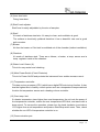
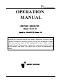
OPERATION
MANUAL
LOW TEMP. INCUBATOR
(Model : ILP-01,11)
Manual No : 00HAA0001170 (Version : 5.0)
This operation manual describes the important subjects to maintain
the product’s functions and to use it safely. Especially, be sure to read
<Safety Precaution> carefully before you use this equipment. Please
keep this manual close to the equipment to use it after reading
through it once. Please place it where the new user can find it easily
for the safety use when you hand over or lend the equipment to
others.
Page
1
Thank you for purchasing Jeio Tech’s product. This operation
manual forms a definition of warning marks according to the level of
importance and danger in order to use the product safely and
correctly and prevent the users from accidents or injuries. Hence,
please use the product in accordance with the instructions.
Safety Notice
1. Caution
This product can cause a big accident in case of improper use of inflammable
and combustible solvents in the chamber. Also, operation in the high
temperature might cause a mechanical trouble and quality deterioration due to
the function and the characteristic of the product.
Safety Precautions
“Danger” means that the user may have
serious
damage
and
even
die
by
improper handling on this unit.
“Warning” means that the user may
have
serious
damage
by
improper
handling on this unit.
“Caution” means that the user may have
minor damage and unit may have
physical damage by improper handling
Page 2
Although Jeio Tech thoroughly investigates the possibilities of
dangerous situations from using the product, it is not possible to know
every single danger. Hence, precautions described in this manual do
not cover all the dangerous conditions.
However, you can operate this product safer when you follow the
directions in this manual. Please, be sure to pay attention to the
directions and be cautious so that a mechanical trouble or an accident
would not be occurred.
2. Warning mark of product
The most important thing of the warning is a warning label attached to the
product. It is located in front of the door.
Be fully aware of the warning contents during operation.
※ Please change to the new warning label when it is unreadable from wearing out. Please
request the new label to us.
Copyright 2004 Jeiotech.co.Ltd. ALL RIGHT RESERVED.
Page
3
Contents
1. For Safe operation
………………....................................................
2. Application and Features
3. Installation
5
…………..................................................
5
…………….....................................................................
7
4. Precautions ....................................................................................
12
5. Name of the each part ……….........................................................
13
6. Operating Controller
17
…...…….......................................................
7. Maintenance and Cleaning
……..………........................................
8. Dealing with Abnormal Condition
9. Warranty
……............................................
28
………………..................................................................
30
10. Disuse Products
11. Specifications
…………............................................................
30
……………............................................................
31
12. Install Lab Program
13. How to use Lab Tracer
Page 4
27
…………………...........................................
32
………………….......................................
34
1. For Safe Operation
Be fully aware of the safety since this product does not have a hydrostat.
Do not put inflammable substances like organic solvents.
In case of operation for the high temperature, the samples might ignite and explode
from vaporization in the chamber. Explosive materials are acetic acid ester, nitro
compound, and etc. Inflammable materials are inorganic peroxides, acetates,
organic solvents, and etc. This equipment does not have a hydrostat.
2. Application and Features
1) Purpose
(1) Low temperature incubator is suitable for preservation of culture ground,
culture-fluid, and seeds (0℃ ~ 4℃), degeneration test of grain and meat
(10℃ ~ 14℃), cultivation of microbes and plants, COD/BOD measurement
(20℃ ~ 25℃), suspension of enzyme reaction, preservation of enzyme
solution, and desalting of enzyme extract.
(2) It also can be used for high temperature tests (55℃ ~ 60℃) such as
environmental variation tests of cultivation, grease, and pigment of high
temperature microbes and bacteria.
Do not rebuild the equipment.
Do not use it for other purposes.
An electric shock or a mechanical trouble might be occurred from rebuilding or using it
for other purposes.
2) Characteristics
(1) This equipment is a multi-purpose low temperature incubator for
biotechnology, pharmacy, medical science, chemistry, and biology. It has
applied CSL (Custom Logical Safe) – Control System that Jeio Tech
originally developed for the convenience in use and the safety.
(2) CLS – Control System means “Control system which has a logical safety
device specialized for an individual model.” Laboratory must have a thermal
Page
5
safety because there are a lot of inflammable reagents. This system is the
highest safety control device (patent applied) and makes the equipment
suitable for this kind of environment.
(3) The unit can be connected to PC using the attached communication port. It
is also possible to monitor and set the values using the Lab Tracer (CD
included).
(4) The unit is designed to stop the heater and blower in order to protect the
user from heat when the door is opened during the operation.
(5) The unit has insulation for high temperature in the outside of the inner
chamber and inside of the door and also has a chamber silicone door for
high temperature. Therefore, insulation is perfect, and the level of losing
heat is very low.
(6) The inner glass door is good for insulation and observation.
(7) The door attached a magnetic packing has effects on impact relief and
double secrecy.
(8) Circulated fan of a cross type is attached for the distribution of uniform
temperature and creates an indirect air-circulation.
(9) Safety circuit has built-in to protect the equipment from an excess current
and an overheating.
(10) Development of exclusive controller allows the user to control the speed (3
steps) of the inner fan and defrosting (period and time). 9-Step
Programmed Control allows the user to set and operate 9 different
temperature and time (max: 99 hours 59 minutes). Operation is possible to
be repeated from once to 999 rounds.
(11) -Program Operation-
Page 6
3. Installation
(1) Notice while installation.
1) Please check the following contents after opening the package.
Main body (1 set), Shelf(1 ea), Shelf maintenance clip(4ea), Operation manual
(1ea) Com. CD (1 ea) Com. Cable – (1ea) Power Cord – (1ea)
2) Be careful not to get the item shocked while transportation.
This item should be protected from outer shock.
3) This unit will work correctly on a proper power supply. Please check whether the
power supply and ID Plate information are the same. User must use the power
supply connected to earth, and power cord must be connected to wall outlet
supplying ground point.
Connect the power properly with correct voltage, phase,
and capacity.
Improper connection causes a fire or an electric shock.
Use the grounded power supply.
Ungrounded power can give a serious damage to the
equipment and the user. For the safety, do not connect a grounding conductor to
the gas and water pipes.
4) Outlet should be located near the unit and shall be easily accessible.
Do not use an ejected socket or a double tap.
Cable damages or a fire can occur by an excess current.
5) Please install the unit in the flat place where prevents vibration and shock.
6) Please avoid heat sources and direct sun light, and locate the unit where
ambient temperature range is 5°C ~ 40°C and relative humidity is lower than
80%.
7) Please do not let moisture, organic solvents, dust, and corrosive gas enter into
the control box.
8) Please don’t install the unit in the dangerous place where there are flammable
gases, explosive materials, and organic solvents such as acetone and
Page
7
methylene chloride.
9) Please secure enough space for installation because the door opens 180° to the
left.
10) Please do not install the unit near by the machines generating a strong high
frequency noise.
(2) How to fill water into water tank
ILP-01
(1) Remove the screws on the rear fan filter by a screw driver when it’s
off-operation, take out the same from the unit, fill water by using a funnel.
(2) Remove the stopper of a funnel, fill water into the water tank while checking the
water level through the water level viewer.
Preferable distilled water preventing from occurring corrosion for the
extension of the expected life span of the product. (water tank 3.4ℓ in full
capacity, and its alarm starts to buzz when its water level is lower than the
1.4ℓ, and stopped the operation at the same
time. Ensure that water tank should be filled in full capacity at the original
installation in order to fully load the water inside of the hose and radiator.
Page 8
(3) Put the stopper on a funnel when water tank fully filled.
Put the main switch on, select the required temperature, start the operation
for a minute. (Do not touch the unit with wet hands preventing from a risk of
electric shock)
(4) Fill water again into the water tank in case its water level is lower than the
indicating point When it’s off-operation. After finishing the filling water, put
the stopper on a funnel,
Re-install a fan filter on the unit.
(5) Check if it’s on normal operation without any trouble when it’s switching on
ILP-11
(1) Pull out the water supplement door in the rear position of the unit when it’s
off-operation
Try to pull it out over certain strength because it’s fixed with magnetic
attraction.
(2) Remove the stopper of a funnel, fill water into the water tank while checking
the water level through the water level viewer.
Preferable distilled water preventing from occurring corrosion for the
extension of the expected life span of the product. (water tank 3.4ℓ in full
capacity, and its alarm start to buzz when its water level is lower than the 1.4ℓ,
Page
9
and stopped the operation at the same time. Ensure that water tank should be
filled in full capacity in the original installation in order to fully load the water
hose and radiator.
(3) Put the stopper of a funnel when water tank fully filled.
Put the main switch on, select the required temperature, start the operation for
a minute. (Do not touch the unit with wet hands preventing from a risk of
electric shock)
(4) Fill water again into the water tank in case its water level is lower than the
indicating point When it’s off-operation. After finishing the filling water, put the
stopper on a funnel,
Re-install a fan filter on the unit.
(5) Check if it’s on normal operation without any trouble when it’s switching on
Page 10
3) How to fixate the shelf.
(1) check which is the upper-end, and lower-end of the shelf supporter.
(2) Insert the upper-end of the shelf supporter into the hole inside of the chamber,
and next insert the lower-end of the same into the hole at one step down by
bending the whole shelf
supporter. (be cautious of bending the shelf supporter not to injury your
finger.)
(3) After finishing the fixation of 4 ea shelf supporters at the same height, put the
shelf on the shelf supporter.
Make sure that its horizontal level is correct, and re-fixate the shelf supporter if
it’s not correct.
Page 11
4. Precaution
(1) Please do not touch the power cord and electric parts with wet hands.
(2) Please do not put explosive and flammable chemicals (Alcohol, Benzene, and
etc) into the incubator.
(3) The samples inside of the unit are very hot when the unit operates and for a
while after it stops. Please put on safety gloves when you touch samples.
(4) Please do not place flammable materials near by the unit.
(5) Please do not pour water on the unit directly when you clean it.
(6) Please do not put conductive and flammable materials through ventilation or
power supply port. It is dangerous and might cause fire and electric shock.
(7) Circuit and electric components used in this unit are developed by Jeiotech.
Please do not try to repair by yourself. Incorrect combination of electric parts
may cause a fire. You must ask an official Jeiotech dealer or a distributor in your
region.
Do not put explosive and flammable materials inside
of the chamber.
Page 12
5. Name of the each part
ILP-01
Page 13
ILP-11
(1) Door
For using adiabatic material, we removed dewdrops on the surface of the door.
(2) Inner Door
User can observe the inside of the chamber through this transparent and made of
reinforced glass inner door.
(3) Magnetic packing
It absorbs the impact and protects the samples doubly when door opens and
closes.
Page 14
(4) Inner door latch
Fixing Inner door.
(5) Shelf Level adjuster
Shelf level is easily adjustable by the size of samples
(6) Shelf
It’s made of stainless steel wire. It’s easy to clean, and ventilation is good.
The surface is electrically polished therefore it has a beautiful view and a good
anti-corrosion.
(7) Blower
Air from the heater or Cold sink is ventilated out of the chamber (Indirect ventilation)
(8) Chamber
It’s made of stainless steel. There are a blower, a heater, a temp. sensor and a
temp. regulator inside of the chamber.
(9) Water Level Viewer (A)
This is for easy water level checking
(10) Main Power Switch (Circuit Protector)
This is for Power On/Off and protects the instrument from sudden excess current.
(11) Temperature controller
This has a micro processor (CPU) which has a digital PID auto tuning function. It also
has the highest level of safety control system such as a temperature compensational
function for temperature sensor and a heating volume controller.
(12) Over temp. limit
If a heater temperature rises higher than a set temperature, the unit cuts the power of
the temperature controller, makes the over temperature LED blink, and warns with a
beep sound. To resume the operation, please turn the knob clockwise to set about
15% higher than a set temperature and press a Start/Stop switch ones. Then, check
whether the run LED of temperature controller is on.
(13) Communication port
Page 15
User can monitor and control this unit by PC. Data print out through PC printer is also
available. The unit can be connected to PC’s com1 and com2 port through a
RS-232C protocol cable.
(14) Door Handle
This is for opening and closing the door.
(15) Radiator cooling fan
This is a fan for cooling the Radiator
(16) Water Level Viewer (B)
This is for checking Water level in the tank and water supply.
(17) Filter
This is for filtering dust from the water supplied into the radiator. The filter can be
attached and detached easily for cleaning. Detach the filter when supplying water in
the tank(ILP-01 only)
(18) Main Power Code
This is for connecting power code to rating voltage
(19) Water Supplement Door
Water supplying hole can be seen when opening the door which is fixed by magnetic
(ILP-11 only)
Page 16
6. Operating Controller
1) Characteristics
(1) CLS-Control System carries out temperature control of equipment and heating
control in the Main CPU where precise PID algorithm is possible. All actions for
safety are conducted by a selective functional Logic IC which is installed
separately. This is designed to conduct safety performance against any electric
and electronic shock on the unit.
(2) CLS-Control System shuts down all 2 phase power supply to each part
immediately and informs user instability by audible and visual device, and then it
keeps in safety mode until all instability conditions are removed.
(3) CLS-Control System has wait on/off timer function for the user’s convenience.
The function starts or stops the operation after the set time.
(4) CLS-Control System gives user two choices when the unit’s operation is
terminated by a power failure and then the power recovers. One is a resume of
the unit’s operation. Another one is to keep the unit in standstill.
(5) CLS-Control System is composed that feeble electric current streams down to
only 5V, 10mA at a point of contact of a used safety device. There is no damage
of a point of contact in use of a long time. So, the durability is very long. After it
stops the control of the Thyristor which controls electric current stream of the
heater that uses a large electric current when a safety device is operated, it
shuts down the power through Magnet Switch’s disconnection of a point of
contact. It prevents the point of contact from damaging and a noise revelation of
a power switch. It enforced with the mentioned objection order above when an
operation of equipment starts, and it also prevents the point of contact from
damaging and a noise revelation of Magnet Switch.
2) Name and Operation
Page 17
Main CPU of this unit has certified S/W which allows Digital PID-Auto tuning. The unit
has a temperature deviation/correction function for the Pt-100Ω sensor and the
highest safety level of control system.
(1) Auto Tune LED
It blinks during auto-tuning.
(2) Wait On Timer LED
This LED shows when the unit is on a timed ‘on’ function. The LED blinks when the timer is
activated, and it is completely turned on when the timer is on stand by.
(3) Heater LED
It shows whether heating function is on.
(4) Wait Off Timer LED
This LED shows when the unit is on a timed ‘off’ function. The LED blinks when
the timer is activated and is completely turned on when the timer is on stand by.
(5) Over Temp. limit LED
If the heater temperature rises higher than set temperature, it cuts the power of
the temperature controller, makes the over temperature LED blink, and an
alarming beep rings. To resume the operation, please turn the knob about 15%
higher than a set temperature and press a Start/Stop switch once. Then, check
whether the run led of temperature is on.
(6) Temp. Button
This button is for temperature setting.
(7) Timer Button
This button is for timer setting.
(8) Up Button
This button is for increasing the set value.
(9) Down Button
This button is for decreasing the set value.
(10) Enter Button
This button is for saving value after changing the set value.
(11) Lock Button
Page 18
This button is for setting and releasing the lock function and using pattern function in the
Lab Tracer. Press a lock button for a while (about 1 second), then lock function is set with
a beep sound. Press a lock button for a while (about 1 second) again, then lock function
is released with a beep sound. When a lock function is activated, the unit operates only
with a start icon after setting the pattern in the Lab Tracer.
(12) Auto Tune Button
The auto tune begins if you press this button for 1 second.
(13) Start/Stop Button
This button is for start/stop of unit and for resuming operation after removing some
unstable factors when operation is terminated.
(14) Run LED
This LED indicates Work/Stop state of unit.
It turns on when the unit runs and turns off when the unit stops.
(15) PRO LED
This LED indicates whether the operation is in program or normal status. The
LED blinks when the operation is in program status, and it turned off when the
operation is in normal status.
(16) SV Display
This display is for showing set temperatures and remaining time when the timer function
is activated.
(17) PV Display
This display is for showing present temperatures.
(12)Temperature Setting Method
① Press
button. A set temperature value (SV) blinks. This means you can
change the set value.
② Press
button to change the digit number and then press
button when you save the value.
③ It goes back to the previous state without saving if you don’t touch any button
for 10 seconds.
Page 19
④ Press
button again when SV display blinks, then following additional
functions will be activated.
(13)Additional Function of
Button
① This is saving and loading function of set
temperatures.
Setting is as follows:
Press
and press
button to change the temperature
button to save.
Set temperature is saved in the memory and a
current set temperature is changed. Sv 2, Sv 3 can
be set using the same method.
Sv1, Sv2, Sv3 are
shown in order when you press
button
repeatedly. If you press it one more time, it becomes
the function to change a unit of a temperature.
② This is a function to change the unit of
temperature value. Initial display is ℃ and it can
be varied ℃ and ℉ by pressing
Page 20
Button.
Press
button again to move on to the next
function.
③ By buttoning
6 times, next function is
displayed.
This is a function of calibrating temp. errors.
Corrected value is displayed on PV display.
Next function is by buttoning
and
.
Pv is displayed on the SV display and the PV can
be set as the same PV of thermometer.
Set values by buttoning
by buttoning
and
, and store
..
You can see “AJST” on the left-handed display and see “SV” on the right-handed
display which is displaying “present value” for temperature.
This is to adjust the value which is corrected by a accurate thermometer.
Using
button, finish the process after all setting.
(14)Timer Setting Method
① Press
button.
Timer (On Timer / Off Timer) is shown on PV and time is shown on SV.
Set the time by pressing
button and save and finish by pressing
button.
② After the setting is done, a beep sound and W/ON LED inform that setting has been
completed.
Page 21
③ Press
button one more time. You can set the wait off timer. Set the time by
pressing
button and save and finish by pressing
button.
④ After the setting is done, a beep sound and W/OFF LED inform that setting has
been completed.
⑤ The function of Timer is shown below.
Temperature
Time
Wait on Timer
Page 22
Wait off Timer
· Wait On Timer
The unit begins to work after the time programmed on Wait On Timer passes.
The maximum of adjustable value is 99 hrs 59 min, and the minimum is 1min.
· Wait Off Timer
The unit stops after the time programmed on Wait Off Timer passes since SV and
PV meet.
· Combination of Wait On Timer & Wait Off Timer.
The unit works as a picture above.
⑥ Timer set deactivation
Press
button in order to deactivate timer function (Both on/off timer). In order
to cancel only one of the timers, set the value of the timer to 0.
(15)Additional Function of
When you press
Button (Auto Run)
button three times from the initial state, following function
operates.
① This is to select the machine mode in case of a power failure. This function operates
the equipment automatically after a power recovery in case of a block out during
operation or a power cut by mistakes. When the user sets to ‘Yes’, the equipment
operates the moment the power is recovered.
(16)Additional Function of
When you press
Button (Fan speed control)
button four times from the initial state, following function
operates.
Page 23
① This function is to control the speed of inner circulating fan. It is recommended to be
set as a third stage since slow speed does not contribute the temperature distribution.
(0 to 3 stage is possible.)
(17)Additional Function of
Button (Programmed Control)
9-Step Programmed Control allows the user to set and operate 9 different
temperature and time (max: 99 hours 59 minutes). Operation is possible to be
repeated from once to 200 rounds. When you press
button five times from the
initial state, following function operates.
① It indicates the entire repetitive number of program. Loop 100 means that it will
operate 100 times. Set the number by pressing
pressing
button and save by
button.
The next function operates when you input more than 1. Input 0 when you do not
want to operate this program.
② SEg.L is a segment logic that divides the section’s boundary. When you input 3
here, third program is repeated from second repetition. Set the section by pressing
button and save by pressing
button.
③ This function is to set the maintaining time of the first program. When you input
10:10, operation maintains for 10 hours and 10 minutes (max: 99 hours 59
minutes). Set the time by pressing
Page 24
button and save by pressing
button.
④ This function is to set the maintaining temperature of the first program (4℃ ~ 60℃).
Set the temperature by pressing
button and save by pressing
button.
⑤ You can set the 9 step program by operating ④ ~ ⑤. That is, you can set time 2
and temperature 2 at program 2 and set the time 3 and temperature 3 at program3 and
so on (till program 9). You can input 0 to cancel the setting.
(18)Auto Tuning
Perform Auto Tuning in order to get precise and rapid temperature control. PID value is
saved automatically after Auto Tuning.
If temperature control seems to weak, or there is a full of specimen inside the chamber,
Carry out Auto Tune at temperature that has frequently being used.
① Set the desired temperature.
② Press
button for a while (1 second), then Auto Tune display is shown (see a
picture above) and A/T LED is turned on.
Page 25
③ When you press
button, Run LED is turned on, A/T LED blinks, and Auto
Tune displays.
④ Auto Tune time varies depending on the ambient environment. When auto
tuning is done, the light on LED goes off, and the unit operates with the set
temperature. When you press
button for 1 second during operation,
auto tune display is shown and is set.
Please, do not put the specimen inside of the unit
when the Auto Tune is on operation.
(19)Lock Function
① This button is for setting and releasing the lock function and using pattern function in the
Lab Tracer. When you press
button for approximately 3 seconds, display shows
con.P with a beep sound. When a lock function is activated, the unit operates only with a
start icon after setting the pattern in the Lab Tracer.
Page 26
7. Maintenance and Cleaning
Pull out a power plug from the outlet before the
cleaning and inspection.
Turn off the main power switch and pull out the power plug
before the cleaning and inspection. An electronic shock or
damages on the unit might occur.
(1) When you clean the unit, pull out the power cord from the outlet and wipe it with a
soft and dry cloth. Wipe the dirt with a cloth containing the solvents that have a low
boiling point (methanol and ethanol).
(2) Do not use acid solvents, benzene, sharp materials, soapy water, washing solvents,
and hot water. They can cause the damage or discoloration of the unit. Parts with
rubber and plastic can be changed, degenerated, or discolored. Wipe the unit with
a dry cloth after using a natural detergent. Then, dry it completely.
Use proper methods and materials for cleaning and
inspection.
Do not pour the water directly or use polishing powder,
kerosene, acid on the unit. An electronic shock or
damages on the unit might occur.
(3) Use appropriate safety gloves for harmful chemicals and a safety mask for harmful
gasses in the event of cleaning accidental chemical spills from the unit.
(4) Do not pour the water directly on the equipment (especially control panel).
Short-circuit can be occurred.
(5) If the user tries to clean this unit with other method not mentioned on this manual,
please contact us in order not to damage the unit.
(6) Only authorized technician can treat the electronic parts inside of the equipment.
(7) Use only the original parts for replacing.
Do not disassemble the equipment.
An electronic shock or an injury might occur when you
disassemble since there are parts where high voltage
flows and high temperature locates inside of the
equipment.
Page 27
8. Dealing with abnormal condition
If the unit does not work.
Use the following procedure:
(1) check if use on proper voltage or current.
(2) check if RUN LED is lighting up.
If it’s turned off, press Start/Stop for restart.
(3) Check if the power supplied.
★ actions
symptom
Causes
Actions
Even when the unit is turned
An electric leakage, or a
If the problem persists, remove the
on, it turns off immediately.
Short-circuit.
power source, contact your local
dealer.
Even when the unit is turned
It is likely that power cord is
Turn Power switch on, fully plug in
on, the display does not
not fully connected or plugged
power consent.
appear on the panel.
out.
Power switch broken
Stop
Temperature controller broken
contact your local dealer.
The temperature can not be
Check whether RUN LED is
If Run LED is turning off, press
increased or decreased.
on or off.
Start/Stop.
The temperature can not be
“Err.S” message displayed
Stop
controlled.
on the PV panel.
contact your local dealer.
“Err.S”
message
not
the
the
operation
operation
immediately,
immediately,
Perform Auto Tune
displayed on the PV panel.
In case operation stopped by
the Over temp. limit
Check the followings
1) if O/T LED is turning
on in red.
1) Rotate the red knob of the Over
temp.
limit
clockwise
to
the
position which is greater 15% than
2) if there is beep sound
that of PV (present value).
constantly.
Press Start/Stop once more, red
light of O/T LED and beep sound
will disappear simultaneously.
2) Press Start/Stop once more, the
unit will restart with RUN LED and
Heater LED lighting up.
Page 28
symptom
Causes
Actions
The unit does not operate with
Check if the water level in tank
Fill the tank with water according to
beep sound constantly.
is in low position.
the manual instruction on water
supplement.
When
“Err.S”
message
Stop
the
operation
immediately,
displayed on the PV panel.
contact your local dealer.
Without any signal as not
A strong high frequency noise
Move or relocate the equipment in
described above, or touching
affected in the power supply.
question.
the keyboard, all the system
Check
if
high
frequency
has been broken down.
welder,
or
high
frequency
sawing
machine,
massive
SCR controllers have been
installed in the vicinity of the
unit.
Decreasing
time
temperature top long
for
Check
if
use
on
proper
Use on correct voltage for the best
voltage.
performance and life of the unit.
In case full of dust in the filter.
Take out the filter and clean it.
Check
Stop
if
water
pump
is
pumping.
the
operation
immediately,
contact your local dealer.
Check if rear radiator fan is
rotating.
Check if the circulation fan in
the chamber is rotating.
Please turn the power switch off immediately if the unit
does not function properly.
Do not attempt to disassemble the unit by yourself because replacement
and adjustment of parts require advanced skill and specialized equipment,
Please contact Jeio Tech, or your local dealer in the event of request for
repairs.
Handling the electric parts for the unit should be serviced only by the qualified persons.
Replacement parts should be sourced only by on standard specification.
Damage caused by an abnormal operation can not be covered with the Warranty.
Page 29
9. Warranty
(1) General
The product is warranted to be free from defects in material and workmanship
under normal use and maintenance for a period of 1 year on all components.
The warranty period begins on the date of original installation to the original owner.
For the fast and correct repair times, please provide complete details of any
problem encountered as the followings:
- Original dated proof of purchase.
- Serial number on the name plate of the product.
- Detailed description of the defective. (Position, symptom, etc…)
- Operating environment of the product.
(2) Conditions of the warranty
The limited warranty shall not apply to damage or defect resulting from:
- User’s misuse of the product, or negligent use.
- not properly installed, stored and cared by user.
- Abuse, improper use, modification, change, or alteration of the product.
- Damage as a result of floods, winds, fires, lightning, accidents, abnormal voltage
conditions, or other conditions beyond the control of the company.
- the operation beyond rated capacity, operation of electrical components at
voltages other than specified in the rating plate, or lack of proper maintenance or
service in accordance with User’s information manual.
10. Disuse product
In the event of disusing the product, or part, you should comply with the designated
method by the company as follows;
Disuse method for the main parts of the product.
Description
Model
T/W (Kg)
Outer Dimension(mm)
ILP-01
24.4
400 X 535 X 385
ILP-11
45
430 X 700 X 620
body
Page 30
Disuse method
Consult with the qualified
Person who can handle
industrial waste.
11. Specification
Model
ILP-01
ILP-11
Chamber volume
14L
48L
Temperature 5℃ to 40℃
Permissible
environmental condition
Temperature
Altitude up to 2,000m
Range
+3℃ ~ 60℃ at room temperature 20℃
Accuracy※
±0.1℃ at 20℃
Uniformity※
±0.5℃ at 20℃
Controller
Digital PID auto tuning
Sensor type
Timer
Pt 100 Ω
Pt 100 Ω
Wait on time, Wait off time
(Max. 99hr 59min, Min. 1min)
Internal
Stainless steel, 0.6t
External
Steel, 0.8t, powder coating
Shelves
Stainless steel wire, electro polished
Refrigerator
Material
Maximum relative humidity 80%
Heater
Thermoelectric element
Thermoelectric element
48W X 2
48W X 4
Cartridge Fin type 150W
Cartridge Fin type 300W
Over temp. limit
Hydraulic over temp. limit
Insulation
Nonflammable EPDM 19t
Inner door
Tempered safety glass, 5t
Safety device
CLS(Custom Logical Safe)-control system, ClassⅡ
Printer interface
RS232
Internal
315 × 200 × 230 ㎜
334 × 334 × 430 ㎜
External
400 × 535 × 385 ㎜
430 × 700 × 620㎜
Inner door
5t × 330 × 248 ㎜
5t × 337 × 433㎜
Electric requirements
AC 230 V, 50/60 Hz
AC 230 V, 50/60 Hz
Power consumption
1.2A
2.3 A
Weight(net)
24.4kg
45kg
Size
(W×D×H)
Page 31
12. Install Lab Tracer
1. Insert an installation CD, and then the software starts installation
automatically.
(In case of no automatic running, run “SETUP.exe” file in CD.)
2. Click “Next” button to choose destination of installation. (Default folder
recommended)
Page 32
3. Click “Install” to start installation.
4. Lab Tracer icon will be created on the desktop after successful installation.
5. To start Lab Tracer, double click the icon.
Standard
Recommend
Beyond Microsoft Windows 98
Microsoft Windows 2000, XP
CPU : Beyond P-II 233
CPU : Beyond P-III 300
RAM : Beyond 32M Byte
RAM : Beyond 64M Byte
Caution: If Windows 95 or 98 OS system is installed, measured time can have some
errors.
Page 33
13. How to Use Lab Tracer
1) Connection for communication
Click Comm → Connect and your PC and equipment will be connected to
RS-232 communication.
(In case of no connection, click Comm → Port and try other ports.)
“On Line” displays on the bottom of the software once communication is
connected successfully. The window consists of 2 separate windows. Window on
the top displays set temperatures and actual temperatures, and window on the
bottom displays output value of heating in a graph mode.
Page 34
2) View
2.1. If you click View → Parameter, window displays actual temperatures, set
temperatures and output of heating by a graph and figures.
2.2. If you click View → Status, additional separated window appears below the
window showing actual temperatures and set temperatures. Operating, Auto
Tune, Program, Over Temp., Level, and etc display on this window.
The picture above is a monitoring window after choosing Status and Parameter in
View menu.
Page 35
User can monitor operating process through three divided windows. (Graph,
Parameter, Status)
2.2.1. Graph displays;
Actual temperatures (Red line) and set temperatures (Blue line) on the top of
the graph windows.
2.2.2. Status displays;
1. Operating represents the unit is running.
- If blue line is high, the unit is on (operating). If blue line is low, the
unit is off.
2. Auto Tune displays whether the unit performs Auto Tuning or not.
3. Program displays whether the unit is in programmable mode or not.
4. Over Temp. displays whether the unit is overheated or not.
5. Water Low displays whether water level is high or low.
Page 36
- If water level is low, blue line is low position. Low position is under
the normal condition.
6. Cooling displays whether compressor works or not.
2.2.3. Parameter displays;
1. PV is an actual (present) temperature.
2. SV is a set temperature.
3. Heat is an output value of heating element.
4. Run Time indicates operating time after you press
button.
5. Wait On Timer, Wait Off Timer displays remaining time from a set
time.
6. Power Frequency displays frequency of a current power.
3) Menu icon
(1)
(2)
(3)
(4)
(5)
(6)
(7)
(8)
(9)
(10) (11) (12) (13)
(1) File Open (Ctrl + O)
- To open saved graph.
(2) File Save (Ctrl + S)
- To save proceeding graph.
(3) Connect (Ctrl + C)
- To connect unit and PC via RS-232 communication.
(4) Disconnect (Ctrl + D)
- To disconnect RS-232 communication.
(5) Exit (Ctrl + X)
- To terminate Lab Tracer.
(6) Print (Ctrl + P)
- To print saved graph or proceeding graph. (refer to p30)
(7) Preview
- To preview before printing.
(8),(9) Scroll icon
- To scroll graph.
Page 37
(10),(11) Auto Trace On/Off
- If you want to fix and monitor the end point of graph on the center of windows,
Click Auto Trace.
(12),(13) Auto Span On/Off
- Set Y axis (temperature range) of graph manually or automatically. You can put
values of range if you choose manual.
(14) (15) (16)
(17) (18)
(19) (20) (21) (22) (23) (24)
(25)
(14) To display Status window. (Ctrl + T)
(15) To display Parameter window. (Ctrl + R)
(16) Panel View
-
When you click Panel View, the same appearance of displayed panel of unit
pops up and you can control the unit by the pop-up window.
(17) Set Pattern of Program Run
- Set Pattern of Program Run and makes unit in a programmable operation.
- Maximum number of pattern is 100 during 99 hours.
(18) Program Run
Program Run must be set in the main unit.
Program function can be controlled only by PC.
(19) ∼ (22)
Zoom In/Out
(23) ∼ (24)
Icons to convert the unit of temperature from ℃ to ℉ or vice versa. (Note:
Unit of temperature of main body is not changed even though you convert
the unit from Lab Tracer. To change the unit of temperature of main body,
you must change it using the controller in main body.)
(25) To erase the graph.
Page 38
5) Preview and print
When print at equal intervals is checked. PV and SV are printed in a regular
interval like the preview above. If user wants to check a certain point, move curser
to the point. Green line with PV and SV will be printed on the copies. (see above)
Page 39
Last Point Delete
- Delete the last set point.
All Point Delete
- Delete all set points.
Zoom in / out
- Zoom in or Zoom out
Page 40
6) Display
All the functions of display window are same as those of main display panel.
If communication via RS-232 between PC and main body is connected, user can
control main body with your PC at a distance.
7) Pattern Program
The following window will be open when you click PRG icon or Pattern -> Pattern
settings in menu.
Page 41
Pic. 2. Pattern Program
When you move a mouse and click a certain point like pic 3., a set temperature,
time, and step number will display on the left side of window.
Pic. 3. SV Pattern after clicking a certain point of window.
If you want to edit the selected point, Drag & Drop the selected step (blue color).
It is very convenient to use short-keys when you want to change temperature and
Page 42
time because temperature can be adjusted by 1 degree, and time can be adjusted
by one minute.
① Short-key
↑ : Increase temperature by 1 degree.
↓ : Decrease temperature by 1 degree.
← : Decrease time by 1 minute.
→ : Increase time by 1 minute.
Alt + ↑ : Move an edited point to the right (the following step)
Alt + ↓ : Move an edited point to the left (a previous step)
Alt + ← : Move an edited point to the left (a previous step)
Alt + → : Move an edited point to the right (the following step)
② Last step delete
- Delete the last set step.
③ All step delete
- Delete all set steps.
④ Pattern save
- Save programmed pattern.
- File extension is PIT.
- Choose a folder and write a file name. Then, click save button.
⑤ Pattern open
- Choose a pattern file and click open.
⑥ Start
- Click the START icon to operate the equipment after pattern is set.
Note: i) If the main body is under abnormal condition such as Door Open, Over
Temp. and etc, the main unit will not operate.
ii) The main body must be set as a Con.P mode. To convert to Con.P mode,
press and hold the lock button for more than 1 second. If you want to
operate the unit in Con.L mode (Local mode), press and hold lock button for
more than 1 second. (Only lock button works in the display panel of main
body at a Con.P mode)
Page 43
Pic 4. Step information and control option.
- If you set the number of pattern repetition, the main body will work as
programmed.
- If you check “Deleting the previous data” option and press a start icon, all the
previous data will be erased. Please, be cautious.
※ Caution
-
Maximum operating time is 99 hours.
- If you program total working time over 99 hours, the unit does not operate in
program Mode. Especially be cautious when you program a pattern repetition.
- Please, be aware of specification about program time and temperature.
- If you program the pattern that exceeds equipment capacity, the unit can not
work properly.
Page 44
Page 45
Page 46
Page 47