1
Image credit: NASA Glenn Research Center.
TurboProp Version 4.0
21 May 2009
Keric Hill and Brandon Jones
Project Geryon
Colorado Center for Astrodynamics Research
University of Colorado, Boulder
Geryon, a warrior in Greek mythology with three bodies, was only
defeated when Hercules shot him with a poison arrow. The aim of
the Project Geryon is to conquer the Three-body Problem and use its
unique astrodynamics to create new possibilities for the exploration
of space. (http://ccar.colorado.edu/geryon)
CONTENTS
CONTENTS
Contents
1
TurboProp
4
2
Installation
2.1 MATLAB Installation . . . . . . . . . . . . . . . . . . . . . . . . . . . . . . . . . . .
2.2 Python Installation . . . . . . . . . . . . . . . . . . . . . . . . . . . . . . . . . . . .
6
7
8
3
Python Interface Definition
9
4
Integrators
4.1 rk4fix . . . . . . . . . . . . .
4.2 rk4fix dstm . . . . . . . . .
4.3 rk45 . . . . . . . . . . . . . .
4.4 rk45 dstm . . . . . . . . . . .
4.5 rk78 . . . . . . . . . . . . . .
4.6 rk78 dstm . . . . . . . . . . .
4.7 rk4sym . . . . . . . . . . . . .
4.8 rk6sym . . . . . . . . . . . . .
4.9 MATLAB Integrator Call Syntax
4.10 Python Integrator Call Syntax .
4.11 odefun (Input) . . . . . . . . .
4.12 tspan (Input) . . . . . . . . .
4.13 y0 (Input) . . . . . . . . . . . .
4.14 options (Input) . . . . . . . .
4.15 extras (Input) . . . . . . . . .
4.15.1 extras.mu . . . . . .
4.15.2 extras.planets . .
4.15.3 extras.radius . . .
4.15.4 extras.center . . .
4.15.5 extras.ephemfile
4.15.6 extras.degord . . .
4.15.7 extras.degordstm
4.15.8 extras.gravfile .
4.15.9 extras.A m . . . . .
4.15.10 extras.reftime . .
4.15.11 extras.EOP . . . . .
4.15.12 extras.atmos . . . .
4.15.13 extras.attitude .
4.16 T (Output) . . . . . . . . . . . .
4.17 Y (Output) . . . . . . . . . . . .
2
.
.
.
.
.
.
.
.
.
.
.
.
.
.
.
.
.
.
.
.
.
.
.
.
.
.
.
.
.
.
.
.
.
.
.
.
.
.
.
.
.
.
.
.
.
.
.
.
.
.
.
.
.
.
.
.
.
.
.
.
.
.
.
.
.
.
.
.
.
.
.
.
.
.
.
.
.
.
.
.
.
.
.
.
.
.
.
.
.
.
.
.
.
.
.
.
.
.
.
.
.
.
.
.
.
.
.
.
.
.
.
.
.
.
.
.
.
.
.
.
.
.
.
.
.
.
.
.
.
.
.
.
.
.
.
.
.
.
.
.
.
.
.
.
.
.
.
.
.
.
.
.
.
.
.
.
.
.
.
.
.
.
.
.
.
.
.
.
.
.
.
.
.
.
.
.
.
.
.
.
.
.
.
.
.
.
.
.
.
.
.
.
.
.
.
.
.
.
.
.
.
.
.
.
.
.
.
.
.
.
.
.
.
.
.
.
.
.
.
.
.
.
.
.
.
.
.
.
.
.
.
.
.
.
.
.
.
.
.
.
.
.
.
.
.
.
.
.
.
.
.
.
.
.
.
.
.
.
.
.
.
.
.
.
.
.
.
.
.
.
.
.
.
.
.
.
.
.
.
.
.
.
.
.
.
.
.
.
.
.
.
.
.
.
.
.
.
.
.
.
.
.
.
.
.
.
.
.
.
.
.
.
.
.
.
.
.
.
.
.
.
.
.
.
.
.
.
.
.
.
.
.
.
.
.
.
.
.
.
.
.
.
.
.
.
.
.
.
.
.
.
.
.
.
.
.
.
.
.
.
.
.
.
.
.
.
.
.
.
.
.
.
.
.
.
.
.
.
.
.
.
.
.
.
.
.
.
.
.
.
.
.
.
.
.
.
.
.
.
.
.
.
.
.
.
.
.
.
.
.
.
.
.
.
.
.
.
.
.
.
.
.
.
.
.
.
.
.
.
.
.
.
.
.
.
.
.
.
.
.
.
.
.
.
.
.
.
.
.
.
.
.
.
.
.
.
.
.
.
.
.
.
.
.
.
.
.
.
.
.
.
.
.
.
.
.
.
.
.
.
.
.
.
.
.
.
.
.
.
.
.
.
.
.
.
.
.
.
.
.
.
.
.
.
.
.
.
.
.
.
.
.
.
.
.
.
.
.
.
.
.
.
.
.
.
.
.
.
.
.
.
.
.
.
.
.
.
.
.
.
.
.
.
.
.
.
.
.
.
.
.
.
.
.
.
.
.
.
.
.
.
.
.
.
.
.
.
.
.
.
.
.
.
.
.
.
.
.
.
.
.
.
.
.
.
.
.
.
.
.
.
.
.
.
.
.
.
.
.
.
.
.
.
.
.
.
.
.
.
.
.
.
.
.
.
.
.
.
.
.
.
.
.
.
.
.
.
.
.
.
.
.
.
.
.
.
.
.
.
.
.
.
.
.
.
.
.
.
.
.
.
.
.
.
.
.
.
.
.
.
.
.
.
.
.
.
.
.
.
.
.
.
.
.
.
.
.
.
.
.
.
.
.
.
.
.
.
.
.
.
.
.
.
.
.
.
.
.
.
.
.
.
.
.
.
.
.
.
.
.
.
.
.
.
.
.
.
.
.
.
.
.
.
.
.
.
.
.
.
.
.
.
.
.
.
.
.
.
.
.
.
.
.
.
.
.
.
.
.
.
.
.
.
.
.
.
.
.
.
.
.
.
.
.
.
.
.
.
.
.
.
.
.
.
.
.
.
.
.
.
.
.
.
.
.
.
.
.
.
.
.
.
.
.
.
.
.
.
.
.
.
.
.
.
.
.
.
.
.
.
.
.
.
.
.
.
.
.
.
.
.
.
.
.
.
.
.
.
.
.
.
.
.
.
.
.
.
.
.
.
.
.
.
.
.
.
.
.
.
.
.
.
.
.
.
.
.
.
.
.
.
.
.
.
.
.
.
.
.
.
10
11
11
11
11
11
12
12
12
12
13
14
14
15
15
15
15
16
16
16
17
17
17
18
18
18
18
20
21
21
21
CONTENTS
5
CONTENTS
ODE Functions
5.1 Mathematical Theory for ODE Functions . . . . . . . . . . .
5.1.1 Two-body Problem, “TwoBody ” . . . . . . . . . . .
5.1.2 Circular Restricted Three-body Problem, “CRTBP ” .
5.1.3 JPL Ephemeris System, “DE ” . . . . . . . . . . . . .
5.1.4 Mass Concentration Gravity Field, “PointMasses ”
5.1.5 Spherical Harmonic Gravity Field, “ grav” . . . . .
5.1.6 Inertial-Fixed Conversions . . . . . . . . . . . . . . .
5.1.7 Solar Radiation Pressure, “ SRP” . . . . . . . . . . .
5.1.8 Atmospheric Drag, “ drag” . . . . . . . . . . . . . .
5.1.9 State Transition Matrix, “ stm” . . . . . . . . . . . .
5.1.10 Two-dimensional states “ 2D” . . . . . . . . . . . . .
5.1.11 Unscented Kalman Filter Integrators “ ukf” . . . . .
5.2 ODE Function Descriptions . . . . . . . . . . . . . . . . . . .
5.2.1 TwoBody . . . . . . . . . . . . . . . . . . . . . . . .
5.2.2 TwoBody stm . . . . . . . . . . . . . . . . . . . . .
5.2.3 TwoBody grav . . . . . . . . . . . . . . . . . . . .
5.2.4 TwoBody grav stm . . . . . . . . . . . . . . . . .
5.2.5 TwoBody drag grav . . . . . . . . . . . . . . . .
5.2.6 TwoBody drag grav stm . . . . . . . . . . . . .
5.2.7 TwoBody grav ukf . . . . . . . . . . . . . . . . .
5.2.8 TwoBody drag grav ukf . . . . . . . . . . . . .
5.2.9 CRTBP . . . . . . . . . . . . . . . . . . . . . . . . .
5.2.10 CRTBP stm . . . . . . . . . . . . . . . . . . . . . .
5.2.11 CRTBP 2D . . . . . . . . . . . . . . . . . . . . . . .
5.2.12 CRTBP stm 2D . . . . . . . . . . . . . . . . . . . .
5.2.13 CRTBP grav . . . . . . . . . . . . . . . . . . . . .
5.2.14 CRTBP grav stm . . . . . . . . . . . . . . . . . . .
5.2.15 DE . . . . . . . . . . . . . . . . . . . . . . . . . . . .
5.2.16 DE stm . . . . . . . . . . . . . . . . . . . . . . . . .
5.2.17 DE SRP . . . . . . . . . . . . . . . . . . . . . . . . .
5.2.18 DE SRP stm . . . . . . . . . . . . . . . . . . . . . .
5.2.19 DE grav . . . . . . . . . . . . . . . . . . . . . . . .
5.2.20 DE grav stm . . . . . . . . . . . . . . . . . . . . .
5.2.21 DE SRP grav . . . . . . . . . . . . . . . . . . . . .
5.2.22 DE SRP grav stm . . . . . . . . . . . . . . . . . .
5.2.23 DE drag grav . . . . . . . . . . . . . . . . . . . .
5.2.24 DE drag grav stm . . . . . . . . . . . . . . . . .
5.2.25 DE drag SRP grav . . . . . . . . . . . . . . . . .
5.2.26 DE drag SRP grav stm . . . . . . . . . . . . . .
5.2.27 PointMasses . . . . . . . . . . . . . . . . . . . .
3
.
.
.
.
.
.
.
.
.
.
.
.
.
.
.
.
.
.
.
.
.
.
.
.
.
.
.
.
.
.
.
.
.
.
.
.
.
.
.
.
.
.
.
.
.
.
.
.
.
.
.
.
.
.
.
.
.
.
.
.
.
.
.
.
.
.
.
.
.
.
.
.
.
.
.
.
.
.
.
.
.
.
.
.
.
.
.
.
.
.
.
.
.
.
.
.
.
.
.
.
.
.
.
.
.
.
.
.
.
.
.
.
.
.
.
.
.
.
.
.
.
.
.
.
.
.
.
.
.
.
.
.
.
.
.
.
.
.
.
.
.
.
.
.
.
.
.
.
.
.
.
.
.
.
.
.
.
.
.
.
.
.
.
.
.
.
.
.
.
.
.
.
.
.
.
.
.
.
.
.
.
.
.
.
.
.
.
.
.
.
.
.
.
.
.
.
.
.
.
.
.
.
.
.
.
.
.
.
.
.
.
.
.
.
.
.
.
.
.
.
.
.
.
.
.
.
.
.
.
.
.
.
.
.
.
.
.
.
.
.
.
.
.
.
.
.
.
.
.
.
.
.
.
.
.
.
.
.
.
.
.
.
.
.
.
.
.
.
.
.
.
.
.
.
.
.
.
.
.
.
.
.
.
.
.
.
.
.
.
.
.
.
.
.
.
.
.
.
.
.
.
.
.
.
.
.
.
.
.
.
.
.
.
.
.
.
.
.
.
.
.
.
.
.
.
.
.
.
.
.
.
.
.
.
.
.
.
.
.
.
.
.
.
.
.
.
.
.
.
.
.
.
.
.
.
.
.
.
.
.
.
.
.
.
.
.
.
.
.
.
.
.
.
.
.
.
.
.
.
.
.
.
.
.
.
.
.
.
.
.
.
.
.
.
.
.
.
.
.
.
.
.
.
.
.
.
.
.
.
.
.
.
.
.
.
.
.
.
.
.
.
.
.
.
.
.
.
.
.
.
.
.
.
.
.
.
.
.
.
.
.
.
.
.
.
.
.
.
.
.
.
.
.
.
.
.
.
.
.
.
.
.
.
.
.
.
.
.
.
.
.
.
.
.
.
.
.
.
.
.
.
.
.
.
.
.
.
.
.
.
.
.
.
.
.
.
.
.
.
.
.
.
.
.
.
.
.
.
.
.
.
.
.
.
.
.
.
.
.
.
21
22
22
22
24
25
26
29
34
36
37
45
45
45
45
45
46
46
47
47
48
48
49
49
50
50
50
51
52
52
53
53
54
55
55
56
57
57
58
59
59
1
6
7
1
Auxiliary Functions
6.1 deriv mex . . . . . . .
6.2 UTC2JED.m . . . . . .
6.3 JD2JED.m . . . . . . .
6.4 JED2UTC.m . . . . . .
6.5 JED2JD.m . . . . . . .
6.6 UTC2TT.m . . . . . . .
6.7 TT2JD.m . . . . . . . .
6.8 JED2TT.m . . . . . . .
6.9 JPLDE . . . . . . . . .
6.10 CRTBP DE.m . . . . . .
6.11 rot inert.m . . . . .
6.12 ThreeBodySystem.m
6.13 EOPfind.m . . . . . .
6.14 EarthFrame.m . . . .
6.15 MoonFrame.m . . . . .
6.16 SurferIC.m . . . . .
6.17 Surfer.m . . . . . . .
6.18 TimeFrame.m . . . . .
6.19 randv.m . . . . . . . .
6.20 elorb.m . . . . . . . .
.
.
.
.
.
.
.
.
.
.
.
.
.
.
.
.
.
.
.
.
.
.
.
.
.
.
.
.
.
.
.
.
.
.
.
.
.
.
.
.
.
.
.
.
.
.
.
.
.
.
.
.
.
.
.
.
.
.
.
.
.
.
.
.
.
.
.
.
.
.
.
.
.
.
.
.
.
.
.
.
MATLAB Graphical User Interface
.
.
.
.
.
.
.
.
.
.
.
.
.
.
.
.
.
.
.
.
.
.
.
.
.
.
.
.
.
.
.
.
.
.
.
.
.
.
.
.
.
.
.
.
.
.
.
.
.
.
.
.
.
.
.
.
.
.
.
.
.
.
.
.
.
.
.
.
.
.
.
.
.
.
.
.
.
.
.
.
.
.
.
.
.
.
.
.
.
.
.
.
.
.
.
.
.
.
.
.
.
.
.
.
.
.
.
.
.
.
.
.
.
.
.
.
.
.
.
.
.
.
.
.
.
.
.
.
.
.
.
.
.
.
.
.
.
.
.
.
.
.
.
.
.
.
.
.
.
.
.
.
.
.
.
.
.
.
.
.
.
.
.
.
.
.
.
.
.
.
.
.
.
.
.
.
.
.
.
.
.
.
.
.
.
.
.
.
.
.
.
.
.
.
.
.
.
.
.
.
.
.
.
.
.
.
.
.
.
.
.
.
.
.
.
.
.
.
.
.
TURBOPROP
.
.
.
.
.
.
.
.
.
.
.
.
.
.
.
.
.
.
.
.
.
.
.
.
.
.
.
.
.
.
.
.
.
.
.
.
.
.
.
.
.
.
.
.
.
.
.
.
.
.
.
.
.
.
.
.
.
.
.
.
.
.
.
.
.
.
.
.
.
.
.
.
.
.
.
.
.
.
.
.
.
.
.
.
.
.
.
.
.
.
.
.
.
.
.
.
.
.
.
.
.
.
.
.
.
.
.
.
.
.
.
.
.
.
.
.
.
.
.
.
.
.
.
.
.
.
.
.
.
.
.
.
.
.
.
.
.
.
.
.
.
.
.
.
.
.
.
.
.
.
.
.
.
.
.
.
.
.
.
.
.
.
.
.
.
.
.
.
.
.
.
.
.
.
.
.
.
.
.
.
.
.
.
.
.
.
.
.
.
.
.
.
.
.
.
.
.
.
.
.
.
.
.
.
.
.
.
.
.
.
.
.
.
.
.
.
.
.
.
.
.
.
.
.
.
.
.
.
.
.
.
.
.
.
.
.
.
.
.
.
.
.
.
.
.
.
.
.
.
.
.
.
.
.
.
.
.
.
.
.
.
.
.
.
.
.
.
.
.
.
.
.
.
.
.
.
.
.
.
.
.
.
.
.
.
.
.
.
.
.
.
.
.
.
.
.
.
.
.
.
.
.
.
.
.
.
.
.
.
.
.
.
.
.
.
.
.
.
.
.
.
.
.
.
.
.
.
.
.
.
.
.
.
.
.
.
.
.
.
.
.
.
.
.
.
.
.
.
.
.
.
.
.
.
.
.
.
.
.
.
60
60
60
60
60
60
61
61
61
61
61
61
61
62
62
62
62
63
64
65
65
65
TurboProp
TurboProp is a package of functions that can be used to quickly propagate precise orbital or surface
trajectories in the convenience of the MATLAB and Python programming environments. To speed
up the computations, the orbit propagators are initial value ODE solvers coded in the C programming
language. The orbit propagators can be called as MATLAB functions through a MEX interface or
Python via the SWIG module, so the user gets both the superior execution speed of C code along with
the ease of matrix computations and plotting that come with a high level, interpreted language.
The orbit propagators, or ODE solvers, in TurboProp include a fixed-step fourth-order Runge-Kutta
solver, a variable step fourth/fifth-order Runge-Kutta solver, a variable-step seventh/eighth-order RungeKutta solver, and two symplectic Runge-Kutta integrators of 4th and 6th order. The surface station/vehicle propagator is a MATLAB function that generates the coordinates of the station/vehicle
in inertial space.
TurboProp was originally written to propagate orbits in the Circular Restricted Three-body Problem
and convert them to the JPL ephemeris. Earth Orientation and a drag model have been added that will
allow users to propagate orbits near Earth. Included in this release are the JPL planetary ephemerides
DE403 and DE405, the lunar gravity models GLGM-2, LP100K, and LP150Q, and the Earth gravity
models GGM02C, JGM-3 and WGS-84.
4
1
TURBOPROP
If you wish to keep the functions available for older versions of TurboProp, please rename those
functions so they won’t conflict with the new ones in Version 4.0.
Section 2 contains installation instructions for configuring TurboProp to work on your machine. Section 3 provides some details on the interface with Python. Section 4 describes the integrators in detail.
Section 5 explains the ODE functions (or derivative functions) that are available with this version.
Section 6 explains how to use auxiliary MATLAB functions included with TurboProp.
The following are changes made since v.3.3:
• TurboProp is now compatible with the Python scripting language (given dependencies described
later).
• The spherical harmonics formulation has been changed from the classical form in Vallado and
McClain (2001) to the cartesian representation described in Gottlieb (1993). Although (slightly)
not as computationally efficient, it removes the singularity at the poles. See the grav section
for more details.
• Introduced a derivative function and the associated code to model the gravity field based on a
collection of mass concentrations (mascon).
• Removed dynamic allocation from all spherical harmonic code to increase code reliability and
reduce computation time.
• While changing the spherical harmonics model and adding the mascon model, the interfaces to
the Gravity/ directory functions were streamlined.
• Added two new integrators: one 4th and one 6th order, symplectic Runge-Kutta.
• Added derivative functions that allow compatibility with the unscented Kalman filter. These
derivative functions are added on an as needed basis by the developers.
• A graphical user interface (GUI) was added to TurboProp to assist in learning the software.
• Improved execution speed and added vector input/output capabilities to elorb() and randv().
• Removed calls to fgetpos() and fsetpos() in the JPL ephemeris software. This improves
portability and reliability of the software.
• Added the FillExtras.c and FillExtras.h files to centralize population of the extras
structure in MATLAB mex files.
• Check for integrator failure after derivative function shutdown is complete.
• Allow for options array of 3 values for debugging (depends on compile mode and the integrator used).
• Add a check to see if the integration step size is a NaN or smaller than the machine precision.
• Added an attitude field to the extras structure for some users.
5
2
INSTALLATION
• MATLAB time conversion software updated for the new leap second.
• Slight change to the eclipse fraction if-test in SRP derivative functions. This prevents the derivative function from generating a NaN when the satellite orbit radius is less than the radius of the
primary body.
• Some general code clean-up/removal.
2
Installation
Before installing this new version of TurboProp, you may wish to rename your older-version TurboProp
functions if you wish to retain the capability to use them.
You will need to download the zip file TurboProp4.0.zip containing TurboProp v.4.0 into the
directory of your choosing. Uncompress the zip file and run the follow the software specific installation
instruction, which follow in Sections 2.1 and 2.2.
When running the installation script, you will be prompted whether to compile in debug mode. When
the software is compiled in debug mode, the rk45 and rk78 integrators can generate an output file
that includes the time of each evaluation of the derivative function and the number of derivative function
calls. The generation of the file is determined by the input options. This capability allows the user
to profile the performance of the integrator and assists with debugging. However, this creates some
computation overhead that is not desired for most applications. Thus, this capability is only enabled
when the software is compiled in debug mode. In order to switch between debug mode and the nondebug mode, the installation script must be rerun with the appropriate option selected.
The installation scripts create the following files and directories in the TurboProp install directory:
<InstallDir>
Data/
Derivatives/
Ephemeris/
Gravity/
Help/
Integrators/
MATLAB/
PyUtils/
findptrmaker.m
HelpFileMaker.m
InstallScript.m
InstallScript.py
TurboPath.m
TurboTypes.h
init .py
Ephemeris, gravity, and EOP data files
C derivative functions.
JPL ephemeris utilities.
Gravity field utilities.
MATLAB help files.
Integrators, deriv mex code.
MATLAB functions.
Python functions.
Function to find ODE functions.
Function to create help files.
Script to install TurboProp.
Script to install TurboProp.
Script to add TurboProp to the MATLAB path.
C variable type definitions file.
Definition of the TurboProp package in Python.
The install scripts will also convert the ASCII ephemeris files into a more efficient set of binary
6
2.1
MATLAB Installation
2
INSTALLATION
ephemeris files. The binary ephemeris file for DE403 is called DE.403 and the binary file for DE405
is called DE.405. The binary ephemeris files need to be installed on each machine as well, since the
binary data is stored differently on different computers.
The LP100K gravity field coefficients file is called jgl100k1.sha and the LP150Q coefficients
file is called jgl150q.sha, while GLGM2.sha contains the GLGM-2 gravity field. The LP150Q file
has the permanent tide correction already applied to J2 and C2,2 . The Grace Gravity Model GGM02C
coefficients file also has the permanent tide corrections already applied and is called GGM02C.sha.
The JGM-3 gravity file is called JGM3.sha, and the WGS-84 files is WGS84.sha. IERS data from
April 2007 is in the finals.data file.
After the installation script completes, you may run testephem.m to make sure that the JPL
ephemeris files were stored properly and can be read accurately. testephem.m is in the
Ephemeris/ directory, and will make two plots of the errors. If any of the blue error points are
outside of the red dashed lines, there may be a problem in your files. The command window output
will also tell you if there are any erroneous points. The DE403 and DE405 errors may appear to be
different magnitudes, but that is just because the DE405 truth file (testpo.405) does not have as
many digits of precision as the DE403 truth file (testpo.403).
After verifying that the ephemeris files are working properly with testephem.m, you can erase all
of the ASCII ephemeris files to save hard drive space. These files are named:
ascp1960.405
ascp1980.405
ascp2000.405
ascp2020.405
ascp2040.405
ascp1950.403
ascp1975.403
ascp2000.403
ascp2025.403
If you experience any difficulties, or if you wish to have integration test scripts to verify that the integrators are working properly, contact Brandon Jones.
2.1
MATLAB Installation
In MATLAB, run InstallScript.m and it will compile the neccesary C code into MEX functions.
If this is your first time compiling a MEX function, MATLAB may ask you which compiler you wish
to use. You can select the C compiler that comes with MATLAB, which usually looks like:
[1] Lcc C version 2.4
Beyond the compiler used, one can further customize the compilation of the C software by editing
the mexopts.sh file. For example, external libraries can be defined and included at compile time. See
the MATLAB documentation for more information.
When installing TurboProp on Linux boxes, you may get a warning that the version of gcc on your
machine is more recent than the versions used to test MEX compilation. Usually this will not cause
any problems, but contact Brandon Jones if errors occur.
The new MEX functions will have a platform specific extension, according to the table below:
7
2.2
Python Installation
2
INSTALLATION
System Type MEX File Extension
Sun Solaris
HP-UX
Linux on PC
Linux on AMD Opteron
Macintosh
Windows
.mexsol
.mexhpux
.mexglx
.mexa64
.mexmac
.mexw32 or .dll
The MEX functions should be reinstalled on each machine on which you wish to use them, even if
they use the same operating system. They are not usually compatible when copied and pasted from one
machine to another.
In Windows, the installation script will automatically add the proper directories to the end of the
MATLAB path for you, so you can call the TurboProp functions just like MATLAB’s own built-in
functions. UNIX, Macintosh, or Linux users will have to save the TurboProp directories in the path
definition file or startup file themselves to make it permanent. Make sure that the Help/ directory is
last. Another option is to run the TurboPath.m script at every startup to add the TurboProp paths
to MATLAB for that session. All ephemeris files are visible in the MATLAB path, so to retrieve the
file name and path from any directory, use the function which in MATLAB. For example, to find the
DE405 file, you can type:
extras.ephemfile = which(’DE.405’);
extras.ephemfile will now contain a string with the entire path to the DE405 file.
2.2
Python Installation
The Python installation is similar to the MATLAB directions provided previously. Run the
InstallScript.py from the Python or shell command line to compile the necessary C code into
Python libraries. Note there are some dependencies, which are summarized below.
• Simplified Wrapper and Interface Generator (SWIG), http://www.swig.org
• The compiler used to compile you native version of Python
Note SWIG is commonly distributed on Linux systems and the compiler is required to install Python.
If either dependency is not met, the installation script will return an error.
During installation, you may get warnings associated with the SWIG generated files (* wrap.c).
These are typical with some installations and have not been known to cause any problems with the
generated Python libraries. Additionally, some warnings may be returned for files in the Gravity/
directory. These can mostly be ignored. If you have any questions, e-mail Brandon Jones.
After the software is installed, the location of the TurboProp software must be added to the
PYTHONPATH environment variable for future use in Python software. Additionally, the TurboProp
directory itself must be specified in the user’s environment in the TURBOPROP DIR variable. The
exact values of these variables will be specified at the end of the installation script.
8
3
PYTHON INTERFACE DEFINITION
Unlike MATLAB, Python does not provide a convenient which command for loading the path to
the TurboProp data files. However, the TurboProp Python libraries provide the absolute path to the
Data directory. For example:
import os
import TurboProp
extras[’ephemfile’] = os.path.join( TurboProp.DataDir, ’DE.405’ )
will insert the absolute location of the DE.405 file into the extras dictionary under the ephemfile
key.
3
Python Interface Definition
Before moving on to the description of the integrators, it is prudent to define the TurboProp interface
when using the Python language. If the user only plans on using the MATLAB capabilities, skip to
Section 4.
This section assumes some familiarity with the Python language. It is not intended to provide a
tutorial or describe the language. The user is directed to the many references on the web, starting with
the Python website (http://www.python.org).
TurboProp in Python was designed to exploit the object oriented capabilities and the modular definition of Python packages. Once the software has been installed (and the environment variables are set),
the basic TurboProp interface is provided by loading the TurboProp package, i.e. :
import TurboProp
This loads some basic definitions to make the interface with Python easier. Specifically, two variables
are included in this top level package: Dir and DataDir. The Dir variable includes the absolute path
to the TurboProp directory, while the DataDir includes the absolute path to the Data/ directory.
Loading the main TurboProp module does not load the complete package, which would require more
time at initialization and loads potentially unnecessary software for a given application. There are two
packages within TurboProp that may prove useful to the user, and they are accessed by
import TurboProp.Integrators
import TurboProp.PyUtils
The Integrators package contains all of the integrators and the derivative function evaluator. To
access a specific integration module, for example the rk4fix integrator, use the import command
import TurboProp.Integrators.rk4fix
All of the rk4fix integration capabilities will now be available in Python. The same format is used
for all integrators included in TurboProp. For more information on the integrators and their interface,
9
4
INTEGRATORS
see Section 4. As dictated by the Python language, the user can reassign the name of the imported
integration module to another variable. For example,
import TurboProp.Integrators.rk4fix as rk4fix
Currently, there are no modules of use for the user in the PyUtils package. Current modules are
used by the software during installation or by the Integrators package. The PyUtils package
will include the Python equivalent to the MATLAB utilities described in Section 6 as they are developed
and released.
Throughout this document, Fortran indexing (indices start with 1) is used to match the syntax of
MATLAB. However, Python uses C indexing (indices start with 0). To improve readability, the MATLAB notation is used throughout the document when talking about variables commonly used in both
languages. For Python users, subtract the indices by 1. Additionally, the user should make the appropriate changes to syntax (y0[0]=1.0 versus y0(1)=1.0;).
4
Integrators
Orbit integrators, or propagators, are a way of solving the ordinary differential equation (ODE)
Ẋ(t) = F (X(t), t) .
(1)
where X is a state vector, t is time, and Ẋ(t) is the derivative of X with respect to time. With an initial
state X(t0 ), and a method of computing F (X(t0 ), t0 ), future states X(t) can be obtained. The method
of computing the future states is called an initial value solver for the ODE.
There are eight ODE solvers in TurboProp. They are rk4fix, rk4fix dstm, rk45, rk78 dstm,
rk78, rk78 dstm, rk4sym, and rk6sym. The interface with these solvers varies with the calling
software to exploit advantages of the given language. A description of these integrators can be called
from MATLAB by typing help solvername, where solvername is the name of the TurboProp integrator. Python help information can be accessed by importing the integrator module from the
Python interpreter and using the help() function.
The dstm solvers are useful for sequential processors in orbit determination. For example, when
using a Kalman filter it is much faster to perform one function call to integrate a whole trajectory with
automatic initialization of the state transition matrix (STM). The slower alternative would be to call
the integrator in chunks, manually reinitializing the STM after each time. Although the integrators are
very fast, there is a performance penalty associated with the function call. The interface between the
scripting language and the C code requires some extra computations, but those computations are performed only once per function call. Note, the normal integrators can be used with the proper derivative
function to generate the STM for batch processors like the least-squares filter.
While the ODE solvers are used to generate trajectories for orbiting spacecraft, the MATLAB function Surfer.m is used to propagate trajectories in inertial space for ground stations or vehicles.
SurferIC.m is useful for generating initial conditions for Surfer.m using inputs of latitude, longitude, height, heading, and speed. For information on Surfer.m, see Section 6. This capability is
not yet implemented in Python.
10
4.1 rk4fix
4.1
4
INTEGRATORS
rk4fix
rk4fix is a fixed-step, fourth-order Runge-Kutta integrator. Since rk4fix is a fixed-step integrator,
the intervals in tspan must be evenly divisible by the time step. The only exception is the last interval,
which may be any length of time. rk4fix mex requires that the options vector have two values.
options(1) contains the time step size, or the step size used in the integration. options(2)
contains a tolerance used to verify that the time step evenly divides the time span intervals (except the
last). If your time step evenly divides the time span, but numerical issues make it so that it appears it
does not, use a larger value for options(2). A good value is normally 1e-6.
4.2
rk4fix dstm
After storing the output of the state vector in Y, rk4fix dstm will reinitialize the state transition
matrix (STM) portion of the state vector to an identity matrix. Otherwise, it is the same as rk4fix.
4.3
rk45
rk45 is a variable step Runge-Kutta integrator that compares the results of 4th and 5th order integrations to adjust the step size. Like the ode45 function in MATLAB, the integration scheme described
in Dormand and Prince (1980) is utilized. However the proprietary interpolation routine used by MATLAB to determine the state at user specified nodes is not available, so results may differ slightly when
compared to ode45. rk45 is a variable-step integrator, meaning that the integration step size is adjusted to keep the difference between the fourth- and fifth-order Runge-Kutta integrators less than a
certain tolerance. However, the user still must input an initial guess or starting step size that will be
used to begin the integration. rk45 requires that the options vector have two values. options(1)
contains the initial guess at the time step size, or the step size used in the integration. options(2)
contains a tolerance used when comparing the seventh- and eighth-order Runge-Kutta integrations. The
smaller this tolerance is, the smaller the time steps must be so that the fourth- and fifth-order RungeKutta integrations agree more closely to each other. When TurboProp is compiled in debug mode, a
third option may be provided (options(3)) that determines if a file will be generated that includes
each evaluation time of the derivative function, and the total number of evaluations. To enable this
capability, set options(3) equal to 1 (1.0 in Python). Otherwise, a value of 0 or no value will prevent the file from being generated. The file will be created in the current working directory, and named
rk45out.txt.
4.4
rk45 dstm
After storing the output of the state vector in Y, rk45 dstm will reinitialize the state transition matrix
(STM) portion of the state vector to an identity matrix. Otherwise, it is the same as rk45.
4.5
rk78
rk78 is a variable step Runge-Kutta integrator that compares the results of 7th and 8th order integrations to adjust the step size. This integrator algorithm was modified by Jeff Parker using the code
11
4.6 rk78 dstm
4
INTEGRATORS
ode78 (v1.11) in MATLAB written by Marc Compere in 2001. rk78 is a variable-step integrator, meaning that the integration step size is adjusted to keep the difference between the seventh- and
eighth-order Runge-Kutta integrators less than a certain tolerance. However, the user still must input
an initial guess or starting step size that will be used to begin the integration. rk78 requires that the
options vector have two values. options(1) contains the initial guess at the time step size, or
the step size used in the integration. options(2) contains a tolerance used when comparing the
seventh- and eighth-order Runge-Kutta integrations. The smaller this tolerance is, the smaller the time
steps must be so that the seventh- and eighth-order Runge-Kutta integrations agree more closely to each
other. When TurboProp is compiled in debug mode, a third option may be provided (options(3))
that determines if a file will be generated that includes each evaluation time of the derivative function,
and the total number of evaluations. To enable this capability, set options(3) equal to 1 (1.0 in
Python). Otherwise, a value of 0 or no value will prevent the file from being generated. The file will be
created in the current working directory, and named rk78out.txt.
4.6
rk78 dstm
After storing the output of the state vector in Y, rk78 dstm will reinitialize the state transition matrix
(STM) portion of the state vector to an identity matrix. Otherwise, it is the same as rk78.
4.7
rk4sym
The rk4sym is a fixed-step, symplectic, fourth order Runge-Kutta integrator. The integration scheme
utilizes the 2-stage Gauss-Legendre scheme describe in Leimkuhler and Reich (2004). Since rk4sym
is a fixed-step integrator, the intervals in tspan must be evenly divisible by the time step. The only
exception is the last interval, which may be any length of time. rk4sym requires that the options
vector have two values. options(1) continas the time step size, or the step size used in the integration. Since the integration scheme is implicit, a fixed point iteration is required to estimate the step
using the time step. The convergence tolerance is set in options(2).
Unlike the explicit Runge-Kutta integrators previously described, symplectic integrators preserve the
Hamiltonian of the system. Thus, a small time step is not required to preserve accuracy. Of course,
these time steps vary with the system propagated. More information on symplectic integrators can also
be found in Hairer et al. (2002).
4.8
rk6sym
The rk6sym is a like the rk4sym integrator, except it uses the 3-stage Gauss-Legendre scheme in
Leimkuhler and Reich (2004). Given the higher order solution, a larger time step than the rk4sym
without a loss of accuracy.
4.9
MATLAB Integrator Call Syntax
The syntax for calling the TurboProp integrators was designed to be similar to the ODE solvers in
MATLAB such as ode45. One of the formats for calling ode45 is:
12
4.10
Python Integrator Call Syntax
4
INTEGRATORS
[T,Y] = ode45(odefun,tspan,y0,options,extras)
The syntax for the TurboProp integrators is:
[T,Y]
[T,Y]
[T,Y]
[T,Y]
[T,Y]
[T,Y]
[T,Y]
[T,Y]
=
=
=
=
=
=
=
=
rk4fix mex(odefun,tspan,y0,options,extras)
rk4fix dstm mex(odefun,tspan,y0,options,extras)
rk45 mex(odefun,tspan,y0,options,extras)
rk45 dstm mex(odefun,tspan,y0,options,extras)
rk78 mex(odefun,tspan,y0,options,extras)
rk78 dstm mex(odefun,tspan,y0,options,extras)
rk4sym mex(odefun,tspan,y0,options,extras)
rk6sym mex(odefun,tspan,y0,options,extras)
The inputs and outputs for these integrators are described in detail in Sections 4.11 through 4.17. Note
the calling function is the name of the integrator, followed by the mex tag to prevent a conflict with
any similarly named software on the MATLAB path.
4.10
Python Integrator Call Syntax
As previously mentioned, the Python interface to TurboProp was designed to exploit the object-oriented
capabilities of Python. To that end, each TurboProp integrator has two access options: a class interface
and a function interface. The function interface is intentionally similar to the MATLAB interface. The
integrator syntax (using the shorthand defined in Section 3) is:
[T,Y]
[T,Y]
[T,Y]
[T,Y]
[T,Y]
[T,Y]
[T,Y]
[T,Y]
=
=
=
=
=
=
=
=
rk4fix.rk4fix(odefun,tspan,y0,options,extras)
rk4fix dstm.rk4fix dstm(odefun,tspan,y0,options,extras)
rk45.rk45(odefun,tspan,y0,options,extras)
rk45 dstm.rk45 dstm(odefun,tspan,y0,options,extras)
rk78.rk78(odefun,tspan,y0,options,extras)
rk78 dstm.rk78 dstm(odefun,tspan,y0,options,extras)
rk4sym.rk4sym(odefun,tspan,y0,options,extras)
rk6sym.rk6sym(odefun,tspan,y0,options,extras)
This syntax may seem redundant given the function name is the same as the module. If the user wishes
to prevent this redundancy, the function can be assigned to a variable, i.e.
from TurboProp.Integrators.rk4fix import rk4fix as rk4fix
[T,Y] = rk4fix(odefun,tspan,y0,options,extras)
The class definition of the interface is slightly different. For many applications, only the function definition is necessary. However, with each call to the TurboProp integration software, some initialization
is performed based on the odefcn used. For example, ephemeris files may be loaded into memory.
For repeated calls to the integrators, this becomes inefficient. The class interface is used to prevent
this since these initialization tasks are only performed at the time of the class instantiation. Assuming
the same odefcn, options, and extras, the integration function can be repeatedly called without
13
4.11
odefun (Input)
4
INTEGRATORS
reinitializing the integrator.
Assuming the modules have been imported, the calls to instantiate the classes are:
Cl = rk4fix.RungeKutta4Fix(odefcn,options,extras,tspan=tspan,y0=y0)
Cl = rk4fix dstm.RungeKutta4Fix dstm(odefcn,options,extras,
tspan=tspan,y0=y0)
Cl = rk45.RungeKutta45(odefcn,options,extras,tspan=tspan,y0=y0)
Cl = rk45 dstm.RungeKutta45 dstm(odefcn,options,extras,
tspan=tspan,y0=y0)
Cl = rk78.RungeKutta78(odefcn,options,extras,tspan=tspan,y0=y0)
Cl = rk78 dstm.RungeKutta78 dstm(odefcn,options,extras,
tspan=tspan,y0=y0)
Cl = rk4sym.RungeKutta4Sym(odefcn,options,extras,tspan=tspan,y0=y0)
Cl = rk6sym.RungeKutta6Sym(odefcn,options,extras,tspan=tspan,y0=y0)
As indicated above (congruent with all Python interface documentation), the tspan and y0 inputs
are optional at the time of class instantiation. They may be useful for any derivative functions requiring
knowledge of the initial state or the possible integration times.
After instantiation, the integration is performed by
[T,Y] = Cl( tspan, y0 )
This command may be repeatedly called for different tspan and y0 values.
4.11 odefun (Input)
odefun is a string with the name of the ODE function, or the derivative function. As an example
assignment in MATLAB, you could type odefun = ’CRTBP’; Section 5 explains the ODE functions included in TurboProp. Unfortunately, users can not easily create their own ODE functions to use
with the TurboProp integrators. Advanced programmers would have to code up their own derivative
functions in C and compile them with their integrators. For more information, please contact Brandon
Jones.
4.12 tspan (Input)
tspan is a vector (either a row or a column) with values of time. In Python, it is an array of floats.
The first value in tspan has to be the time associated with the initial state given in y0. States will be
output in Y for all of the values in tspan. Derivative functions may have required units for tspan,
so verify that you are using the correct time scale. The DE-type derivative functions now require that
tspan be in seconds, where it used to be days. The fixed-step integrators also require you to create
tspan so that the integration time step will evenly divide each interval in tspan, except the last.
14
4.13
y0 (Input)
4
INTEGRATORS
4.13 y0 (Input)
y0 is a vector (either a row or a column) with the state parameters. In Python, y0 is an array of floats.
y0 should describe the state at the time given in tspan(1). When the state vector includes a state
transition matrix (STM), it should be added on to the end of the state vector in column order. As an
example assignment in MATLAB with a six-element state and a STM, you could type
y0 = [x y z dx dy dz];
(this assigns the state)
y0(6+1:6+36) = reshape(eye(6),36,1);
(this adds on the STM)
In Python, the assignment is similar, but uses the syntax for assigning variables to an array. However, for definition of the STM, you could use
for i in xrange(0,6):
for j in xrange(0,6):
if i == j : y0.append(1.0)
else: y0.append(0.0
4.14 options (Input)
options is, in MATLAB, a vector (either a row or a column) of numbers that are used by the integrator. In Python, it is an array of floats. options can include integration tolerances, step sizes, and
other parameters used by the integration function. See sections 4.1 through 4.6 for details on what to
include in the options vector.
4.15 extras (Input)
In MATLAB, extras is a structure data type passed on to the ODE function, or derivative function.
This variable is used to pass on constants that are needed to compute the derivative of the state, but that
aren’t estimated. The fields in extras are described in the following sections. If a field is included in
extras that is not needed by the ODE function, the ODE function will ignore that field.
In Python, extras is a dictionary with keys set to the fields of the extras structure. For example,
extras[’gravfile’] = os.path.join( TurboProp.DataDir, ’GGM02C.sha’ )
Otherwise, the definitions are the same. For the following subsections, this difference will not be
repeated. Any reference to extras.* is equivalent to extras[‘*’].
4.15.1 extras.mu
extras.mu is a scalar double containing a gravitational parameter. For the CRTBP-type ODE functions, this is the three-body gravitational parameter, or mass ratio. For the TwoBody-type ODE functions, this is the gravitational parameter of the central body.
extras.mu is optional for the DE-type ODE functions, and can be used to assign a customized
value for the central body’s gravitational parameter (in km3 /s2 ).
15
4.15
extras (Input)
4
INTEGRATORS
4.15.2 extras.planets
extras.planets is a vector of 13 values (converted to integers) used in the DE-type ODE functions.
This vector indicates which planets will be included in the model. A one indicates that the gravitational
influence of a planet is used in the propagation and a zero (or any other integer) indicates that it is not.
Each parameter in extras.planets looks like this:
extras.planets(1)
extras.planets(2)
extras.planets(3)
extras.planets(4)
extras.planets(5)
extras.planets(6)
extras.planets(7)
extras.planets(8)
extras.planets(9)
extras.planets(10)
extras.planets(11)
extras.planets(12)
extras.planets(13)
1 = Mercury is used, 0 = Mercury is not
1 = Venus is used, 0 = Venus is not
1 = Earth-Moon Barycenter is used, 0 = it is not
1 = Mars is used, 0 = Mars is not
1 = Jupiter is used, 0 = Jupiter is not
1 = Saturn is used, 0 = Saturn is not
1 = Uranus is used, 0 = Uranus is not
1 = Neptune is used, 0 = Neptune is not
1 = Pluto is used, 0 = Pluto is not
Any value (will be automatically set to 0)
1 = Sun is used, 0 = Sun is not
1 = Earth is used, 0 = Earth is not
1 = Moon is used, 0 = Moon is not
The Earth-Moon Barycenter models the combined mass of the Earth and Moon at a single point (the
Barycenter) and should not be used when the Earth or the Moon are used separately. The following
example shows what users would type in MATLAB if they wished to include the Sun, Venus, Earth,
the Moon, and Jupiter in the propagation:
extras.planets = [0 1 0 0 1 0 0 0 0 0 1 1 1];
4.15.3 extras.radius
extras.radius is a scalar double used in the CRTBP grav-type ODE functions. It contains the
radius of the secondary body in length units (LU).
extras.radius is optional for the DE grav-type ODE functions, and can be used to assign a
customized value for the central body’s reference radius (in km). This is the radius used in the spherical
harmonic equations, but it is not used for eclipse calculations.
4.15.4 extras.center
extras.center is a scalar double (converted to an integer in C) that specifies the planet that is the
center of the coordinate frame used in the integration, according to the list below:
16
4.15
extras (Input)
extras.center = 0:
extras.center = 1:
extras.center = 2:
extras.center = 3:
extras.center = 4:
extras.center = 5:
extras.center = 6:
extras.center = 7:
extras.center = 8:
extras.center = 10:
extras.center = 11:
extras.center = 12:
4
INTEGRATORS
Mercury Centered Inertial
Venus Centered Inertial
Earth-Moon Barycenter Centered Inertial
Mars Centered Inertial
Jupiter Centered Inertial
Saturn Centered Inertial
Uranus Centered Inertial
Neptune Centered Inertial
Pluto Centered Inertial
Sun Centered Inertial
Earth Centered Inertial
Moon Centered Inertial
extras.center cannot be any other value.
4.15.5 extras.ephemfile
extras.ephemfile For the DE-type ODE functions, the name of the binary planetary ephemeris
file has to be sent to the TurboProp integrator. This can be done in the following way:
extras.ephemfile = which(’DE.405’);
4.15.6 extras.degord
extras.degord is a vector with two doubles (converted to integers in C) that is used by the gravtype ODE functions. extras.degord(1) is the maximum degree to be used in the spherical harmonic gravity model. extras.degord(2) is the maximum order to be used in the spherical harmonic gravity model. For example, if you wish to use a 50 × 50 gravity field, type the following code
in MATLAB:
extras.degord = [50 50];
The effective value of extras.degord(2) will be extras.degord(1) if it is larger than
extras.degord(1). The values in extras.degord cannot be larger than the gravity field you
supply in the gravity file.
4.15.7 extras.degordstm
extras.degordstm is a vector with two doubles (converted to integers in C) that is used by the
grav stm-type ODE functions. extras.degordstm(1) sets the maximum degree of the spherical harmonic gravity model used in the variational equations. extras.degord(2) sets the maximum order of the spherical harmonic gravity model used in the variational equations. For example, if
you wish to use a 20 × 20 gravity field in the variational equations used to compute the state transition
matrix, type the following code in MATLAB:
extras.degordstm = [20 20];
If you wish to neglect all the aspherical gravity effects in the state transition matrix and just include
the point mass contributions, use code like the following in MATLAB:
extras.degordstm = [0 0];
17
4.15
extras (Input)
4
INTEGRATORS
If the values in extras.degordstm are greater than those in extras.degord, than the value
of extras.degord will be used instead of using extras.degordstm. Likewise, the effective
value of extras.degordstm(2) will be extras.degordstm(1) if it is larger than
extras.degordstm(1).
4.15.8 extras.gravfile
For the grav-type ODE functions, the name of the gravity field (spherical harmonic coefficients or
point masses) file has to be sent to the TurboProp integrator. This can be done in the following way:
extras.gravfile = which(’jgl150q.sha’);
4.15.9 extras.A m
extras.A m is a scalar double containing the area-to-mass ratio of the spacecraft. The units depend
on the ODE function used. It is m2 /kg for the DE-type functions. extras.A m is used in the solar
radiation pressure (SRP) calculations. The area is considered constant and is the cross-sectional area
of the spacecraft facing the Sun. If extras.A m is zero, the SRP model is turned off.
4.15.10
extras.reftime
For the DE-type ODE functions, the Julian Ephemeris Date (JED) is used to query the JPL DE ephemerides for planetary positions, so the time scale of integration is in days. To convert from a UTC
calendar date to JED, use the function UTC2JED.m described in Section 6, or JD2JED.m. Since JED
numbers are so large, some digits of precision are lost. This can be remedied by sending a reference
JED in the extras vector. The time span in tspan should be relative to that reference date. In other
words, if the desired time span for the integration (in JED) was:
[2454003.5007 2454008.5007]
The user would input a time span of
tspan = 86400*[0 5];
and set the reference date extras.reftime = 2454003.5007. The scale factor of 86,400 is
required because the time unit in DE-type ODE functions is now seconds instead of days.
4.15.11
extras.EOP
Earth Orientation Parameters (EOP) are contained in extras.EOP. This is used to convert from an
inertial coordinate system to an Earth- or Planet-fixed coordinate system. For the TwoBody gravtype functions, extras.EOP is a vector containing two doubles:
extras.EOP(1): θ0 , Sidereal Time at time zero, t0 .
extras.EOP(2): θ̇, Rotation rate of the central body.
These parameters are used to find the angle between the x-axis of the inertial frame and the x-axis
of the surface-fixed frame. This angle is measured as a counter-clockwise rotation about the positive
z-axis (right hand rule), the same as Greenwich Mean Sidereal Time. The equation used to compute
θ(t), the sidereal time at time t, is shown below:
θ(t) = θ0 + θ̇t
18
(2)
4.15
extras (Input)
4
INTEGRATORS
Both quantities in extras.EOP use units of radians to describe angles, while extras.EOP(2)
uses whatever time unit is used in the state vector, gravitational parameter, and time span vector. It is
up to the user to make sure all the units are consistent.
For the DE grav-type functions where the central body is Earth, extras.EOP is a vector used to
convert from an Earth-centered Inertial frame (GCRF) to the Earth-fixed frame (ITRF). This is done
in the Orient() function within the C code in the MEX functions and also in the EarthFrame.m
function in MATLAB. They both use the 1976 Precession, the 1980 Nutation (with corrections), Earth
rotation, and Polar Motion. For details, see Section 5.1.6. The extras.EOP array can be filled automatically using the EOPfind.m function and a data file from IERS. The file included with TurboProp,
finals.data, can be updated by downloading a new one from any of these locations:
ftp://maia.usno.navy.mil/ser7/finals.data
ftp://maia.usno.navy.mil/ser7/finals.all
http://maia.usno.navy.mil/ser7/finals.data
http://maia.usno.navy.mil/ser7/finals.all
For these Earth-centered integrations in the JPL ephemeris system, extras.EOP is a vector containing fifteen doubles:
extras.EOP(1):
extras.EOP(2):
extras.EOP(3):
extras.EOP(4):
extras.EOP(5):
extras.EOP(6):
extras.EOP(7):
extras.EOP(8):
extras.EOP(9):
extras.EOP(10):
extras.EOP(11):
extras.EOP(12):
extras.EOP(13):
extras.EOP(14):
extras.EOP(15):
Integer portion of the EOP reference time, tref , in JDT T .
Fractional portion of the EOP reference time, tref , in JDT T .
Nleap , Number of leap seconds at EOP reference time.
xp (tref ), bias term (radians)
ẋp , rate term (radians/day)
yp (tref ), bias term (radians)
ẏp , rate term (radians/day)
[U T 1 − U T C](tref ), bias term (seconds)
d
[U T 1 − U T C], rate term (seconds/day)
dt
LOD(tref ), bias term (days)
d
LOD, rate term (days/day)
dt
∂∆Ψ1980 (tref ), bias term (radians)
d
∂∆Ψ1980 , rate term (radians/day)
dt
∂∆1980 (tref ), bias term (radians)
d
∂∆1980 , rate term (radians/day)
dt
To allow for sufficient numerical precision in some applications, the reference time was split into two
variables. Thus, the Julian Date in Terrestrial Time (JDT T ) for 1 Jan 2007, 16:38:35 UTC, would be:
extras.EOP(1) = 2454110
extras.EOP(2) = 0.194215092592593
EOPfind.m will automatically compute these times when it creates the extras.EOP vector. Otherwise, Terrestrial Time conversions can be performed using UTC2TT.m or JED2TT.m. Since integration in the DE-type derivative functions is performed using JED as the time scale, the Orient()
function will automatically convert from JED to JDT T .
19
4.15
extras (Input)
4
INTEGRATORS
The polar motion parameters xp and yp are computed for time t (in JDT T ) using a linear interpolation.
xp (t) = xp (tref ) + ẋp (t − tref )
yp (t) = yp (tref ) + ẏp (t − tref )
(3)
(4)
Earth rotation parameters are computed for time t (in JDT T ) using a linear interpolation.
[U T 1 − U T C](t) = [U T 1 − U T C](tref ) +
LOD(t) = LOD(tref ) +
d
[U T 1 − U T C](t − tref )
dt
d
LOD(t − tref )
dt
(5)
(6)
IERS precession and nutation correction parameters are computed for time t (in JDT T ) using a linear
interpolation.
d
∂∆Ψ1980 (t − tref )
dt
d
∂∆1980 (t) = ∂∆1980 (tref ) + ∂∆1980 (t − tref )
dt
∂∆Ψ1980 (t) = ∂∆Ψ1980 (tref ) +
(7)
(8)
Using this linear interpolation, the resulting EOP are only accurate for about one day, so new EOP
will need to be computed and the integration restarted about every 24 hours. Section 5.1.6 describes
these parameters and how they are used in detail.
4.15.12
extras.atmos
extras.atmos contains three parameters used to compute the atmospheric density for drag computations:
extras.atmos(1): ρ0 , the atmospheric reference density, or nominal density.
extras.atmos(2): r0 , the atmospheric reference radius, or base radius.
extras.atmos(3): H, the atmospheric normalizing factor, or scale height.
The density model used is an exponential atmosphere model, and the density, ρ, at radius r from the
center of the body is
r0 −r
ρ(r) = ρ0 e( H ) .
(9)
For the TwoBody-type derivative functions, the units in ρ0 , r0 , and H must agree with the units used
in the integration (and extras.mu, extras.A m). For example, if the state vector had units of km
and km/s, extras.mu had units of km3 /s2 , and extras.A m had units of km2 /kg, the units for ρ0
should be kg/km3 and the units for r0 and H should be km.
For the DE-type derivative functions, the units for ρ0 must be kg/m3 , the units for r0 must be km, and
the units for H must be km.
Sample values for these parameters can be found in Vallado and McClain (2001), Table 8-4, p. 534
(2nd ed. 1st Prnt)
20
4.16
T (Output)
5
ODE FUNCTIONS
4.15.13 extras.attitude
extras.attitude contains three (or four parameters) used to represent the vehicle attitude. This
field has only been used for select applications, so their use has not been fully defined. The initialization
software allows the extras.attitude vector to be of length 3 or 4 to accommodate both Euler
angles (or modified Rodriguez parameters) or quaternions.
4.16 T (Output)
T is a vector of times (an array in Python), which for all the integrators in the current version of
TurboProp should be identical to tspan.
4.17 Y (Output)
Y is a matrix. Each row in Y gives the value of the state vector (in row form) at the corresponding time
in T. For example, Y(3,:) will have the state vector integrated to time T(3), which is the same as
tspan(3). If the state transition matrix (STM) is part of the state vector, it can be extracted in the
following way (when the state is a six-vector):
STM = reshape(Y(i,6+1:6+36),6,6);
In this example, i is the row number. The STM for time tspan(i) would be stored in the variable
STM as a 6 × 6 matrix.
In Python, Y is a list of lists where each list corresponds to a state at the corresponding time in the T
array.
5
ODE Functions
Details on the state vectors and extras vectors for all the ODE functions are given later in this section. The current ODE functions in TurboProp are:
TwoBody
TwoBody
TwoBody
TwoBody
TwoBody
TwoBody
TwoBody
TwoBody
stm
grav
grav
drag
drag
grav
drag
stm
grav
grav stm
ukf
grav ukf
CRTBP
CRTBP
CRTBP
CRTBP
CRTBP
CRTBP
stm
2D
stm 2D
grav
grav stm
DE
DE
DE
DE
DE
DE
DE
DE
DE
DE
DE
DE
PointMasses
stm
SRP
SRP stm
grav
grav stm
SRP grav
SRP grav stm
drag grav
drag grav stm
drag SRP grav
drag SRP grav stm
The list of accepted ODE functions can be obtained in MATLAB by typing help odefun.
21
5.1
5.1
Mathematical Theory for ODE Functions
5
ODE FUNCTIONS
Mathematical Theory for ODE Functions
The mathematical models and requirements used in the ODE functions, along with the abbreviations
used in the function names, are described in detail in the sections that follow.
5.1.1
Two-body Problem, “TwoBody ”
The two-body problem, where a spacecraft orbits a single, massive central body. The acceleration due
to the central body is
µr
r̈2body = − 3 ,
(10)
r
where r is the position vector of the spacecraft with respect to the planet’ center of mass. r is the
magnitude of that vector.
5.1.2
Circular Restricted Three-body Problem, “CRTBP ”
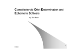
In the circular-restricted three-body model, there are two massive bodies in orbit about their mutual
barycenter, as depicted in Figure 1. To simplify the model, each body orbits the barycenter in the same
plane in perfectly circular orbits. A spacecraft with infinitesimal mass experiences forces due to the
gravitational influence of both bodies simultaneously, and the two bodies are approximated as point
masses. The more massive body is labeled P1 and the other is P2 . The coordinate frame has its origin
at the barycenter and rotates with the two bodies so that P1 and P2 are always on the x-axis, with the
positive x-direction going from P1 to P2 . The positive y-axis is parallel to the velocity vector of P2 . The
three-body gravitational parameter is called µ:
µ=
m2
.
m1 + m2
(11)
where m1 is the mass of P1 and m2 is the mass of P2 . The mass of the primaries is nondimensionalized
so that the mass of P2 is defined to be µ and the mass of P1 is 1 - µ. One nondimensional length unit
(LU) is equal to the distance between the two primaries, so the distance along the x-axis from the origin
to P1 is -µ LU and from the origin to P2 is 1 - µ LU. The time unit (TU) is defined such that P2 orbits
around P1 in 2π TU.
The equations of motion for the CRTBP are (Murray and Dermott, 1999)
where
x+µ−1
x+µ
ẍ − 2ẏ = x − (1 − µ) 3 − µ
r1
r23
1−µ
µ
ÿ + 2ẋ =
1−
− 3 y
3
r1
r
2
µ−1
µ
z̈ =
− 3 z,
3
r1
r2
p
p
r1 = (x + µ)2 + y 2 + z 2
and
r2 = (x + µ − 1)2 + y 2 + z 2 .
(12)
(13)
The functions CRTBP DE.m and rot inert.m can be used to convert from an inertial frame to
the rotating, non-dimensional frame used in the CRTBP ODE functions. See Section 6 for more details
on those functions.
22
5.1
Mathematical Theory for ODE Functions
5
ODE FUNCTIONS
Figure 1: Diagram of the Circular Restricted Three-Body Problem with a rotating, nondimensional
coordinate frame.
The origin of the coordinate frame for the CRTBP grav-type functions is not at the three-body
barycenter like the other CRTBP models, but the origin is at the center of the secondary, with the x-axis
pointed toward the primary and the z-axis perpendicular to the orbit plane of the primary and secondary.
Note that this reference frame is rotated 180◦ about the z-axis from the other CRTBP models. These
new axes are called x̃, ỹ, and z̃ and the coordinates can be converted like this:
x̃
ỹ
z̃
x̃˙
ỹ˙
z̃˙
=
=
=
=
=
=
−x − (1 − µ)
−y
z
−ẋ
−ẏ
ż.
(14)
(15)
The converted equations of motion are
x̃
x̃ − 1
x̃¨ − 2ỹ˙ = x̃ − (1 − µ) − (1 − µ) 3 − µ 3
r1
r2
1−µ
µ
ỹ¨ + 2x̃˙ =
1−
− 3 ỹ
3
r1
r
2
µ−1
µ
z̃¨ =
− 3 z̃,
3
r1
r2
23
(16)
5.1
Mathematical Theory for ODE Functions
where
5.1.3
r1 =
5
p
(1 − x̃)2 + ỹ 2 + z̃ 2
and
ODE FUNCTIONS
r2 =
p
x̃2 + ỹ 2 + z̃ 2 .
(17)
JPL Ephemeris System, “DE ”
The JPL planetary ephemeris model. DE ODE functions are in the ICRF inertial reference frame
centered on a user-specified planetary body, or the Sun. The reference plane of the ICRF is the mean
equator of J2000, and the reference vector is the dynamic equinox of J2000. The positions and velocities
of all the planets are obtained from JPL DE ephemerides: DE403 (Standish et al., 1995) or DE405
(Standish, 1998). These ephemerides contain lunar orientation angles that can be used to rotate from
the inertial Moon-centered coordinates to Moon-fixed coordinates. The ephemerides also contain Earth
Nutation angles for converting between inertial and fixed coordinates. The binary ephemeris file for
DE403 is called ephem.403 and the binary file for DE405 is called ephem.405.
The code used to create the ephemeris files and to perform the interpolation was adapted from work
by CCAR graduate student Greg Lehr and code by Mark Hoffman (Hoffman, 1998) at
ftp://ssd.jpl.nasa.gov/pub/eph/export/C-versions/hoffman/
The ephemeris data files were obtained from
ftp://ssd.jpl.nasa.gov/pub/eph/export/
In the DE-type functions, the acceleration due to the central body is
r̈2body = −
µr
,
r3
(18)
where r is the position vector of the spacecraft with respect to the planet’s center of mass. r is the
magnitude of that vector. µ is the gravitational parameter of the body.
The acceleration due to other planetary bodies, or ‘third bodies’ (Tapley et al., 2004) is
r3,sat r⊕,3
r̈3body = −µ3body
+ 3
,
(19)
3
r3,sat
r⊕,3
where µ3body is the gravitational parameter of the third-body, r3,sat is the vector from the third-body to
the satellite, r⊕,3 is the vector from the central body to the third-body, and r3,sat and r⊕,3 are the vector
magnitudes.
By default, the gravitational parameters are taken from the JPL ephemeris, as shown in Table 1.
The user can provide extras.mu as an optional input to the DE-type ODE functions, and its value
will be used as the gravitational parameter for the body that is the center of integration. The gravitational parameters for the other planets will remain at their default values. The value in extras.mu
will also be used instead of the gravitational parameter in a gravity file, if the ODE function requires it.
24
5.1
Mathematical Theory for ODE Functions
5
ODE FUNCTIONS
Table 1: DEFAULT GRAVITATIONAL PARAMETERS FROM JPL EPHEMERIDES.
Planet
DE403
DE405
Mercury
2.20320804864179×10⁴
Venus
3.2485859882646×10⁵
Earth+Moon 4.03503234715983×10⁵
Mars
4.28283142580671×10⁴
Jupiter
1.26712767857796×10⁸
3.79406260611373×10⁷
Saturn
Uranus
5.79454900707188×10⁶
Neptune
6.83653406387926×10⁶
Pluto
9.81600887707005×10²
Sun
1.32712440017987×10¹¹
Earth
3.98600435608103×10⁵
Moon
4.90279910787977×10³
2.20320804864179×10⁴
3.2485859882646×10⁵
4.03503233479087×10⁵
4.28283142580671×10⁴
1.26712767857796×10⁸
3.79406260611373×10⁷
5.79454900707188×10⁶
6.83653406387926×10⁶
9.81600887707005×10²
1.32712440017987×10¹¹
3.98600432896939×10⁵
4.90280058214776×10³
Units are km3 /s2
5.1.4
Mass Concentration Gravity Field, “PointMasses ”
The mass concentration model is a gravity field where the total acceleration is determined by a collection of point masses, each with a given mass and location. The net acceleration is
r̈pointmass = −G
X mi r̄i
i
ri3
,
(20)
where mi is the mass of i-th point and r̄i is the vector from the point mass to the satellite. ri is the
magnitude of the r̄i vector. Note, this is essentially the sum of the two-body accelerations due to each
point mass. In TurboProp,
G = 6.67428 × 10⁻²⁰ km3 /(kg · sec2 ).
(21)
This value was selected based on Mohr et al. (2007). Note, based on the units of this value, all input
values must be in km and seconds.
The definition of the point masses, sometimes referred to as mascons, is provided to the integrator in
the extras.gravfile option. The file format is rather straightforward, with one header line and a
collection of data lines. The format of the header and data are provided in Tables 2 and 3, respectively.
The given mass for each point is represented as a fraction of the total mass of the system. The total
mass is derived from the gravitation parameter given in the header line. Locations of the point masses
are defined in the planet fixed frame in spherical coordinates, and rotated based on the extras.EOP
over time. An example file (example.ptm) is provided in the Data/ directory.
25
5.1
Mathematical Theory for ODE Functions
5
ODE FUNCTIONS
Table 2: HEADER LINE FORMAT FOR POINT MASS FILES
C format string: "%le, %d"
Parameter Description
Format
Units
Gravitation Parameter of the “planet” Scientific notation km3 /s2
Number of point masses
Integer
N/A
Table 3: DATA LINE FORMAT FOR POINT MASS FILES
C format string: "%le, %le, %le, %le"
Parameter Description
Format
Fraction of total mass for given point
Point Radius
Point Latitude
Point Longitude
5.1.5
Units
Scientific Notation N/A (fraction of whole)
Scientific Notation
km
Scientific Notation
degrees
Scientific Notation
degrees
Spherical Harmonic Gravity Field, “ grav”
A spherical harmonic gravity field model is used for one of the planetary bodies. Current ODE functions are only compatible with Earth and lunar gravity fields. In other words, Earth-fixed and lunarfixed orientations are the only ones currently available. Two lunar gravity fields are from Konopliv
et al. (2001). The lunar LP100K gravity field coefficients file is called jgl100k1.sha and the lunar
LP150Q coefficients file is called jgl150q.sha. jgl150q.sha has the permanent tide correction
already applied to J2 and C2,2 . The GLGM-2 gravity field is from Lemoine et al. (1997) and is called
GLGM2.sha. The gravity model for the Earth comes from the GRACE mission (Tapley et al., 2005)
and is called GGM02C.sha. The JGM-3 gravity field (Tapley et al., 1996) is called JGM3.sha, while
the WGS-84 gravity field (NGA, 2000) is named WGS84.sha.
The gravity field format was based after the file format for the lunar gravity field jgl100k1.sha
found at
http://pds-geosciences.wustl.edu/missions/lunarp/shadr.html
The first line is a header and contains eight parameters, three of which are used and the rest discarded.
The parameters are shown in Table 4.
Note that these parameters are comma-delimited. If extras.mu was not input by the user, the
gravitational parameter and reference radius from this header line will be used for all gravity calculations for the central body. The user can provide extras.mu and extras.radius to override the
parameters in the gravity header line.
After the header line, “data lines” contain the gravity field coefficients. These coefficients are
comma-delimited also, and are described in Table 5.
26
5.1
Mathematical Theory for ODE Functions
5
ODE FUNCTIONS
Table 4: HEADER LINE FORMAT FOR GRAVITY FIELD FILES
C format string: " %le, %le, %le, %d, %d, %d, %le, %le"
Parameter Description
Format
Units
Reference radius of the planet
Scientific notation km
Gravitational parameter
Scientific notation km3 /s2
Gravitational parameter uncertainty Scientific notation km3 /s2 (discarded)
Degree of model field
Integer
N/A (discarded)
Order of model field
Integer
N/A (discarded)
Normalization
Integer
0 = unnormalized
1 = normalized
Scientific notation degrees (discarded)
Reference longitude, normally 0
Reference latitude, normally 0
Scientific notation degrees (discarded)
Table 5: DATA LINE FORMAT FOR GRAVITY FIELD FILES
C format string: " %d, %d, %le, %le, %le, %le"
Parameter Description
Degree index n
Order index m
Coefficient Cn,m
Coefficient Sn,m
Uncertainty in coefficient Cn,m
Uncertainty in coefficient Sn,m
Format
Integer
Integer
Scientific Notation
Scientific Notation
Scientific Notation
Scientific Notation
The Earth and the Moon are the only planets supported in DE grav-type derivative functions, so
extras.center should only be 11 or 12 for those functions.
The gravity field is modeled using U , an aspherical potential function excluding the two-body term
(Gottlieb (1993)),
n n
∞
hz i
µXX R
U (x, y, z) =
Ān,m
{C̄n,m Ēm + S̄n,m F̄m }
(22)
r n=2 m=0 r
r
where
r=
p
x2 + y 2 + z 2
x
Ēm = Ē1 Ēm−1 − F̄1 F̄m−1 , Ē0 = 1, Ē1 =
r
y
F̄m = F̄1 Ēm−1 + Ē1 F̄m−1 , F̄0 = 0, F̄1 = .
r
27
(23a)
(23b)
(23c)
5.1
Mathematical Theory for ODE Functions
5
ODE FUNCTIONS
Note this form is defined in terms of the Cartesian, not spherical, coordinates. Thus, this formulation
does not contain the singularity at the poles present in the classical formulation presented in Vallado
and McClain (2001), and elsewhere. R is the radius of the central body, µ is the gravitational parameter
of the central body, and n and m are the degree and order of the spherical harmonic model respectively.
C̄n,m and S̄n,m are normalized coefficients describing themagnitude
of the spherical harmonics, and
z
are specific to the gravity field model being used. Ān,m α = r is a normalized, derived Legendre
function computed using the following recursion:
Ā0,0 [α] = 1
√
Ā1,0 [α] = α 3
√
3
Ā1,1 [α] =
r
2n + 1
Ān,n [α] =
Ān−1,n−1 [α]
n>1
2n
Bn,m
Ān,m [α] = αBn,m Ān−1,m [α] −
Ān−2,m [α]
Bn−1,m
m<n
(24)
where
s
Bn,m =
(2n + 1)(2n − 1)
.
(n + m)(n − m)
(25)
Since the Bn,m coefficients are not a function of α, they are precomputed at software initialization and
stored in memory for future use. This formulation of the derived Legendre functions is adapted from
personal correspondence with Dr. Bob Schutz of the University of Texas Center for Space Research
and from his book Satellite Dynamics: Theory and Application current being written with G. Giacaglia.
This adaptation to the formulation in Schutz’s book was based on Lundberg and Schutz (1988), and is
consistent with Gottlieb (1993).
The acceleration in body-fixed coordinates, r̈, is found by taking the gradient of the potential in
cartesian coordinates. As derived in Gottlieb (1993), the following equations summarize the algorithm:
a1 =
a2 =
n
∞ n X
X
R
n=2
∞ X
n=2
a3 =
R
r
m=1
n X
n
r
(26a)
mĀn,m Sn,m Ēm−1 − Cn,m F̄m−1
(26b)
(26c)
m=1
∞ n X
n
X
R
n=2
a4 =
r
mĀn,m Cn,m Ēm−1 + Sn,m F̄m−1
Ān,m+1 Γn,m Cn,m Ēm + Sn,m F̄m
m=0
∞ n X
n
X
R
(n + m + 1)Ān,m Cn,m Ēm + Sn,m F̄m
r
m=0
a
r 1
µ z
r̈ = − 2
a3 + a4
− a2
r
r
r
a3
(26d)
n=2
28
(26e)
5.1
Mathematical Theory for ODE Functions
where
r
Γn,m = Πn,m+1 /Πn,m =
since
s
Πn,m =
5
ODE FUNCTIONS
(n + m + 1)(n − m)(2 − δ0m )
2
(n + m)!
.
(n − m)!(2 − δ0m )(2n + 1)
(27)
(28)
In the software, Γn,m is precomputed and stored at initialization.
The equations of motion are integrated in the inertial frame, so the spacecraft state vector must be
converted from the inertial frame to the body-fixed frame before computing the accelerations. After
computing the body-fixed accelerations, they must be converted back into the inertial frame. The
conversion from an inertial to a fixed frame is described in detail for both the Moon and the Earth in
Section 5.1.6.
5.1.6
Inertial-Fixed Conversions
Lunar Orientation The conversion between inertial and fixed position for the Moon is computed
using the Lunar Librations from the DE403 (or DE405) ephemeris. The DE403 ephemeris is best for
the Moon, and using Julian Ephemeris Date (JED) is technically more correct than using Terrestrial
Time (TT) when interpolating the Lunar Librations. The Lunar Librations are three Euler angles, φ,
ψ, and θ, according to Newhall and Williams (1997). φ is the rotation angle along the Earth’s mean
equator of J2000 from the equinox to the ascending node of the lunar equator. θ is the inclination of the
lunar equator with respect to the Earth’s mean equator. ψ is the angle along the lunar equator from the
node to a longitude of zero. Figure 2 from Newhall and Williams shows the angles graphically. Make
sure not to confuse the φ mentioned here with the φ that represents latitude. The conversion for velocity
is included in the discussion, even though it is not used to compute acceleration due to the gravity field.
Using these angles from the JPL ephemeris, the conversion from the Moon-Centered inertial position
and velocity (based on ICRF) to Moon-Centered Moon-Fixed (MCMF) would be
rM CM F = γrICRF
vM CM F = γvICRF + γ̇rICRF .
The rotation matrices ROT 1, ROT 2, and ROT 3 are
1
0
0
0 cos(θ) sin(θ)
ROT 1(θ) =
0 − sin(θ) cos(θ)
cos(θ) 0 − sin(θ)
1
0
ROT 2(θ) = 0
sin(θ) 0 cos(θ)
cos(θ) sin(θ) 0
ROT 3(θ) = − sin(θ) cos(θ) 0
0
0
1
29
(29)
(30)
(31)
.
(32)
5.1
Mathematical Theory for ODE Functions
5
ODE FUNCTIONS
Figure 2: The equatorial system in which the Libration Eular angles are defined. (The value of φ would
be negative as shown, credit: Newhall and Williams (1997).)
Using these rotation matrices, γ for the Moon is
γ = ROT 3(ψ)ROT 1(θ)ROT 3(φ).
Multiplying the three rotation matrices together gives:
C(ψ)C(φ) − S(ψ)C(θ)S(φ)
C(ψ)S(φ) + S(ψ)C(θ)C(φ) S(ψ)S(θ)
γ = −S(ψ)C(φ) − C(ψ)C(θ)S(φ) −S(ψ)S(φ) + C(ψ)C(θ)C(φ) C(ψ)S(θ) ,
S(θ)S(φ)
−S(θ)C(φ)
C(θ)
(33)
(34)
where C and S represent sine and cosine functions, respectively.
The GEONS Mathematical Specification by Long and Lee (2006) gives the technique used to find γ̇
in Eqn. 3.2-91a, although different angles are used here. The time derivative of γ is taken, assuming
dφ
= 0 and dθ
= 0:
dt
dt
−S(ψ)C(φ) − C(ψ)C(θ)S(φ) −S(ψ)S(φ) + C(ψ)C(θ)C(φ) C(ψ)S(θ)
γ̇ = ψ̇ −C(ψ)C(φ) + S(ψ)C(θ)S(φ) −C(ψ)S(φ) − S(ψ)C(θ)C(φ) −S(ψ)S(θ) . (35)
0
0
0
Long and Lee (2006) give ψ̇ a value of 0.2299708331 radians per day.
The conversion from Moon-Centered Moon-Fixed (MCMF) to Moon-Centered inertial (based on
ICRF) would be:
rICRF = [γ]T rM CM F
vICRF = [γ]T vM CM F + [γ̇]T rM CM F .
30
(36)
5.1
Mathematical Theory for ODE Functions
5
ODE FUNCTIONS
Earth Orientation The conversion from an Earth-centered inertial frame (GCRF) to an Earth-centered, Earth-fixed frame (ITRF) is performed using the 1976 IAU Precession, 1980 IAU Nutation (with
IERS corrections), Earth rotation parameters, and Polar Motion. The conversion for velocity is included
in the discussion, even though it is not used to compute acceleration due to the gravity field.
1976 IAU Precession To perform the conversion from inertial to fixed coordinates for the Earth, a
position vector in the inertial frame, rGCRF , must first be rotated into a Mean of Date (MOD) inertial
frame. This is done in TurboProp using the 1976 IAU Precession model given in Eqn. 3-56 in Vallado
and McClain (2001).
ζ = 2306.2181”TT T + 0.30188TT2T + 0.017998TT3T
Θ = 2004.3109”TT T − 0.42665TT2T − 0.041833TT3T
z = 2306.2181”TT T + 1.09468TT2T + 0.018203TT3T
(37)
The units must be changed to radians. TT T is the number of Julian centuries from J2000 in Terrestrial
Time (TT).
JDT T − 2451545.0
TT T =
(38)
36525
The equations for ζ, Θ, and z are nominally written using TJED , but TT T can be used with no discernible
change in results.
The conversion for position and velocity from GCRF to MOD is (Vallado and McClain (2001) Eqn.
3-57):
rM OD = ROT 3(−z)ROT 2(Θ)ROT 3(−ζ)rGCRF
vM OD = ROT 3(−z)ROT 2(Θ)ROT 3(−ζ)vGCRF .
(39)
Note that this MOD frame is different than the MOD frame obtained when converting from the Mean
J2000 inertial frame.
The three rotation matrices shown above are combined and called [P RE]:
[P RE] = ROT 3(−z)ROT 2(Θ)ROT 3(−ζ).
(40)
1980 IAU Theory of Nutation + corrections Next, a conversion is performed from inertial MOD,
rM OD , to inertial True of Date (TOD) coordinates, rT OD . This is done in TurboProp using the 1980
IAU Theory of Nutation.
First, compute the mean obliquity (Vallado and McClain (2001) Eqn. 3-52):
¯ = 23.439291◦ − 0.0130042TT T − 1.64 × 10⁻⁷ TT2T + 5.04 × 10⁻⁷ TT3T .
(41)
The nutation in longitude, ∆Ψ, and the nutation in obliquity, ∆ are normally computed from a series of 106 terms. However, TurboProp uses the interpolated nutation parameters from the JPL DE
ephemerides instead of computing all 106 terms in the trigonometric series. Due to errors in 1976
IAU Precession and 1980 IAU Nutation, the International Earth Rotation Service (IERS) publishes corrections to the nutation parameters called ∂∆Ψ1980 and ∂∆1980 . These corrections also account for
31
5.1
Mathematical Theory for ODE Functions
5
ODE FUNCTIONS
differences between the GCRF frame used in TurboProp and the mean J2000 frame normally used with
the 1976 IAU Precession and 1980 IAU Nutation models. These nutation correction parameters are
computed from the extras.EOP vector (see Section 4.15.11).
∆Ψ1980 = ∆Ψ + ∂∆Ψ1980
∆1980 = ∆ + ∂∆1980
= ¯ + ∆1980
(42)
The conversion from MOD to TOD is:
rT OD = ROT 1(−)ROT 3(−∆Ψ1980 )ROT 1(¯)rM OD
vT OD = ROT 1(−)ROT 3(−∆Ψ1980 )ROT 1(¯)vM OD .
(43)
The rotation ROT 1(−)ROT 3(−∆Ψ1980 )ROT 1(¯) is called [N U T ].
Earth Rotation or Sidereal Time This conversion accounts for the instantaneous orientation of
the Earth about its rotation axis. First, Greenwich Mean Sidereal Time, θGM ST , must be computed
(Vallado and McClain (2001) Eqn. 3-44).
θGM ST = θGM ST 0h + ω⊕prec U T 1
(44)
The U T 1 in the equation is the time past midnight in UT1. θGM ST 0h is the Greenwich Mean Sidereal
Time at midnight, UT1,0h, or 00:00:00.0 UT1 on the date of interest. θGM ST 0h is computed using the
equation (Vallado and McClain (2001) Eqn. 3-43)
θGM ST 0h = 100.4606184◦ + 36000.77005361TU T 1,0h + .00038793TU2 T 1,0h − 2.6 × 10⁻⁸ TU3 T 1,0h . (45)
The units must be changed to radians. TU T 1,0h is the number of Julian Centuries elapsed from J2000 to
00:00:00.0 UT1 on the date of interest.
TU T 1,0h =
JDU T 1,0h − 2451545.0
36525
(46)
JDU T 1,0h is the Julian Date at 00:00:00.0 UT1 for the date of interest.
JDU T 1 is computed from JDT T in the following way:
JDU T 1 = JDT T + (−32.184 + [U T 1 − U T C] − Nleap )/86400.
(47)
where −32.184 is the conversion from TT to TAI, Nleap is the number of leap seconds needed to convert
from TAI to UTC, and [U T 1 − U T C] is the conversion from UTC to UT1. Nleap and [U T 1 − U T C]
are computed from the EOP parameters in extras.EOP (see Section 4.15.11).
ω⊕prec is the Earth’s mean angular rotation, and can be computed using Eqn. 3-38 in
Vallado and McClain (2001), which gives revolutions per day.
ω⊕prec = 1.002737909350795 + 5.9006 × 10⁻¹¹ TT T − 5.9 × 10⁻¹⁵ TT2T
32
(48)
5.1
Mathematical Theory for ODE Functions
5
ODE FUNCTIONS
The units must be converted to radians, and TT T is the number of Julian centuries (TT) elapsed since
J2000. The equation is nominally written using TU T 1 , but TT T can be used with no discernible change
in results.
After computing θGM ST , it is necessary to compute the Greenwich Apparent Sidereal Time, θAST ,
using the equation of the equinoxes (Vallado and McClain (2001) Eqn. 3-65).
EQequinox = ∆Ψ cos(¯) + 0.00264” sin(Ω$ ) + 0.000063 sin(2Ω$ )
θAST = θGM ST + EQequinox
(49)
(50)
Ω$ can be found using Eqn. 3-54 in Vallado and McClain (2001).
Ω$ = 125.04455501◦ −1934.1361851TT T +.0020756TT2T +2.139×10⁻⁶ TT3T −1.650×10⁻⁸ TT4T (51)
The conversion from the TOD to a Pseudo-Earth-fixed (PEF) is (Vallado and McClain (2001) Eqn.
3-70)
rP EF = ROT 3(θAST )rT OD .
(52)
ROT 3(θAST ) will be called [ST ]. For the velocity, the rotation rate of the Earth must be computed
using the excess Length Of Day (LOD) (Vallado and McClain (2001) Eqn. 3-69).
ω⊕ = 7.29211514670698 × 10⁻⁵ (1 − LOD)
(53)
LOD is a parameter in the extras.EOP vector (see Section 4.15.11) and has units of days. For
units of seconds, then the term in the equation above must be changed to LOD/86400. Using ω⊕ , the
˙ ] is
conversion matrix [ST
−ω⊕ sin(θAST ) ω⊕ cos(θAST ) 0
˙ ]=
[ST
(54)
−ω⊕ cos(θAST ) −ω⊕ sin(θAST ) 0 .
0
0
0
Finally, the velocity is transformed from TOD to PEF.
˙ ]rT OD
vP EF = [ST ]vT OD + [ST
(55)
Polar Motion To convert from PEF to the Earth-fixed International Terrestrial Reference Frame
(ITRF), a polar motion rotation must be applied. xp and yp are the coordinates describing the motion of
the Earth’s rotation axis with respect to the Earth’s crust. These polar motion parameters are computed
from the extras.EOP vector (see Section 4.15.11). Using xp and yp , the conversion from PEF to
ITRF is (Vallado and McClain (2001) Eqn. 3-68)
1
0 xp
1 −yp
rIT RF = 0
(56)
rP EF .
−xp yp 1
The matrix above will be called [P M ], and the velocity conversion is
vIT RF = [P M ]vP EF .
33
(57)
5.1
Mathematical Theory for ODE Functions
5
ODE FUNCTIONS
To summarize the conversion from GCRF to ITRF:
rIT RF = [P M ][ST ][N U T ][P REC]rGCRF
˙ ][N U T ][P REC]rGCRF + [P M ][ST ][N U T ][P REC]vGCRF .
vIT RF = [P M ][ST
(58)
˙ ][N U T ][P REC], and the notation is
Let γ be [P M ][ST ][N U T ][P REC] and let γ̇ be [P M ][ST
shortened and the conversion is
rIT RF = [γ]rGCRF
vIT RF = [γ̇]rGCRF + [γ]vGCRF .
(59)
Converting back to the inertial frame (GCRF) would be
rGCRF = [γ]T rIT RF
vGCRF = [γ̇]T rIT RF + [γ]T vIT RF .
5.1.7
(60)
Solar Radiation Pressure, “ SRP”
A solar radiation pressure model is included in the force model for the satellite. This is based on
a constant area, constant reflectance model. The reflectance is also included in the spacecraft state
vector. The shadow model determines an approximate value of the percentage of the Sun’s face visible
at the spacecraft location. The radii of the bodies used in the shadow model are taken from Vallado
and McClain (2001) or the JPL ephemeris. The value of solar radiation pressure is adjusted based on
distance from the Sun.
The acceleration due to SRP is
A r
r̈SRP = pSR cR sat .
m |rsat |
(61)
cR is the reflectivity of the spacecraft. A is the cross-sectional area of the spacecraft facing the Sun in
square meters. m is the mass of the spacecraft in kilograms. rsat is the vector from the center of the
Sun to the spacecraft. pSR is the pressure of solar radiation in Pa. This is about 4.53 × 10⁻⁶ Pa at one
AU, and is found by dividing the solar constant (flux in W/m2 ) by the speed of light (p. 544 Vallado
and McClain (2001)).
1358 W/m2
(62)
pSR,AU =
299, 792, 458m/s
For varying distances from the Sun, pSR would be
pSR = pSR,AU
(149, 597, 870 km)2
.
|rsat |2
(63)
rsat should be in km. A factor ` can be applied to represent the fraction of the Sun’s face that is
visible. When km and km/s are the units used for position and velocity, respectively, the acceleration
due to SRP is
A
rsat
1 km
2
r̈SRP = cR `
(149, 597, 870 km) pSR,AU
.
(64)
m
1000 m |rsat |3
34
5.1
Mathematical Theory for ODE Functions
5
ODE FUNCTIONS
` = 1 when there is a clear line of sight vector between the spacecraft and the Sun, and ` = 0 when
the Sun’s light is blocked by a body. When determining the line of sight, it was assumed that the center
planet (extras.center) is the only body that would eclipse the Sun. The angle between the center
of the planet and the center of the Sun is called ς and is found using the dot product.
rsat · r$sat
−1
ς = cos
(65)
|rsat ||r$sat |
rsat is the vector from the center of the Sun to the spacecraft and r$sat is from the central body to the
spacecraft. |rsat | and |r$sat | are the magnitudes of those vectors. The angle between the center and
limb for the two bodies are found using these equations, assuming that the bodies are spherical.
R
−1
ς = sin
(66)
|rsat |
R$
−1
(67)
ς$ = sin
|r$sat |
R and R$ are the radii of the primary bodies. Table 6 shows the values TurboProp uses for the planet
radii. Note that extras.radius does not override these values for eclipse computations. Most
radius values were taken from Appendix D of Vallado and McClain (2001), but the radii for Mercury,
Venus, and Mars were taken from the DE405 ephemeris. “Earth+Moon” represents the Earth/Moon
barycenter instead of an eclipsing body, so it is given a radius of zero.
Table 6: PLANETARY RADII FOR ECLIPSE COMPUTATIONS.
Planet
radius (km)
Mercury
Venus
Earth+Moon
Mars
Jupiter
Saturn
Uranus
Neptune
Pluto
Sun
Earth
Moon
2439.76
6052.3
0
3397.515
71,492.0
60,268.0
25,559.0
24,764.0
1151.0
696,000.0
6378.1363
1738.0
Units are km3 /s2
35
5.1
Mathematical Theory for ODE Functions
5
ODE FUNCTIONS
The relations below were used in determining `.
1,
ς −ς
$ + 1,
`=
2
2ς
0,
ς ≥ ς$ + ς
ς$ − ς ≤ ς < ς$ + ς
(68)
ς < ς$ − ς
This is based on the assumption that ς$ ς . If that is false, it only negatively affects the computation
of ` when the Sun is partially eclipsed.
5.1.8
Atmospheric Drag, “ drag”
The acceleration due to drag for the TwoBody-type derivative functions is computed using the equations
CD A
ρVa,x |Va |
2 m
CD A
ÿdrag = −
ρVa,y |Va |
(69)
2 m
CD A
z̈drag = −
ρVa,z |Va |,
2 m
A
where CD is the coefficient of drag, which is part of the state vector. m
is the area-to-mass ratio
of the spacecraft, specified by extras.A m. Va,x , Va,y , and Va,z are the velocity components of the
spacecraft with respect to the atmosphere (assumed to rotate with the planet). |Va | is the magnitude of
that vector.
The atmospheric density, ρ, at a certain radius from the center of the body, r, is computed using the
parameters in extras.atmos.
r0 −r
(70)
ρ(r) = ρ0 e( H )
ẍdrag = −
See Section 4.15.12 for more information.
In TwoBody drag-type derivative functions, The atmospheric-relative velocity vector is computed
from the inertial velocities (ẋ, ẏ, and ż) and positions (x and y) using the equations
Va,x = ẋ + θ̇y
Va,y = ẏ − θ̇x
Va,z = ż.
(71)
θ̇ is the rotation rate of the central body and is contained in extras.EOP (see Section 4.15.11).
The acceleration due to drag for the DE-type derivative functions is computed using the equations
A
ρVa,x |Va |
m
A
= −500CD ρVa,y |Va |
m
A
= −500CD ρVa,z |Va |.
m
ẍdrag = −500CD
ÿdrag
z̈drag
36
(72)
5.1
Mathematical Theory for ODE Functions
5
ODE FUNCTIONS
The 500 coefficient is the conversion factor 1000 divided by two. The conversion factor is needed
A
because the units for m
are m2 /kg, the units for ρ are kg/m3 , and the units for Va are km/s.
In DE drag-type derivative functions, The atmospheric-relative velocity vector is computed using
the equation (Vallado and McClain (2001) p. 523)
Va = ṙ − ω × r,
(73)
where ṙ is the inertial velocity vector, r is the inertial position vector, and ω is the Earth’s rotation
vector.
γ(3,
1)
ω1
ω = ω2 = ω⊕ γ(3, 2)
(74)
ω3
γ(3, 3)
ω⊕ is the rotation rate of the Earth, and it is multiplied by the third row of the γ matrix used to convert
a position from inertial to fixed (see Section 5.1.6).
Applying the cross product gives
Va,x = ẋ − ω2 z + ω3 y
Va,y = ẏ − ω3 x + ω1 z
Va,z = ż − ω1 y + ω2 x.
(75)
For DE drag-type functions, ω⊕ is computed automatically, and is not supplied by the user.
5.1.9
State Transition Matrix, “ stm”
In stm-type derivative functions, the state vector is augmented with a state transition matrix (STM).
When the state vector includes a state transition matrix (STM), it should be added on to the end of the
state vector in column order. As an example assignment in MATLAB with a six-element state and a
STM, you could type
y0 = [x y z dx dy dz]’;
(this assigns the state)
y0(6+1:6+36) = reshape(eye(6),36,1);
(this adds on the STM)
State deviations at time t may be mapped back to the initial epoch, tk , with the state transition matrix
Φ.
x(t) = Φ(t, tk )xk
(76)
A sample state transition matrix for two-dimensions of position and velocity would be
∂x ∂x ∂x ∂x
∂xk ∂yk ∂ ẋk ∂ ẏk
∂y
∂y
∂y
∂y
∂xk ∂yk ∂ ẋk ∂ ẏk
Φ(t, tk ) =
∂ ẋ ∂ ẋ ∂ ẋ ∂ ẋ .
∂x ∂y ∂ ẋ ∂ ẏ
k
k
k
k
∂
ẏ
∂
ẏ
∂
ẏ
∂
ẏ
∂xk ∂yk ∂ ẋk ∂ ẏk
37
(77)
5.1
Mathematical Theory for ODE Functions
5
ODE FUNCTIONS
The state transition matrix is integrated along with the state using the following relation:
Φ̇(t, tk ) = A(t)Φ(t, tk )
A(t) =
where
A=
∂ ẋ
∂x
∂ ẏ
∂x
∂ ż
∂x
..
.
∂ z̈
∂x
∂ ẋ
∂y
∂ ẏ
∂y
∂ ż
∂y
∂F(X, t)
,
∂X(t)
∂ ẋ
···
∂z
∂ ẏ
∂z
∂ ż
∂z
...
···
and is of the form:
∂ ẋ
∂ ż
.. .
.
∂ z̈
∂ ż
(78)
(79)
Although it isn’t shown, the parameters CD and cR would also be included in the state transition
matrix if they were in the state vector.
The following sections describe how these partials are computed.
Central Body STM To include the two-body acceleration in the variational equations used to create
matrix A, the partials of the two-body portion of r̈ with respect to r are computed in this manner:
µx2
µ
∂ ẍ2body
= 3 5 − 3
∂x
r
r
µxy
∂ ÿ2body
= 3 5
∂x
r
∂ z̈2body
µxz
= 3 5
∂x
r
∂ ẍ2body
µxy
= 3 5
∂y
r
µy 2
µ
∂ ÿ2body
= 3 5 − 3
∂y
r
r
µyz
∂ z̈2body
= 3 5
∂y
r
∂ ẍ2body
µxz
= 3 5
∂z
r
µyz
∂ ÿ2body
,
= 3 5
∂z
r
µz 2
µ
∂ z̈2body
= 3 5 − 3
∂z
r
r
(80)
where x, y, and z are the inertial position vector from the center of mass of the body to the spacecraft
and r is the magnitude of that vector. µ is the gravitational parameter of the central body. ẍ, ÿ, and z̈
are the accelerations in the x, y, and z-directions, respectively.
Third Body STM To include the third-body acceleration in the variational equations used to create
matrix A, the partials of the third-body portion of r̈ with respect to r are computed in this manner:
∂ ẍ3body
µ 3 x2 µ 3
= 3 53 − 3
∂x3
r3
r3
∂ ÿ3body
µ 3 x3 y 3
= 3
∂x3
r35
∂ z̈3body
µ3 x3 z3
= 3
∂x3
r35
∂ ẍ3body
µ3 x 3 y 3
= 3
∂y3
r35
∂ ÿ3body
µ3 y 2 µ3
= 3 53 − 3
∂y3
r3
r3
∂ z̈3body
µ3 y3 z3
= 3 5
∂y3
r3
38
∂ ẍ3body
µ3 x3 z3
= 3
∂z3
r35
∂ ÿ3body
µ3 y3 z3
.
= 3 5
∂z3
r3
∂ z̈3body
µ3 z 2 µ3
= 3 53 − 3
∂z3
r3
r3
(81)
5.1
Mathematical Theory for ODE Functions
5
ODE FUNCTIONS
x3 , y3 , and z3 are the inertial position vector from the center of mass of the third-body to the spacecraft and r3 is the magnitude of that vector. µ3 is the gravitational parameter of the third-body. These
computations are repeated for each third-body included in the equations of motion. Notice that this is
the same as for the central body.
CRTBP STM
are
For the Circular-restricted Three-body Problem, the partials used to create matrix A
∂ ẍCRT BP
∂x
∂ ẍCRT BP
∂y
∂ ẍCRT BP
∂z
∂ ẍCRT BP
∂ ẏ
∂ ÿCRT BP
∂x
∂ ÿCRT BP
∂y
∂ ÿCRT BP
∂z
∂ ÿCRT BP
∂ ẋ
∂ z̈CRT BP
∂x
∂ z̈CRT BP
∂y
∂ z̈CRT BP
∂z
3(1 − µ)(µ + x)2 µ − 1
3µ(µ − 1 + x)2
3
+
= 1+
−
r
+
2
r25
r15
r13
µ(µ − 1 + x) (1 − µ)(µ + x)
= 3y
+
r25
r15
µ(µ − 1 + x) (1 − µ)(µ + x)
= 3z
+
r25
r15
= 2
∂ ẍCRT BP
∂y
3µy 2
3(1 − µ)y 2 µ − 1
= 1 + 5 − r23 +
+
r2
r15
r13
µ
1−µ
= 3yz
+
5
r2
r15
=
(82)
= −2
∂ ẍCRT BP
∂z
∂ ÿCRT BP
=
∂z
3µz 2
3(1 − µ)z 2 µ − 1
3
=
−
r
+
+
.
2
r25
r15
r13
=
See Section 5.1.2 for details on the notation.
For the Circular-restricted Three-body Problem centered at the secondary, with the x̃ axis pointed
toward the primary, the partials used to create matrix A are
39
5.1
Mathematical Theory for ODE Functions
∂ x̃¨CRT BP
∂ x̃
∂ x̃¨CRT BP
∂ ỹ
∂ x̃¨CRT BP
∂ z̃
∂ x̃¨CRT BP
∂ ẏ
∂ ỹ¨CRT BP
∂ x̃
¨
∂ ỹCRT BP
∂ ỹ
∂ ỹ¨CRT BP
∂ z̃
¨
∂ ỹCRT BP
∂ ẋ
¨
∂ z̃CRT BP
∂ x̃
¨
∂ z̃CRT BP
∂ ỹ
¨
∂ z̃CRT BP
∂ z̃
5
ODE FUNCTIONS
1−µ
(1 − µ)(x̃ − 1)2 µx̃2
µ
= 1−
+3
+ 5 − 3
3
5
r1
r1
r2
r2
(1 − µ)(x̃ − 1) µx̃
= 3ỹ
+ 5
r15
r2
(1 − µ)(x̃ − 1) µx̃
= 3z̃
+ 5
r15
r2
= 2
∂ x̃¨CRT BP
∂ ỹ
1−µ
(1 − µ)
µ
µ
2
= 1−
+ 3ỹ
+ 5 − 3
3
5
r1
r1
r2
r2
(1 − µ) µx̃
= 3ỹz̃
+ 5
r15
r2
=
(83)
= −2
∂ x̃¨CRT BP
∂ z̃
¨
∂ ỹCRT BP
=
∂ z̃
1−µ
µ
(1 − µ)
µ
2
= − 3 + 3z̃
+ 5 − 3.
5
r1
r1
r2
r2
=
See Section 5.1.2 for details on the notation.
Gravity Field STM To include the gravity field in the variational equations used to create the matrix
A, the partial of the gravity field portion of r̈ with respect to r is computed. These variational equations
were derived in Gottlieb (1993), and are provided here as a reference. The resulting matrix is
" #
" #
N
−
Λ
−Ω
Q
i F G r̂T
0 −1 r̂T
∂r̈
µ h
= 3
+
−Ω
−(N
+
Λ)
R
+
r̂
d
r̂ k̂ G M
−1 0
∂r
r
dT
k̂ T
Q
R
−Λ
(84)
40
5.1
Mathematical Theory for ODE Functions
5
ODE FUNCTIONS
where
=
k̂ =
d
Λ
F
G
=
=
=
=
z
r
T
0 0 1
T T
Q R 0 + S T 0
(a3 + a4 )
L + (M + 2(P + a3 )) + Λ
−(M + P + a3 ).
(85)
(86)
(87)
(88)
(89)
(90)
Additionally,
L =
M =
N =
∞ n X
n
X
R
n=2
∞ X
n=2
∞ X
n=2
Ω =
P =
R =
S =
n=2
∞ X
R
r
r
R
r
n=2
∞ X
n=2
∞ X
r
R
r
R
r
(92)
m(m − 1)Ān,m (C̄n,m Ēm−2 + S̄n,m F̄m−2 )
(93)
m(m − 1)Ān,m (C̄n,m F̄m−2 − S̄n,m Ēm−2 )
(94)
(n + m + 1)Ān,m+1 Γn,m (C̄n,m Ēm + S̄n,m F̄m )
(95)
m=2
m=2
n X
n
m=0
r
mĀn,m+1 Γn,m (C̄n,m Ēm−1 + S̄n,m F̄m−1 )
(96)
mĀn,m+1 Γn,m (S̄n,m Ēm−1 − C̄n,m F̄m−1 )
(97)
(n + m + 1)mĀn,m (C̄n,m Ēm−1 + S̄n,m F̄m−1 )
(98)
m=1
n X
n
m=1
n X
n
m=1
∞ n X
n
X
R
n=2
(91)
Ān,m+2 Ψn,m (C̄n,m Ēm + S̄n,m F̄m )
m=0
n X
n
∞ n X
n
X
R
n=2
T =
R
r
(n + m + 1)(n + m + 2)Ān,m (C̄n,m Ēm + S̄n,m F̄m )
m=0
n X
n
∞ n X
n
X
R
n=2
Q =
r
(n + m + 1)mĀn,m (S̄n,m Ēm−1 − C̄n,m F̄m−1 ).
(99)
m=1
Note the equation for S corrects a mistake in Gottlieb (1993). Finally,
r
(n + m + 1)(n + m + 2)(n − m)(n − m − 1)(2 − δm,0 )
Ψn,m = Πn,m+2 /Πn,m =
.
2
(100)
∂r̈
Once the matrix
is computed, it must be rotated from the body-fixed frame to the inertial frame
∂r
before being added to the rest of the A matrix. This is done with the rotation γ described earlier as
41
5.1
Mathematical Theory for ODE Functions
5
ODE FUNCTIONS
shown in Eqn. 4-54 in Long et al. (1989). The inertial version of
below:
∂r̈GCRF
∂rGCRF
=γ
3×3
T
∂r̈
∂r
∂r̈GCRF
∂r̈
is called
in the example
∂r
∂rGCRF
γ.
(101)
3×3
∂r̈GCRF
can then be added to the proper portion of the A matrix.
∂rGCRF
Drag STM For the TwoBody drag-type derivative functions. The variational equations used to
create matrix A have contributions due to drag as shown below:
∂ ẍdrag
∂x
∂ ẍdrag
∂y
∂ ẍdrag
∂z
∂ ẍdrag
∂ ẋ
∂ ẍdrag
∂ ẏ
∂ ẍdrag
∂ ż
∂ ẍdrag
∂CD
∂ ÿdrag
∂x
∂ ÿdrag
∂y
∂ ÿdrag
∂z
∂ ÿdrag
∂ ẋ
∂ ÿdrag
∂ ẏ
∂ ÿdrag
∂ ż
∂ ÿdrag
∂CD
=
=
=
=
=
=
=
=
=
=
=
=
=
=
CD A
|Va |x
Va,y
ρVa,x
+ θ̇
2 m
rH
|Va |
2
Va,x
CD A
|Va |y
ρ Va,x
− θ̇
+ |Va |
2 m
rH
|Va |
CD A
|Va |z
ρVa,x
2 m
rH
2
CD A Va,x
−
ρ
+ |Va |
2 m |Va |
CD A
Va,y
−
ρVa,x
2 m
|Va |
CD A
Va,z
−
ρVa,x
2 m
|Va |
1A
−
ρVa,x |Va |
2m
(102)
2
Va,y
CD A
|Va |x
ρ Va,y
+ θ̇
+ |Va |
2 m
rH
|Va |
CD A
|Va |y
Va,x
ρVa,y
− θ̇
2 m
rH
|Va |
CD A
|Va |z
ρVa,y
2 m
rH
CD A
Va,x
−
ρVa,y
2 m
|Va |
2
CD A Va,y
−
ρ
+ |Va |
2 m |Va |
CD A
Va,z
−
ρVa,y
2 m
|Va |
1A
−
ρVa,y |Va |
2m
(103)
42
5.1
Mathematical Theory for ODE Functions
∂ z̈drag
∂x
∂ z̈drag
∂y
∂ z̈drag
∂z
∂ z̈drag
∂ ẋ
∂ z̈drag
∂ ẏ
∂ z̈drag
∂ ż
∂ z̈drag
∂CD
=
=
=
=
=
=
=
5
ODE FUNCTIONS
CD A
|Va |x
Va,y
ρVa,z
+ θ̇
2 m
rH
|Va |
CD A
|Va |y
Va,x
ρVa,z
− θ̇
2 m
rH
|Va |
CD A
|Va |z
ρVa,z
2 m
rH
CD A
Va,x
−
ρVa,z
2 m
|Va |
CD A
Va,y
−
ρVa,z
2 m
|Va |
2
CD A Va,z
−
+ |Va |
2 m |Va |
1A
−
ρVa,z |Va |.
2m
(104)
For the DE drag-type derivative functions. The variational equations used to create matrix A have
contributions due to drag as shown below:
∂ ẍdrag
∂x
∂ ẍdrag
∂y
∂ ẍdrag
∂z
∂ ẍdrag
∂ ẋ
∂ ẍdrag
∂ ẏ
∂ ẍdrag
∂ ż
∂ ẍdrag
∂CD
=
=
=
=
=
=
=
A
|Va |x ω2 Va,z − ω3 Va,y
−500CD ρVa,x −
+
m
rH
|Va |
A
|Va |y
ω3 Va,x − ω1 Va,z
−500CD ρ −Va,x
+ ω3 |Va | + Va,x
m
rH
|Va |
A
|Va |z
ω1 Va,y − ω2 Va,x
−500CD ρ −Va,x
− ω2 |Va | + Va,x
m
rH
|Va |
2
A Va,x
−500CD ρ
+ |Va |
m |Va |
A
Va,y
−500CD ρVa,x
m
|Va |
A
Va,z
−500CD ρVa,x
m
|Va |
A
−500CD ρVa,x |Va |
m
43
(105)
5.1
Mathematical Theory for ODE Functions
∂ ÿdrag
∂x
∂ ÿdrag
∂y
∂ ÿdrag
∂z
∂ ÿdrag
∂ ẋ
∂ ÿdrag
∂ ẏ
∂ ÿdrag
∂ ż
∂ ÿdrag
∂CD
∂ z̈drag
∂x
∂ z̈drag
∂y
∂ z̈drag
∂z
∂ z̈drag
∂ ẋ
∂ z̈drag
∂ ẏ
∂ z̈drag
∂ ż
∂ z̈drag
∂CD
=
=
=
=
=
=
=
=
=
=
=
=
=
=
5
ODE FUNCTIONS
A
|Va |x
ω2 Va,z − ω3 Va,y
−500CD ρ −Va,y
− ω3 |Va | + Va,y
m
rH
|Va |
A
|Va |y ω3 Va,x − ω1 Va,z
−500CD ρVa,y −
+
m
rH
|Va |
A
|Va |z
ω1 Va,y − ω2 Va,x
−500CD ρ −Va,y
+ ω1 |Va | + Va,y
m
rH
|Va |
A
Va,x
−500CD ρVa,y
m
|Va |
2
A Va,y
−500CD ρ
+ |Va |
m |Va |
A
Va,z
−500CD ρVa,y
m
|Va |
A
−500CD ρVa,y |Va |
m
(106)
A
|Va |x
ω2 Va,z − ω3 Va,y
−500CD ρ −Va,z
+ ω2 |Va | + Va,z
m
rH
|Va |
A
|Va |y
ω3 Va,x − ω1 Va,z
−500CD ρ −Va,z
− ω1 |Va | + Va,z
m
rH
|Va |
A
|Va |z ω1 Va,y − ω2 Va,x
−500CD ρVa,z −
+
m
rH
|Va |
A
Va,x
−500CD ρVa,z
m
|Va |
A
Va,y
−500CD ρVa,z
m
|Va |
2
A Va,z
−500CD ρ
+ |Va |
m |Va |
A
−500 ρVa,z |Va |.
m
(107)
See Section 5.1.8 for a description of the notation.
SRP STM When Solar Radiation Pressure is modeled, TurboProp treats it as simply an adjustment
to the Sun’s gravitational parameter, so the partials of the acceleration due to SRP with respect to the
position of the spacecraft are lumped into the partials due to the Sun’s third-body gravity. The partials
with respect to the reflectance, cR , are explicity computed.
∂r̈SRP
∂cR
= pSR
See Section 5.1.7 for a description of the notation.
44
A rsat
m |rsat |
(108)
5.2
ODE Function Descriptions
5.1.10
5
ODE FUNCTIONS
Two-dimensional states “ 2D”
The model has only two dimensions of position and velocity.
5.1.11
Unscented Kalman Filter Integrators “ ukf”
In the Unscented Kalman Filter (Julier and Uhlmann (1997)), the unscented transformation generates
2L additional sigma points that must be propagated forward. L is the number of filter estimated states.
To facilitate this process, a single derivative function can be used to propagate all of the points in a
single call to the integrator, as opposed to 2L+1 calls. These derivative functions are the same as their
counterparts without the ukf tag, but they loop over multiple states in the y0 array and compute
derivatives for each. Thus, one call to the integration function will integrate all 2L+1 states.
5.2
ODE Function Descriptions
5.2.1 TwoBody
This ODE function is a model of the two-body problem, where a spacecraft orbits a single, massive
central body. The state, y0, is a 6 × 1 vector:
y0(1) x position
y0(2) y position
y0(3) z position
y0(4) ẋ velocity
y0(5) ẏ velocity
y0(6) ż velocity
The origin of the coordinate frame is at the center of mass of the primary body. extras.mu must
be included and should contain µ, the gravitational parameter of the primary body. It is up to the user
to make sure the units of y0, tspan, and the gravitational parameter are consistent.
5.2.2 TwoBody stm
This ODE function is a model of the two-body problem, where a spacecraft orbits a single, massive
central body. The state, y0, is a 42 × 1 vector. The first 6 values are:
y0(1) x position
y0(2) y position
y0(3) z position
y0(4) ẋ velocity
y0(5) ẏ velocity
y0(6) ż velocity
y0(7:42) contain the state transition matrix in column order, as described in Section 4.11. The
origin of the coordinate frame is at the center of mass of the primary body. extras.mu must be
included and should contain µ, the gravitational parameter of the primary body. It is up to the user to
make sure the units of y0, tspan, and the gravitational parameter are consistent.
45
5.2
ODE Function Descriptions
5
ODE FUNCTIONS
5.2.3 TwoBody grav
TwoBody grav is a model of the two-body problem, where a spacecraft orbits a single, massive
central body. The central body also has a spherical harmonic gravity field. The state, y0, is a 6 × 1
vector:
y0(1) x position
y0(2) y position
y0(3) z position
y0(4) ẋ velocity
y0(5) ẏ velocity
y0(6) ż velocity
The origin of the coordinate frame is at the center of mass of the primary body. The extras
structure should have all of the following fields:
extras.mu
(Section 4.15.1)
extras.radius
(Section 4.15.3)
extras.degord
(Section 4.15.6)
extras.gravfile
(Section 4.15.8)
extras.EOP (2-vector) (Section 4.15.11)
extras.mu should contain µ, the gravitational parameter of the central body (see Section 4.15.1).
extras.radius should be included also and should contain the radius of the central body (see
Section 4.15.3). All units of length and time must be consistent.
5.2.4 TwoBody grav stm
TwoBody grav stm is a model of the two-body problem, where a spacecraft orbits a single, massive
central body. The central body also has a spherical harmonic gravity field. The state, y0, includes the
state transition matrix and is a 42 × 1 vector. The first 6 values are:
y0(1) x position
y0(2) y position
y0(3) z position
y0(4) ẋ velocity
y0(5) ẏ velocity
y0(6) ż velocity
y0(7:42) contain the state transition matrix in column order, as described in Section 4.11. The
origin of the coordinate frame is at the center of mass of the primary body. The extras structure
should have all of the following fields:
extras.mu
(Section 4.15.1)
extras.radius
(Section 4.15.3)
extras.degord
(Section 4.15.6)
extras.degordstm
(Section 4.15.7)
extras.gravfile
(Section 4.15.8)
extras.EOP (2-vector) (Section 4.15.11)
extras.mu should contain µ, the gravitational parameter of the central body (see Section 4.15.1).
extras.radius should be included also and should contain the radius of the central body (see
Section 4.15.3). All units of length and time must be consistent.
46
5.2
ODE Function Descriptions
5
ODE FUNCTIONS
5.2.5 TwoBody drag grav
TwoBody drag grav is a model of the two-body problem, where a spacecraft orbits a single, massive central body. The central body also has a spherical harmonic gravity field and an exponential
atmosphere model for drag. The state, y0, is a 7 × 1 vector:
y0(1) x position
y0(2) y position
y0(3) z position
y0(4) ẋ velocity
y0(5) ẏ velocity
y0(6) ż velocity
y0(7) CD coefficient of drag
The origin of the coordinate frame is at the center of mass of the primary body. The extras
structure should have all of the following fields:
extras.mu
(Section 4.15.1)
extras.radius
(Section 4.15.3)
extras.degord
(Section 4.15.6)
extras.gravfile
(Section 4.15.8)
(Section 4.15.9)
extras.A m
extras.EOP (2-vector) (Section 4.15.11)
extras.atmos
(Section 4.15.12)
extras.mu should contain µ, the gravitational parameter of the central body (see Section 4.15.1).
extras.radius should be included also and should contain the radius of the central body (see
Section 4.15.3). All units of length and time must be consistent.
5.2.6 TwoBody drag grav stm
TwoBody drag grav stm is a model of the two-body problem, where a spacecraft orbits a single,
massive central body. The central body also has a spherical harmonic gravity field and an exponential
atmosphere model for drag. The state, y0, includes a state transition matrix and is a 56 × 1 vector. The
first 7 values are:
y0(1) x position
y0(2) y position
y0(3) z position
y0(4) ẋ velocity
y0(5) ẏ velocity
y0(6) ż velocity
y0(7) CD coefficient of drag
y0(8:56) contain the state transition matrix in column order, as described in Section 4.11. The
origin of the coordinate frame is at the center of mass of the primary body. The extras structure
should have all of the following fields:
47
5.2
ODE Function Descriptions
5
ODE FUNCTIONS
extras.mu
(Section 4.15.1)
extras.radius
(Section 4.15.3)
extras.degord
(Section 4.15.6)
extras.degordstm
(Section 4.15.7)
extras.gravfile
(Section 4.15.8)
(Section 4.15.9)
extras.A m
extras.EOP (2-vector) (Section 4.15.11)
extras.atmos
(Section 4.15.12)
extras.mu should contain µ, the gravitational parameter of the central body (see Section 4.15.1).
extras.radius should be included also and should contain the radius of the central body (see
Section 4.15.3). All units of length and time must be consistent.
5.2.7 TwoBody grav ukf
TwoBody grav ukf is a model of the two-body problem, where a spacecraft orbits a single, massive
central body. However, it is designed for use in an Unscented Kalman Filter (UKF) (Julier and Uhlmann
(1997)). In the UKF, the unscented transformation generates 2L additional sigma points that must be
propagated forward. L is the number of filter estimated states. To facilitate this process, a single
derivative function is used to propagate all of the points in a single call to the integrator, as opposed to
2L + 1 calls. The central body also has a spherical harmonic gravity field. The state, y0, is a 78 × 1
vector:
y0(1+(i-1)*6) x position of the i-th state
y0(2+(i-1)*6) y position of the i-th state
y0(3+(i-1)*6) z position of the i-th state
y0(4+(i-1)*6) ẋ velocity of the i-th state
y0(5+(i-1)*6) ẏ velocity of the i-th state
y0(6+(i-1)*6) ż velocity of the i-th state
In this case, i = 1, . . . , 13.
The origin of the coordinate frame is at the center of mass of the primary body. The extras
structure should have all of the following fields:
extras.mu
(Section 4.15.1)
extras.radius
(Section 4.15.3)
extras.degord
(Section 4.15.6)
extras.gravfile
(Section 4.15.8)
extras.EOP (2-vector) (Section 4.15.11)
extras.mu should contain µ, the gravitational parameter of the central body (see Section 4.15.1).
extras.radius should be included also and should contain the radius of the central body (see
Section 4.15.3). All units of length and time must be consistent.
5.2.8
TwoBody drag grav ukf
TwoBody drag grav ukf is a model of the two-body problem, where a spacecraft orbits a single,
massive central body. The central body also has a spherical harmonic gravity field and an exponential
48
5.2
ODE Function Descriptions
5
ODE FUNCTIONS
atmosphere model for drag. This function is intended for use in a UKF. The state, y0, is a 105 × 1
vector:
y0(1+(i-1)*7)) x position of the i-th state
y0(2+(i-1)*7)) y position of the i-th state
y0(3+(i-1)*7)) z position of the i-th state
y0(4+(i-1)*7)) ẋ velocity of the i-th state
y0(5+(i-1)*7)) ẏ velocity of the i-th state
y0(6+(i-1)*7)) ż velocity of the i-th state
y0(7+(i-1)*7)) CD coefficient of drag of the i-th state
In this case, i = 1, . . . , 15
The origin of the coordinate frame is at the center of mass of the primary body. The extras
structure should have all of the following fields:
extras.mu
(Section 4.15.1)
extras.radius
(Section 4.15.3)
extras.degord
(Section 4.15.6)
extras.gravfile
(Section 4.15.8)
(Section 4.15.9)
extras.A m
extras.EOP (2-vector) (Section 4.15.11)
extras.atmos
(Section 4.15.12)
extras.mu should contain µ, the gravitational parameter of the central body (see Section 4.15.1).
extras.radius should be included also and should contain the radius of the central body (see
Section 4.15.3). All units of length and time must be consistent.
5.2.9 CRTBP
CRTBP is a model of the circular-restricted three-body problem in a rotating frame described in Section
5.1.2. The state, y0, is a 6 × 1 vector:
y0(1) x position (LU)
y0(2) y position (LU)
y0(3) z position (LU)
y0(4) ẋ velocity (LU/TU)
y0(5) ẏ velocity (LU/TU)
y0(6) ż velocity (LU/TU)
The origin of the coordinate frame is at the three-body barycenter. extras.mu must be included
and should contain µ, the three-body system gravitational parameter. The units of length, time, and
mass must be the nondimensional units described in Section 5.1.2.
5.2.10 CRTBP stm
CRTBP stm is a model of the circular-restricted three-body problem in a rotating frame described in
Section 5.1.2. The state, y0, is a 42 × 1 vector. The first 6 values are:
49
5.2
ODE Function Descriptions
5
ODE FUNCTIONS
y0(1) x position (LU)
y0(2) y position (LU)
y0(3) z position (LU)
y0(4) ẋ velocity (LU/TU)
y0(5) ẏ velocity (LU/TU)
y0(6) ż velocity (LU/TU)
y0(7:42) contain the state transition matrix in column order, as described in Section 4.11. The
origin of the coordinate frame is at the three-body barycenter.
extras.mu must be included and should contain µ, the three-body system gravitational parameter.
The units of length, time, and mass must be the nondimensional units described in Section 5.1.2.
5.2.11 CRTBP 2D
CRTBP 2D is a two-dimensional model of the circular-restricted three-body problem (or the planar
CRTBP) in a rotating frame described in Section 5.1.2. The state, y0, is a 4 × 1 vector:
y0(1) x position (LU)
y0(2) y position (LU)
y0(3) ẋ velocity (LU/TU)
y0(4) ẏ velocity (LU/TU)
The origin of the coordinate frame is at the three-body barycenter.
extras.mu must be included and should contain µ, the three-body system gravitational parameter.
The units of length, time, and mass must be the nondimensional units described in Section 5.1.2.
5.2.12 CRTBP stm 2D
CRTBP stm 2D is a two-dimensional model of the circular-restricted three-body problem (or the planar CRTBP) in a rotating frame described in Section 5.1.2. The state, y0, is a 20 × 1 vector. The first
4 values are:
y0(1) x position (LU)
y0(2) y position (LU)
y0(3) ẋ velocity (LU/TU)
y0(4) ẏ velocity (LU/TU)
y0(5:20) contain the state transition matrix in column order, as described in Section 4.11. The
origin of the coordinate frame is at the three-body barycenter.
extras.mu must be included and should contain µ, the three-body system gravitational parameter.
The units of length, time, and mass must be the nondimensional units described in Section 5.1.2.
5.2.13 CRTBP grav
CRTBP grav is a model of the circular-restricted three-body problem in a rotating frame described
in Section 5.1.2. However, CRTBP grav also includes a perturbation to the three-body problem due
to a spherical harmonic gravity model for the smaller primary, or the secondary body. Currently, the
software includes the assumption that the secondary body is in phase lock with the primary body, i.e.
the rotation period is the same as the orbit period. Thus, this function is only applicable to the EarthMoon system where the lunar gravity field is modeled. The state, y0, is a 6 × 1 vector:
50
5.2
ODE Function Descriptions
5
ODE FUNCTIONS
y0(1) x̃ position (LU)
y0(2) ỹ position (LU)
y0(3) z̃ position (LU)
y0(4) x̃˙ velocity (LU/TU)
y0(5) ỹ˙ velocity (LU/TU)
y0(6) z̃˙ velocity (LU/TU)
The origin of the coordinate frame is not at the three-body barycenter like the other CRTBP models,
but the origin is at the center of the secondary, with the x-axis pointed toward the primary and the z-axis
perpendicular to the orbit plane of the primary and secondary. Note that this reference frame is rotated
180◦ about the z-axis from the other CRTBP models. To convert from the standard CRTBP coordinates
to the CRTBP grav coordinates, use code like this:
y0(1) = y0(1) - (1-mu);
y0(1:2) = -y0(1:2);
y0(4:5) = -y0(4:5);
This code converts a state vector y0 from the normal CRTBP barycentric coordinate system to a
CRTBP grav coordinate system centered on the secondary with the x-axis positive in the direction of
the primary body.
The extras structure should have all of the following fields:
extras.mu
(Section 4.15.1)
extras.radius
(LU, Section 4.15.3)
extras.degord
(Section 4.15.6)
extras.gravfile (Section 4.15.8)
extras.mu should contain µ, the three-body system gravitational parameter (see Section 4.15.1).
extras.radius should be included also and should contain the radius of the secondary body in
length units (LU) (see Section 4.15.3).
All units of length, time, and mass must be the nondimensional units described in Section 5.1.2.
5.2.14 CRTBP grav stm
CRTBP grav stm is a model of the circular-restricted three-body problem in a rotating frame described in Section 5.1.2. However, CRTBP grav stm also includes a perturbation to the three-body
problem due to a spherical harmonic gravity model for the smaller primary, or the secondary body. Currently, the software includes the assumption that the secondary body is in phase lock with the primary
body, i.e. the rotation period is the same as the orbit period. Thus, this function is only applicable to
the Earth-Moon system where the lunar gravity field is modeled. The state, y0, is a 42 × 1 vector. The
first 6 values are:
y0(1) x̃ position (LU)
y0(2) ỹ position (LU)
y0(3) z̃ position (LU)
y0(4) x̃˙ velocity (LU/TU)
y0(5) ỹ˙ velocity (LU/TU)
y0(6) z̃˙ velocity (LU/TU)
y0(7:42) contain the state transition matrix in column order, as described in Section 4.11. The
origin of the coordinate frame is not at the three-body barycenter like the other CRTBP models, but
51
5.2
ODE Function Descriptions
5
ODE FUNCTIONS
the origin is at the center of the secondary, with the x-axis pointed toward the primary and the z-axis
perpendicular to the orbit plane of the primary and secondary. Note that this reference frame is rotated
180◦ about the z-axis from the other CRTBP models. To convert from the standard CRTBP coordinates
to the CRTBP grav stm coordinates, use code like this:
y0(1) = y0(1) - (1-mu);
y0(1:2) = -y0(1:2);
y0(4:5) = -y0(4:5);
This code converts a state vector y0 from the normal CRTBP barycentric coordinate system to a
CRTBP grav stm coordinate system centered on the secondary with the x-axis positive in the direction of the primary body.
The extras structure should have all of the following fields:
extras.mu
(Section 4.15.1)
extras.radius
(LU, Section 4.15.3)
extras.degord
(Section 4.15.6)
extras.degordstm (Section 4.15.7)
extras.gravfile
(Section 4.15.8)
extras.mu should contain µ, the three-body system gravitational parameter (see Section 4.15.1).
extras.radius should be included also and should contain the radius of the secondary body in
length units (LU) (see Section 4.15.3).
All units of length, time, and mass must be the nondimensional units described in Section 5.1.2.
5.2.15 DE
DE is a model of the solar system using the JPL DE ephemerides. The state, y0, is a 6 × 1 vector:
y0(1) x position (km)
y0(2) y position (km)
y0(3) z position (km)
y0(4) ẋ velocity (km/s)
y0(5) ẏ velocity (km/s)
y0(6) ż velocity (km/s)
The origin of the inertial coordinate frame is at the center of the specified celestial body, using the
ICRF coordinate system. The unit of length must be kilometers and the unit of time is seconds, so
velocities are expressed in kilometers per second (km/s). tspan must be in seconds also.
The extras structure should have all of the following fields:
extras.planets
(Section 4.15.2)
extras.center
(Section 4.15.4)
extras.ephemfile (Section 4.15.5)
extras.reftime
(JED, Section 4.15.10)
extras.mu
(km3 /s2 , optional, Section 4.15.1)
5.2.16 DE stm
DE stm is a model of the solar system using the JPL DE ephemerides with a state transition matrix
that includes the contributions of the planetary point masses. The state, y0, is a 42 × 1 vector. The first
52
5.2
ODE Function Descriptions
5
ODE FUNCTIONS
6 values are:
y0(1) x position (km)
y0(2) y position (km)
y0(3) z position (km)
y0(4) ẋ velocity (km/s)
y0(5) ẏ velocity (km/s)
y0(6) ż velocity (km/s)
y0(7:42) contain the state transition matrix in column order, as described in Section 4.11. The
origin of the inertial coordinate frame is at the center of the specified celestial body, using the ICRF
coordinate system. The unit of length must be kilometers and the unit of time is seconds, so velocities
are expressed in kilometers per second (km/s). tspan must be in seconds also.
The extras structure should have all of the following fields:
extras.planets
(Section 4.15.2)
extras.center
(Section 4.15.4)
extras.ephemfile (Section 4.15.5)
extras.reftime
(JED, Section 4.15.10)
extras.mu
(km3 /s2 , optional, Section 4.15.1)
5.2.17 DE SRP
DE SRP is a model of the solar system using the JPL DE ephemerides and solar radiation pressure. The
state, y0, is a 7 × 1 vector:
y0(1) x position (km)
y0(2) y position (km)
y0(3) z position (km)
y0(4) ẋ velocity (km/s)
y0(5) ẏ velocity (km/s)
y0(6) ż velocity (km/s)
y0(7) cR reflectance
The origin of the inertial coordinate frame is at the center of the specified celestial body, using the
ICRF coordinate system. The unit of length must be kilometers and the unit of time is seconds, so
velocities are expressed in kilometers per second (km/s). tspan must be in seconds also.
The extras structure should have all of the following fields:
extras.planets
(Section 4.15.2)
extras.center
(Section 4.15.4)
extras.ephemfile (Section 4.15.5)
(m2 /kg, Section 4.15.9)
extras.A m
extras.reftime
(JED, Section 4.15.10)
extras.mu
(km3 /s2 , optional, Section 4.15.1)
5.2.18 DE SRP stm
DE SRP stm is a model of the solar system using the JPL DE ephemerides and solar radiation pressure.
The state transition matrix is integrated as well and includes contributions due to solar radiation pressure
and the planetary point masses. The state, y0, is a 49 × 1 vector. The first 7 parameters are:
53
5.2
ODE Function Descriptions
5
ODE FUNCTIONS
y0(1) x position (km)
y0(2) y position (km)
y0(3) z position (km)
y0(4) ẋ velocity (km/s)
y0(5) ẏ velocity (km/s)
y0(6) ż velocity (km/s)
y0(7) cR reflectance
y0(8:56) contain the state transition matrix in column order, as described in Section 4.11. The
origin of the inertial coordinate frame is at the center of the specified celestial body, using the ICRF
coordinate system. The unit of length must be kilometers and the unit of time is seconds, so velocities
are expressed in kilometers per second (km/s). tspan must be in seconds also.
The extras structure should have all of the following fields:
extras.planets
(Section 4.15.2)
extras.center
(Section 4.15.4)
extras.ephemfile (Section 4.15.5)
(m2 /kg, Section 4.15.9)
extras.A m
extras.reftime
(JED, Section 4.15.10)
extras.mu
(km3 /s2 , optional, Section 4.15.1)
5.2.19 DE grav
DE grav is a model of the solar system using the JPL DE ephemerides and a spherical harmonic
gravity model for one of the planets. The state, y0, is a 6 × 1 vector:
y0(1) x position (km)
y0(2) y position (km)
y0(3) z position (km)
y0(4) ẋ velocity (km/s)
y0(5) ẏ velocity (km/s)
y0(6) ż velocity (km/s)
The origin of the inertial coordinate frame is at the center of the specified celestial body, using the
ICRF coordinate system. The unit of length must be kilometers and the unit of time is seconds, so
velocities are expressed in kilometers per second (km/s). tspan must be in seconds also.
The extras structure should have all of the following fields:
extras.planets
(Section 4.15.2)
extras.center
(Section 4.15.4)
extras.ephemfile
(Section 4.15.5)
extras.degord
(Section 4.15.6)
extras.gravfile
(Section 4.15.8)
extras.reftime
(JED, Section 4.15.10)
extras.mu
(km3 /s2 , optional, Section 4.15.1)
extras.radius
(km, optional, Section 4.15.3)
extras.EOP (15-vector) (Optional when extras.center=11, Section 4.15.11)
54
5.2
ODE Function Descriptions
5
ODE FUNCTIONS
5.2.20 DE grav stm
DE grav stm is a model of the solar system using the JPL DE ephemerides and a spherical harmonic
gravity model for one of the planets. The state transition matrix is also integrated, and the contributions
of a gravity model are included in the variational equations along with the planetary point masses. The
state, y0, is a 42 × 1 vector. The first six parameters are:
y0(1) x position (km)
y0(2) y position (km)
y0(3) z position (km)
y0(4) ẋ velocity (km/s)
y0(5) ẏ velocity (km/s)
y0(6) ż velocity (km/s)
y0(7:42) contain the state transition matrix in column order, as described in Section 4.11. The
origin of the inertial coordinate frame is at the center of the specified celestial body, using the ICRF
coordinate system. The unit of length must be kilometers and the unit of time is seconds, so velocities
are expressed in kilometers per second (km/s). tspan must be in seconds also.
The extras structure should have all of the following fields:
extras.planets
(Section 4.15.2)
extras.center
(Section 4.15.4)
extras.ephemfile
(Section 4.15.5)
extras.degord
(Section 4.15.6)
extras.degordstm
(Section 4.15.7)
extras.gravfile
(Section 4.15.8)
extras.reftime
(JED, Section 4.15.10)
extras.mu
(km3 /s2 , optional, Section 4.15.1)
extras.radius
(km, optional, Section 4.15.3)
extras.EOP (15-vector) (Optional when extras.center=11, Section 4.15.11)
5.2.21 DE SRP grav
DE SRP grav is a model of the solar system using the JPL DE ephemerides, solar radiation pressure,
and a spherical harmonic gravity model for one of the planets. The state, y0, is a 7 × 1 vector:
y0(1) x position (km)
y0(2) y position (km)
y0(3) z position (km)
y0(4) ẋ velocity (km/s)
y0(5) ẏ velocity (km/s)
y0(6) ż velocity (km/s)
y0(7) cR reflectance
The origin of the inertial coordinate frame is at the center of the specified celestial body, using the
ICRF coordinate system. The unit of length must be kilometers and the unit of time is seconds, so
velocities are expressed in kilometers per second (km/s). tspan must be in seconds also.
The extras structure should have all of the following fields:
55
5.2
ODE Function Descriptions
extras.planets
extras.center
extras.ephemfile
extras.degord
extras.gravfile
extras.A m
extras.reftime
extras.mu
extras.radius
extras.EOP (15-vector)
5
ODE FUNCTIONS
(Section 4.15.2)
(Section 4.15.4)
(Section 4.15.5)
(Section 4.15.6)
(Section 4.15.8)
(m2 /kg, Section 4.15.9)
(JED, Section 4.15.10)
(km3 /s2 , optional, Section 4.15.1)
(km, optional, Section 4.15.3)
(Optional when extras.center=11, Section 4.15.11)
5.2.22 DE SRP grav stm
DE SRP grav stm is a model of the solar system using the JPL DE ephemerides, solar radiation
pressure, and a spherical harmonic gravity model for one of the planets. The state transition matrix is
also integrated, and the contributions of solar radiation pressure and a gravity model are included in the
variational equations along with the planetary point masses. The state, y0, is a 56 × 1 vector. The first
seven parameters are:
y0(1) x position (km)
y0(2) y position (km)
y0(3) z position (km)
y0(4) ẋ velocity (km/s)
y0(5) ẏ velocity (km/s)
y0(6) ż velocity (km/s)
y0(7) cR reflectance
y0(8:56) contain the state transition matrix in column order, as described in Section 4.11. The
origin of the inertial coordinate frame is at the center of the specified celestial body, using the ICRF
coordinate system. The unit of length must be kilometers and the unit of time is seconds, so velocities
are expressed in kilometers per second (km/s). tspan must be in seconds also.
The extras structure should have all of the following fields:
extras.planets
(Section 4.15.2)
extras.center
(Section 4.15.4)
extras.ephemfile
(Section 4.15.5)
extras.degord
(Section 4.15.6)
extras.degordstm
(Section 4.15.7)
extras.gravfile
(Section 4.15.8)
(m2 /kg, Section 4.15.9)
extras.A m
extras.reftime
(JED, Section 4.15.10)
extras.mu
(km3 /s2 , optional, Section 4.15.1)
extras.radius
(km, optional, Section 4.15.3)
extras.EOP (15-vector) (Optional when extras.center=11, Section 4.15.11)
56
5.2
ODE Function Descriptions
5
ODE FUNCTIONS
5.2.23 DE drag grav
DE drag grav is a model of the solar system using the JPL DE ephemerides, atmospheric drag, and
a spherical harmonic gravity model for one of the planets. The state, y0, is a 7 × 1 vector:
y0(1) x position (km)
y0(2) y position (km)
y0(3) z position (km)
y0(4) ẋ velocity (km/s)
y0(5) ẏ velocity (km/s)
y0(6) ż velocity (km/s)
y0(7) CD drag coefficient
The origin of the inertial coordinate frame is at the center of the specified celestial body, using the
ICRF coordinate system. The unit of length must be kilometers and the unit of time is seconds, so
velocities are expressed in kilometers per second (km/s). tspan must be in seconds also.
The extras structure should have all of the following fields:
extras.planets
(Section 4.15.2)
extras.center
(Section 4.15.4)
extras.ephemfile
(Section 4.15.5)
extras.degord
(Section 4.15.6)
extras.gravfile
(Section 4.15.8)
(m2 /kg, Section 4.15.9)
extras.A m
extras.reftime
(JED, Section 4.15.10)
extras.atmos
([kg/m3 km km], Section 4.15.12)
extras.mu
(km3 /s2 , optional, Section 4.15.1)
extras.radius
(km, optional, Section 4.15.3)
extras.EOP (15-vector) (Optional when extras.center=11, Section 4.15.11)
5.2.24 DE drag grav stm
DE drag grav stm is a model of the solar system using the JPL DE ephemerides, atmospheric drag,
and a spherical harmonic gravity model for one of the planets. The state transition matrix is also
integrated, and the contributions of a gravity model are included in the variational equations along with
the planetary point masses, and drag. The state, y0, is a 56 × 1 vector. The first seven parameters are:
y0(1) x position (km)
y0(2) y position (km)
y0(3) z position (km)
y0(4) ẋ velocity (km/s)
y0(5) ẏ velocity (km/s)
y0(6) ż velocity (km/s)
y0(7) CD drag coefficient
y0(8:56) contain the state transition matrix in column order, as described in Section 4.11. The
origin of the inertial coordinate frame is at the center of the specified celestial body, using the ICRF
coordinate system. The unit of length must be kilometers and the unit of time is seconds, so velocities
are expressed in kilometers per second (km/s). tspan must be in seconds also.
57
5.2
ODE Function Descriptions
5
ODE FUNCTIONS
The extras structure should have all of the following fields:
extras.planets
(Section 4.15.2)
extras.center
(Section 4.15.4)
extras.ephemfile
(Section 4.15.5)
extras.degord
(Section 4.15.6)
extras.degordstm
(Section 4.15.7)
extras.gravfile
(Section 4.15.8)
(m2 /kg, Section 4.15.9)
extras.A m
extras.reftime
(JED, Section 4.15.10)
extras.atmos
([kg/m3 km km], Section 4.15.12)
extras.mu
(km3 /s2 , optional, Section 4.15.1)
extras.radius
(km, optional, Section 4.15.3)
extras.EOP (15-vector) (Optional when extras.center=11, Section 4.15.11)
5.2.25 DE drag SRP grav
DE drag SRP grav is a model of the solar system using the JPL DE ephemerides, atmospheric drag,
solar radiation pressure, and a spherical harmonic gravity model for one of the planets. The state, y0,
is a 8 × 1 vector:
y0(1) x position (km)
y0(2) y position (km)
y0(3) z position (km)
y0(4) ẋ velocity (km/s)
y0(5) ẏ velocity (km/s)
y0(6) ż velocity (km/s)
y0(7) CD drag coefficient
y0(8) cR reflectance
The origin of the inertial coordinate frame is at the center of the specified celestial body, using the
ICRF coordinate system. The unit of length must be kilometers and the unit of time is seconds, so
velocities are expressed in kilometers per second (km/s). tspan must be in seconds also.
The extras structure should have all of the following fields:
extras.planets
(Section 4.15.2)
extras.center
(Section 4.15.4)
extras.ephemfile
(Section 4.15.5)
extras.degord
(Section 4.15.6)
extras.gravfile
(Section 4.15.8)
(m2 /kg, Section 4.15.9)
extras.A m
extras.reftime
(JED, Section 4.15.10)
extras.atmos
([kg/m3 km km], Section 4.15.12)
extras.mu
(km3 /s2 , optional, Section 4.15.1)
extras.radius
(km, optional, Section 4.15.3)
extras.EOP (15-vector) (Optional when extras.center=11, Section 4.15.11)
58
5.2
ODE Function Descriptions
5
ODE FUNCTIONS
5.2.26 DE drag SRP grav stm
DE drag SRP grav stm is a model of the solar system using the JPL DE ephemerides, atmospheric
drag, solar radiation pressure, and a spherical harmonic gravity model for one of the planets. The
state transition matrix is also integrated, and the contributions of a gravity model are included in the
variational equations along with the planetary point masses, solar radiation pressure, and drag. The
state, y0, is a 72 × 1 vector. The first eight parameters are:
y0(1) x position (km)
y0(2) y position (km)
y0(3) z position (km)
y0(4) ẋ velocity (km/s)
y0(5) ẏ velocity (km/s)
y0(6) ż velocity (km/s)
y0(7) CD drag coefficient
y0(8) cR reflectance
y0(9:72) contain the state transition matrix in column order, as described in Section 4.11. The
origin of the inertial coordinate frame is at the center of the specified celestial body, using the ICRF
coordinate system. The unit of length must be kilometers and the unit of time is seconds, so velocities
are expressed in kilometers per second (km/s). tspan must be in seconds also.
The extras structure should have all of the following fields:
extras.planets
(Section 4.15.2)
extras.center
(Section 4.15.4)
extras.ephemfile
(Section 4.15.5)
extras.degord
(Section 4.15.6)
extras.degordstm
(Section 4.15.7)
extras.gravfile
(Section 4.15.8)
(m2 /kg, Section 4.15.9)
extras.A m
extras.reftime
(JED, Section 4.15.10)
extras.atmos
([kg/m3 km km], Section 4.15.12)
extras.mu
(km3 /s2 , optional, Section 4.15.1)
extras.radius
(km, optional, Section 4.15.3)
extras.EOP (15-vector) (Optional when extras.center=11, Section 4.15.11)
5.2.27 PointMasses
PointMasses is a model of the gravity field using the point mass model. The state, y0, is a 6 × 1
vector:
y0(1) x position
y0(2) y position
y0(3) z position
y0(4) ẋ velocity
y0(5) ẏ velocity
y0(6) ż velocity
The origin of the coordinate frame is at the center of mass of the point masses. The extras structure
should have all of the following fields:
59
6
AUXILIARY FUNCTIONS
extras.gravfile
(Section 4.15.8)
extras.EOP (2-vector) (Section 4.15.11)
All units of length must be in km and time must be in seconds.
6
6.1
Auxiliary Functions
deriv mex
deriv mex is a function that can be used to obtain the output from a ODE function directly. The
syntax of the function call is:
dy = deriv mex(odefun,t,y0,extras)
The inputs odefun, y0, and extras are the same as would be used when calling one of the
integrators. The difference is that only a single time is sent, t, for which the derivative of the state at y0
is computed. dy is a column vector containing that derivative. In MATLAB, type help deriv mex
for information.
6.2
UTC2JED.m
The function UTC2JED.m can be used to convert from a UTC calendar date to a Julian Ephemeris Date
(JED). JED is similar to Julian Date except it specifically is computed for JPL Coordinate Time, which
is similar to Dynamic Barycentric Time (TDB). This function must be updated with the epochs of new
leap seconds in Modified Julian Dates (UTC). In MATLAB, type help UTC2JED for information.
6.3
JD2JED.m
The function JD2JED.m can be used to convert from a Julian Date computed from UTC to a Julian
Ephemeris Date (JED). This function must be updated with the epochs of new leap seconds in Modified
Julian Dates (UTC). In MATLAB, type help JD2JED for information.
6.4
JED2UTC.m
The function JED2UTC.m can be used to convert from a Julian Ephemeris Date (JED) to a UTC
calendar date. This function must be updated with the epochs of new leap seconds in Modified Julian
Dates (UTC). In MATLAB, type help JED2UTC for information.
6.5
JED2JD.m
The function JED2JD.m can be used to convert from a Julian Ephemeris Date (JED) to a Julian Date
based on UTC. This function must be updated with the epochs of new leap seconds in Modified Julian
Dates (UTC). In MATLAB, type help JED2JD for information.
60
6.6 UTC2TT.m
6.6
6
AUXILIARY FUNCTIONS
UTC2TT.m
The function UTC2TT.m can be used to convert from a UTC calendar date to a Julian Date in Terrestrial
Time (JDT T ). This function must be updated with the epochs of new leap seconds in Modified Julian
Dates (UTC). In MATLAB, type help UTC2TT for information.
6.7
TT2JD.m
The function TT2JD.m can be used to convert from a Julian Date based on Terrestrial Time (JDT T ) to
a Julian Date based on UTC. This function must be updated with the epochs of new leap seconds in
Modified Julian Dates (UTC). In MATLAB, type help TT2JD for information.
6.8
JED2TT.m
The function JED2TT.m can be used to convert from a Julian Ephemeris Date (JED) to a Julian Date
based on Terrestrial Time (JDT T ). This function must be updated with the epochs of new leap seconds
in Modified Julian Dates (UTC). In MATLAB, type help JED2TT for information.
6.9
JPLDE
JPLDE is a function that can be used to query the JPL binary planetary ephemeris file for the positions
and velocities of a planet. Remember to input JED, not the Julian Date based on UTC. In MATLAB,
type help JPLDE for information.
6.10 CRTBP DE.m
CRTBP DE.m is used to convert an orbit generated in the CRTBP into the JPL ephemeris model
centered on the Solar-System barycenter, or vice versa. ThreeBodySystem.m was changed to
output LU and TU, which can then be input directly into CRTBP DE.m and rot inert.m. Now
ThreeBodySystem.m also offers automatic unit conversions. In MATLAB, type help CRTBP DE
for information.
6.11 rot inert.m
rot inert.m is used to convert an orbit in the CRTBP into an inertial reference frame (non-rotating)
for the three-body problem, or vice versa. The inputs to the function rot inert.m were changed
to be compatible with the new ThreeBodySystem.m. In MATLAB, type help rot inert for
information.
6.12 ThreeBodySystem.m
ThreeBodySystem.m is a function that can be used to obtain two- and three-body gravitational
parameters, the nondimensional length and time units, and radii of the primaries for several threebody systems. ThreeBodySystem.m was changed to output LU and TU, which can then be input
61
6.13
6
EOPfind.m
AUXILIARY FUNCTIONS
directly into CRTBP DE.m and rot inert.m. In MATLAB, type help ThreeBodySystem for
information.
6.13 EOPfind.m
The function EOPfind.m can be used to search an IERS data file to find the proper Earth Orientation
Parameters to fill the extras.EOP vector. In MATLAB, type help EOPfind for information.
6.14 EarthFrame.m
The function EarthFrame.m can be used, with optional data from a extras.EOP vector, to convert
an ephemeris between the coordinate systems GCRF, J2000, MOD, TOD, and ITRF. In MATLAB, type
help EarthFrame for information or see Section 5.1.6.
6.15 MoonFrame.m
The function MoonFrame.m can be used to convert an ephemeris between the Moon-centered inertial
(ICRF) and the Moon-centered, Moon-fixed coordinate systems. In MATLAB, type
help MoonFrame for information or see Section 5.1.6.
6.16 SurferIC.m
The function SurferIC.m can be used to generate initial conditions for Surfer.m using inputs of
latitude, longitude, height, heading, and speed. In MATLAB, type help SurferIC for information.
For the Earth, the Earth-fixed position, rIT RF , is computed from geodetic latitude, φgd , longitude, λ,
and ellipsoidal height, hellp , using Eqn. 3-14 in Vallado and McClain (2001) (error in 2nd ed.).
(C⊕ + hellp ) cos(φgd ) cos(λ)
rIT RF = (C⊕ + hellp ) cos(φgd ) sin(λ)
(109)
(S⊕ + hellp ) sin(φgd )
C⊕ and S⊕ are given from Eqn. 3-7 in Vallado and McClain (2001).
R⊕
C⊕ = q
1 − e2⊕ sin2 φgd
R⊕ (1 − e2⊕ )
S⊕ = q
1 − e2⊕ sin2 φgd
(110)
R⊕ is the equatorial radius of the Earth and is set to 6378.1363 km. e⊕ is the eccentricity of the Earth
and Vallado and McClain (2001) gives it a value of 0.081819221456 on in section 3.2 of the 2nd ed.
For the Moon, finding the Moon-fixed position is much easier, since e$ is zero and C$ = S$ = R$ .
R$ is set to 1737.4 km to be consistent with lunar topographical data, although this is different than
the radius used in gravity field computations.
62
6.17
6
Surfer.m
AUXILIARY FUNCTIONS
For vehicles, the heading and speed are converted to vSEZ , a velocity vector in SEZ coordinates
(South-East-Zenith).
− cos(α)
vSEZ = |v| sin(α)
(111)
0
|v| is the speed of the vehicle (converted from km/hr to km/s). α is the heading of the vehicle
converted from degrees to radians and is zero for due north.
vSEZ is then converted to an planet-fixed velocity, vf ixed using Eqn. 3-26 in Vallado and McClain
(2001).
sin(φgd ) cos(λ) − sin(λ) cos(φgd ) cos(λ)
vf ixed = sin(φgd ) sin(λ) cos(λ) cos(φgd ) sin(λ) vSEZ
(112)
− cos(φgd )
0
sin(φgd )
rf ixed and vf ixed are then converted to the inertial frame using EarthFrame.m or MoonFrame.m,
as appropriate.
6.17 Surfer.m
Surfer.m is a MATLAB function set up just like the ODE solvers, except that it creates an ephemeris
for a ground station or a ground vehicle instead of an orbiting satellite. The ephemeris is created in the
inertial frame, just like satellite ephemerides, so the ground stations can be used in orbit determination
software without any special acommodation. Here is its function call:
[T,Y] = Surfer(odefun,tspan,y0,options,extras)
The outputs T and Y are just like the outputs of the ODE solvers. odefun is a string with the
following ephemeris types:
Earth Earth stm Moon Moon stm
The terms Earth or Moon specify the planet upon which the station or vehicle is located. The term
stm specifies that a state transition matrix (STM) is desired in the output matrix Y.
tspan is a vector of times, in seconds, for which the inertial state of the surface object is desired. y0 is the inertial state vector of the ground object at the time indicated in tspan/86400 +
extras.reftime. The units must be km and km/s. The MATLAB function SurferIC.m can
be used to convert latitude, longitude, height, heading and speed information into an inertial vector to
input as the y0 vector.
options is a scalar that is 0 when the surface object is a ground station and 1 when it is a vehicle.
extras is a structure used to pass extra parameters to the Surfer function. For Surfer.m, the
following fields are required:
extras.center
(Section 4.15.4)
extras.ephemfile
(Section 4.15.5)
extras.reftime
(JED, Section 4.15.10)
extras.EOP (15-vector) (Optional when extras.center=11, Section 4.15.11)
As an example on how to used extras.center, if a station were on the surface of the Moon, but
it’s inertial coordinates and STM were desired in an Earth-centered frame (GCRF), set
extras.center=11 and odefun=’Moon stm’.
63
6.18
6
TimeFrame.m
AUXILIARY FUNCTIONS
Surfer.m works in the following way: For the first value in tspan, t0 , the Earth orientation
or lunar orientation conversions γ(t0 ) and γ̇(t0 ) are computed using the techniques shown in Section
5.1.6. The inertial state y0 will be called xinertial , and it is converted to a planet-fixed state, xf ixed for
a moving ground vehicle like this:
"
#
γ(t0 ) [0]3×3
xf ixed (t0 ) =
xinertial (t0 ).
(113)
γ̇(t0 ) γ(t0 )
[0]3×3 is a 3 × 3 null matrix. For each successive time, t, in tspan, the new fixed state is computed by
assuming that the planet-fixed velocity remains constant.
"
#
[I]3×3 (t − t0 )[I]3×3
xf ixed (t) =
xf ixed (t0 )
(114)
[0]3×3
[I]3×3
[I]3×3 is a 3 × 3 identity matrix. Then the inertial state at time t is
"
#
[γ(t)]T [0]3×3
xinertial (t) =
xf ixed (t).
[γ̇(t)]T [γ(t)]T
(115)
Putting it all together gives
#"
#
#"
"
[γ(t)]T [0]3×3
[I]3×3 (t − t0 )[I]3×3
γ(t0 ) [0]3×3
xinertial (t0 ), (116)
xinertial (t) =
[0]3×3
[I]3×3
γ̇(t0 ) γ(t0 )
[γ̇(t)]T [γ(t)]T
which can be abbreviated by combining the three matrices
xinertial (t) = φ(t, t0 )xinertial (t0 ).
φ(t, t0 ) is the state transition matrix.
"
#"
#"
#
[γ(t)]T [0]3×3
[I]3×3 (t − t0 )[I]3×3
γ(t0 ) [0]3×3
φ(t, t0 ) =
[0]3×3
[I]3×3
γ̇(t0 ) γ(t0 )
[γ̇(t)]T [γ(t)]T
(117)
(118)
For a motionless station, the equations are altered so that the planet-fixed velocity is always zero.
The state transition matrix would be
"
#"
#
[γ(t)]T [0]3×3
γ(t0 ) [0]3×3
φ(t, t0 ) =
,
(119)
[0]3×3 [0]3×3
[γ̇(t)]T [0]3×3
and is used to compute the inertial state vector as shown above.
6.18 TimeFrame.m
The TimeFrame.m function is used to convert between different time scales, such as UTC to Julian
Date. In MATLAB, type help TimeFrame for information.
64
6.19
randv.m
7
MATLAB GRAPHICAL USER INTERFACE
6.19 randv.m
The MATLAB function randv.m will convert Keplerian Orbit Elements to Cartesian coordinates. For
more information, type help randv in MATLAB.
6.20 elorb.m
The elorb.m function will convert Cartesian coordinates to Keplerian Orbit elements. For information, type help elorb in MATLAB.
7
MATLAB Graphical User Interface
In order to make learning TurboProp in MATLAB easier, a GUI has been developed to automatically
generate code. This code is written to the MATLAB command window, and can be copied into a
separate file for later execution.
Figure 3: Initial MATLAB GUI
To execute the GUI, run the command SpoolUp from the MATLAB command line. The GUI
should open, and is depicted in Figure 3. The GUI is comprised of several elements that only activated
when other elements allow their usage. For example, the “Gravity Field” pane will only be enabled
when the primary body is the Earth or the Moon (see Figure 4). To begin, select a desired planetary
model from the drop menu in the top left corner. After the options have been selected for the propagated
orbit, click the “Write Code” button. The generated code will be written to the MATLAB command
window for future use.
65
REFERENCES
REFERENCES
The MATLAB GUI does not support all of the capabilities of TurboProp. For example, the rk4sym()
integrator is not listed as an option. Code generated from SpoolUp can be adjusted accordingly to
support all of the TurboProp features. Future versions will support these additional features.
Figure 4: MATLAB GUI with the “Gravity Field” pane enabled. Note “Earth” is selected as the primary
body.
References
Dormand, J. R. and R. J. Prince, “A Family of Embedded Runge-Kutta Formulae,” Journal of Computational and Applied Mathematics, Volume 6, 1980, pp. 19–26.
Gottlieb, R. G., “Fast Gravity, Gravity Partials, Normalized Gravity, Gravity Gradient Torque and
Magnetic Field: Derivation, Code and Data,” Technical Report NASA Contractor Report 188243,
NASA Lyndon B. Johnson Space Center, Houston, TX, February 1993.
Hairer, E., C. Lubich, and G. Wanner, Geometric Numerical Integration : Structure-Preserving Algorithms for Ordinary Differential Equations, Number 31 in Springer Series in Computational Mathematics, Springer, New York, 2002.
Hoffman, D. A., “A Set of C Utility Programs for Processing JPL Ephemeris Data,” NASA Johnson
Space Center, August 3, 1998.
Julier, S. J. and J. K. Uhlmann, “A New Extension of the Kalman Filter to Nonlinear Systems,” Proceedings of SPIE, Volume 3068, 1997, pp. 182–193.
66
REFERENCES
REFERENCES
Konopliv, A., S. W. Asmar, E. Carranza, W. L. Sjogren, and D. Yuan, “Recent Gravity Models as a
Result of the Lunar Prospector Mission,” Icarus, Volume 150, 2001, pp. 1–18.
Leimkuhler, B. and S. Reich, Simulating Hamiltonian Dynamics, 1st Edition, Cambridge University
Press, New York, 2004.
Lemoine, F. G. R., D. E. Smith, M. T. Zuber, G. A. Neumann, and D. D. Rowlands, “A 70th Degree
Lunar Gravity Model (GLGM-2) from Clementine and other tracking data,” Journal of Geophysical
Research, Volume 102, 1997, pp. 16,339,359.
Long, A. C., J. O. Cappellari, C. E. Velez, and A. J. Fuchs, “Goddard Trajectory Determination System
(GTDS) Mathematical Theory,” Revision 1, July, 1989.
Long, A. C. and T. Lee, “GPS Enhanced Onboard Navigation System (GEONS) Mathematical Specifications,” Version 2, Release 2.6, Honeywell Technology Solutions, Lanham, MD, February 23,
2006.
Lundberg, J. B. and B. E. Schutz, “Recursion Formulas of Legendre Functions for Use with Nonsingular Geopotential Models,” Journal of Guidance, Volume 11(1), Jan.-Feb. 1988, pp. 31–38.
Mohr, P. J., B. N. Taylor, and D. B. Newell, “CODATA Recommended Values of the Fundamental Physical Constants: 2006,” Technical report, National Institute of Standards and Technology, Gaithersburg, Maryland, 20899, USA, December 2007.
Murray, C. D. and S. F. Dermott, Solar System Dynamics, Cambridge University Press, Cambridge,
UK, 1999.
Newhall, X. X. and J. G. Williams, “Estimation of the Lunar Physical Librations,” Celestial Mechanics
and Dynamical Astronomy, Volume 66, 1997, pp. 21–30.
NGA, “Department of Defense World Geodetic System 1984, Its Definition and Relationships With
Local Geodetic Systems,” Technical Report TR 8350.2, National Geospatial-Intelligence Agency,
January 2000.
Standish, E. M., “JPL Planetary and Lunar Ephemerides, DE405/LE405,” Jet Propulsion Laboratory
Interoffice Memorandum IOM 312F-98-048, Aug. 26, 1998.
Standish, E. M., X. X. Newhall, J. G. Williams, and W. M. Folkner, “JPL Planetary and Lunar
Ephemerides, DE403/LE403,” Jet Propulsion Laboratory Interoffice Memorandum IOM 314.10-127,
May 22, 1995.
Tapley, B., J. Ries, S. Bettadpur, D. Chambers, M. Cheng, F. Condi, B. Gunter, Z. Kang, P. Nagel,
R. Pastor, T. Pekker, S. Poole, and F. Wang, “GGM02 - An Improved Earth Gravity Field Model
from GRACE,” Journal of Geodesy, Volume 79(8), 2005, pp. 467–478.
Tapley, B., M. Watkins, J. Ries, G. Davis, R. Eanes, S. Poole, H. Rim, B. Schutz, C. Shum, R. Nerem,
F. Lerch, J. Marshall, S. Klosko, N. Pavlis, and R. Williamson, “The Joint Gravity Model 3,” Journal
of Geophysical Research, Volume 101(B12), 1996, pp. 28,029–28,050.
67
REFERENCES
REFERENCES
Tapley, B. D., B. E. Schutz, and G. H. Born, Statistical Orbit Determination, Elsevier Academic Press,
Burlington, MA, 2004.
Vallado, D. and W. McClain, Fundamentals of Astrodynamics and Applications, 2nd Edition, Microcosm Press, El Segundo, CA, 2001.
68