1
R
Code Download
User's Manual
for
Communications Control Module,
Integration Router Module,
T1 Access Module,
and Voice Software
Part Number 800184443, Rev. A
December 1995
Notice of Filing
Declaration of CE Conformance (for International sales)
A Declaration of CE Conformance is on file at the MICOM addresses shown below. The declaration lists the
models described in this manual. If the unit carries the CE mark, this declaration certifies that it meets the
specific EMC standards required for CE marking. If the product is a module, the module is CEcompliant
only if it is placed in a MICOM CEmarked base unit.
MICOM Communications Corp.
4100 Los Angeles Avenue
Simi Valley, California 930633397
U.S.A.
(805) 5838600
MICOM Communications Corp. (Europe) Ltd.
The Granary
Grange Court
Grange Road
Tongham, Surrey GU10 1DW
England, UK
44 1252 781 777
Any units not carrying the CE approval are not CEcompliant. Modules placed in these units may not meet
emission standards for CE compliance.
Trademark Notice
MICOMr, MICOMrBOX, Marathonr, NETMant, NetRunnerr, tMicroBand ATM, Power Plust, STADIAt,
SNAPSt, tValUMux, rFEATUREPAK and FlashPakt are trademarks or registered trademarks of
MICOM Communications Corp. All other names or trademarks are the true property of their respective
companies.
Notice
Specifications, tolerances, and design characteristics (other than for regulatory requirements) described in
this manual are subject to change without notice.
E 1995 MICOM Communications Corp.
All rights reserved
Unpublished rights reserved under the copyright laws of the United States
RESTRICTED RIGHTS LEGEND
Use, duplication, or disclosure by the Government is subject to restrictions as set forth in
subparagraph (c) (1) (ii) of the Rights in Technical Data and Computer Software clause at 252.2277013.
Safety Warnings and Cautions
Various safety agencies request statements of warning or caution to help you
in the safe operation of the MICOM unit. These statements also apply to any
and all modules installed within the unit.
To ensure adequate cooling of the
equipment a 2.0 inch unobstructed
space must be maintained around all
sides of the unit.
Um die Kühlung des Gerätes nicht
zu beschränken, ist es notwendig
um das Gerät herum an allen Seiten
ca 5 cm Raum zu lassen.
Pour assurer un refroidissement
adéquat, maintenir un espace libre
de 5 cm (2 pouces) tout autour de
l'appareil.
The ac power socket shall be
installed near the equipment and
shall be easily accessible.
Stellen Sie das Gerät in der Nähe
einer geerdeten Schutzkontakt
steckdose so auf, dass diese leicht
erreichbar und zugänglich ist.
Installer la prise AC à proximité de
l'appareil, dans un rayon d'accès
facile.
Installation and access to the
interior of this unit shall be made
only by a qualified technician.
Die Montage und der Zugang ins
Innere des Gerätes sind nur einem
qualifizierten Techniker gestattet.
L'installation et l'ouverture de cet
appareil est permise par un
technicien autorisé seulement.
Connection to the network is to be
disconnected before the (mains) plug
is removed.
Ehe der Netzstecker aus der
Steckdose gezogen wird, müssen
sämtliche äusserliche Verbindungen
vom Gerät getrennt werden.
Avant de débrancher la prise de
courant, assurer que toutes les
connexions externes ont été
déconnecté de l'appareil.
Warning
Remove power plug from the power
socket before performing any service
work on the unit.
Warnung
Vor öffnen des Gerätes, muss der
Netzstecker aus der Steckdose
gezogen werden.
Avertissement
Débrancher la prise de courant
avant d'entreprendre aucun travail
de réparation de l'appareil.
Lithium Battery
Caution
Lithium Batterie
Warnung
Batterie Au Lithium
Avertissement
Danger of explosion if battery is in
correctly replaced. Replace only
with the same type or equivalent
battery, as recommended by the
manufacturer. Discard used batter
ies according to manufacturer's
instructions.
Explosionsgefahr besteht wenn die
Batterie nicht richtig ersetzt ist.
Die Batterie darf nur mit einer
gleichen oder gleichwertigen
Batterie ersetzt werden.
Un danger d'explosion existe si la
batterie est remplacée incorrecte
ment. Remplacer avec une batterie
identique ou similaire, recomman
dée par le fabriquant. Disposer des
batteries utilisées selon la méthode
prescrite par le fabriquant.
The power supply is autoranging in
this model.
Netzteil ist mit automatischer
Umschaltung entsprechend der
Versorgungsspannung versorgt.
Ce modèle s'adapte automatique
ment au courant électrique ou
voltage de la prise murale.
The power supply cordset to be
supplied in Europe must have
0.752mm, 3 conductor HAR" cord
type H05VVF, terminated in a
grounding type Shucko plug on one
end and a molded - on IEC 320
connector on the other end.
Die Netzleitung sollte ein
harmonisierter Typ (HAR) sein, mit
der Bezeichnung H05VVF oder
H05VVH2F, 3G 0.752mm, mit
einem Schutzkontakt - und einem
Kaltgerätestecker (IEC 320).
En Europe, brancher l'appareil à la
prise murale au moyen d'un fil
HAR" comprenant 3 cables
H05VVF ou H05VVH2F de
0.752mm chacun, avec à une
extremité une prise de terre genre
SHUCKO et à l'autre une prise IEC
320.
Technische Daten
Donnees Techniques
Technical Data
Input Volts
: 100240 Vac
-5%, +10%
Input Current
Marathon
5K Turbo, 10K,
20K
NetRunner
500ET, 1000E,
2000E
: 3A1.5A
Marathon 2K, 3K
NetRunner 75E : 2A1A
Frequency
: 4763 Hz
Nennspannung
: 100240 V
-5%, +10%
Nennstrom
Marathon
5K Turbo, 10K,
20K
NetRunner
500ET, 1000E,
2000E
: 3A1.5A
Marathon 2K, 3K
NetRunner 75E : 2A1A
Frequenz
: 4763 Hz
Voltage d'Accès
: 100240 V
-5%, +10%
Courant d'Accès
Marathon
5K Turbo, 10K,
20K
NetRunner
500ET, 1000E,
2000E
: 3A1.5A
Marathon 2K, 3K
NetRunner 75E : 2A1A
Fréquence
: 4763 Hz
iii
Notification of FCC Requirements
NOTE: This equipment has been tested and found to comply with the limits for a Class A digital device,
pursuant to Part 15 of the FCC Rules. These limits are designed to provide reasonable protection against
harmful interference when the equipment is operated in a commercial environment. This equipment generates,
uses, and can radiate radio frequency energy and, if not installed and used in accordance with the instruction
manual, may cause harmful interference to radio communications. Operation of this equipment in a residential
area is likely to cause harmful interference in which case the user will be required to correct the interference at
his own expense.
Changes or modifications to this product, that could increase the amount of Radio Frequency Emissions from this
product, without the expressed written approval of MICOM Communications Corp., could cause the product and
the user to violate the FCC's Rules and Regulations, thus requiring the product to be turned off or disconnected.
If this unit is used on a DTE which requires use of shielded cables for compliance with FCC Part 15, then use of a
filtered pin connector may be required to maintain FCC compliance. See the Installation section for specific
applications.
Notification of Canadian Requirements
This digital apparatus does not exceed the Class A limits for radio noise emissions from digital apparatus as set
out in the Radio Interference Regulations of the Canadian Department of Communications.
Le présent appareil numérique n'émet pas de bruits radioélectriques dépassant les limites applicables
aux appareils numériques de classe A prescrites dans le règlement sur le brouillage radioélectrique édicté par le
Ministère des Communications du Canada.
United Kingdom Requirement: Interconnection of Ports Warning
Interconnection directly, or by way of other apparatus, of ports marked SAFETY WARNING. See instructions
for use", with ports marked or not so marked may produce hazardous conditions on the network. The advice of a
competent engineer must be obtained before such a connection is made. None of the ports provide isolation
sufficient to satisfy the relevant parts of BS 6301. Apparatus connected to the ports, must either have been
approved to the relevant parts of BS 6301 or to have been previously evaluated against BS 6301 British Telecom
Technical Guides 2 or 26, and given permission to attach. Other usage will invalidate any approval given to this
apparatus.
Any or all of the ports on the following modules may be configured as nonnetwork ports:
iv
D
Communications Control Modules (CCM): 6 Dtype ports
D
Up to 4 Channel Expansion Modules (CEM): up to 6 Dtype or 12 RJ45 ports
D
LAN modules (including RTS, RLB, or IRM): AUI, BNC, and 8pin modular jack ports
D
NMS module: 1 log port, 1 command port
D
Up to 4 2port voice cards
D
Alarm port
WARRANTY
MICOM warrants that to the extent that the equipment delivered is hardware, such equipment shall
be free from defective material and workmanship for a period of 3 years from the date of shipment of
equipment from MICOM when given normal, proper and intended usage. MICOM further agrees to
provide, without cost, emergency replacement equipment, shipped freight prepaid, for a period of
ninety (90) days from date of shipment of the equipment and factory repair for the remainder of the
warranty period provided that:
(a) MICOM is promptly notified upon discovery that the equipment is defective;
(b) The equipment is returned freight prepaid to MICOM;
(c) MICOM's examination of the equipment shall disclose that any defect was not caused by failure
of electrical power or air conditioning, damage from lightning or weatherrelated causes, acci
dent, misuse, neglect, alteration, improper installation, unauthorized repair or improper test
ing.
To the extent the equipment is or contains software or firmware (collectively Software"), MICOM
warrants that for a period of one (1) year from the date of shipment, the Software shall be free from
defects in material and workmanship under normal use and that the programs will perform accord
ing to the specifications contained in MICOM's user manual. MICOM does not warrant that the
functions contained in the Software will meet a specific requirement or that the operation will be
uninterrupted or error free.
INSTALLING NON MICOM SOFTWARE IN MICOM EQUIPMENT SHALL VOID THIS WARRANTY.
MICOM may, in its sole discretion, except for the first ninety (90) days of warranty, elect to repair or
replace the equipment, in which event MICOM shall have a reasonable time to make repairs or to
replace the equipment. MICOM will return the equipment freight prepaid.
THE PROVISIONS OF THIS WARRANTY ARE IN LIEU OF ANY OTHER WARRANTY, WHETHER
EXPRESS OR IMPLIED, WRITTEN OR ORAL (INCLUDING ANY WARRANTY OF MERCHANT
ABILITY OR FITNESS FOR A PARTICULAR PURPOSE), AND MICOM'S LIABILITY ARISING
OUT OF THE MANUFACTURE, SALE, OR SUPPLYING OF THE EQUIPMENT OR ITS USE,
WHETHER BASED UPON WARRANTY, CONTRACT, NEGLIGENCE, PRODUCTS LIABILITY OR
OTHERWISE, SHALL NOT EXCEED THE ORIGINAL AMOUNT PAID BY THE BUYER FOR THE
EQUIPMENT. IN NO EVENT SHALL MICOM BE LIABLE TO THE BUYER OR ANY OTHER PER
SON OR ENTITY FOR UNINTENDED OR CONSEQUENTIAL DAMAGES (INCLUDING, BUT NOT
LIMITED TO, LOSS OF PROFITS OR USE DAMAGES) ARISING OUT OF THE MANUFACTURE,
SALE OR SUPPLYING OF THE EQUIPMENT.
SERVICE INFORMATION
If you experience difficulty with this product, contact your MICOM Certified Distributor for prompt
assistance.
MICOM offers complete factory repair for both inwarranty and outofwarranty equipment.
Before returning any equipment, you must obtain a Return Authorization number. Contact your dis
tributor for assistance.
MICOM warrants all outofwarranty repairs or upgrades performed at its factory location or per
formed by MICOM Customer Service for a period of 90 days after completion.
Shipping charges must be prepaid.
MICOM Communications Corp.
4100 Los Angeles Avenue
Simi Valley, CA 93063-3397
(805) 583-8600
v
Contents
1 — Introduction
Overview . . . . . . . . . . . . . . . . . . . . . . . . . . . . . . . . . . . . . . . . . . . . . . . . . . . . . . . . . . . . . . . . . . . . . . . . . . 1-1
Three Methods of Downloading . . . . . . . . . . . . . . . . . . . . . . . . . . . . . . . . . . . . . . . . . . . . . . . . . 1-2
Guidelines for Code Downloads . . . . . . . . . . . . . . . . . . . . . . . . . . . . . . . . . . . . . . . . . . . . . . . . 1-3
Additional Information . . . . . . . . . . . . . . . . . . . . . . . . . . . . . . . . . . . . . . . . . . . . . . . . . . . . . . . . . . . . . . . 1-3
NETMan Interface Overview . . . . . . . . . . . . . . . . . . . . . . . . . . . . . . . . . . . . . . . . . . . . . . . . . . . 1-3
Checksums . . . . . . . . . . . . . . . . . . . . . . . . . . . . . . . . . . . . . . . . . . . . . . . . . . . . . . . . . . . . . . . . . . 1-3
2 — PC-Based Code Download
Overview . . . . . . . . . . . . . . . . . . . . . . . . . . . . . . . . . . . . . . . . . . . . . . . . . . . . . . . . . . . . . . . . . . . . . . . . . . 2-1
Required Hardware and Software . . . . . . . . . . . . . . . . . . . . . . . . . . . . . . . . . . . . . . . . . . . . . . . 2-3
Communications Control Module Code Download . . . . . . . . . . . . . . . . . . . . . . . . . . . . . . . . . 2-4
Voice Channel Code Download . . . . . . . . . . . . . . . . . . . . . . . . . . . . . . . . . . . . . . . . . . . . . . . . . 2-4
Integration Router Module Code Download . . . . . . . . . . . . . . . . . . . . . . . . . . . . . . . . . . . . . . . 2-5
Blank Flash EPROM and Single Flash Image Code Download . . . . . . . . . . . . . . . . . . . . . . 2-6
Step 1: Configure the Download Parameters . . . . . . . . . . . . . . . . . . . . . . . . . . . . . . . . . . . . . . . . . . . 2-7
Overview . . . . . . . . . . . . . . . . . . . . . . . . . . . . . . . . . . . . . . . . . . . . . . . . . . . . . . . . . . . . . . . . . . . . 2-7
Procedure . . . . . . . . . . . . . . . . . . . . . . . . . . . . . . . . . . . . . . . . . . . . . . . . . . . . . . . . . . . . . . . . . . .
Set the $DLD Password . . . . . . . . . . . . . . . . . . . . . . . . . . . . . . . . . . . . . . . . . . . . . . .
Set the Communications Control Module Bank to Activate on Reset (for
Communications Control Module Downloads Only) . . . . . . . . . . . . . . . . . . . . . . .
Set the $DLD Activity Timeout . . . . . . . . . . . . . . . . . . . . . . . . . . . . . . . . . . . . . . . . .
2-7
2-7
2-8
2-8
Step 2a: Erase Flash Image . . . . . . . . . . . . . . . . . . . . . . . . . . . . . . . . . . . . . . . . . . . . . . . . . . . . . . . . . 2-8
Overview . . . . . . . . . . . . . . . . . . . . . . . . . . . . . . . . . . . . . . . . . . . . . . . . . . . . . . . . . . . . . . . . . . . . 2-8
Procedure (from the Command Facility) . . . . . . . . . . . . . . . . . . . . . . . . . . . . . . . . . . . . . . . . . . 2-9
Step 2b: Erasing Both Communications Control Module Flash Memory Images . . . . . . . . . . . . 2-10
Overview . . . . . . . . . . . . . . . . . . . . . . . . . . . . . . . . . . . . . . . . . . . . . . . . . . . . . . . . . . . . . . . . . . . 2-10
Procedures . . . . . . . . . . . . . . . . . . . . . . . . . . . . . . . . . . . . . . . . . . . . . . . . . . . . . . . . . . . . . . . . . 2-10
Through the LCD/Keypad
(For Communications Control Module FlashPaks Only) . . . . . . . . . . . . . . . . . . 2-10
Through the A2 or the NMS command port
(For Communications Control Module FlashPaks or the Communications
Control Module portion of the NetRunner 75E or the Marathon 3K) . . . . . . . . 2-11
Step 3: Install the FlashDLD Program . . . . . . . . . . . . . . . . . . . . . . . . . . . . . . . . . . . . . . . . . . . . . . . . 2-12
Procedures . . . . . . . . . . . . . . . . . . . . . . . . . . . . . . . . . . . . . . . . . . . . . . . . . . . . . . . . . . . . . . . . . 2-12
To Install FlashDLD for DOS . . . . . . . . . . . . . . . . . . . . . . . . . . . . . . . . . . . . . . . . . . 2-12
To Install FlashDLD for Windows . . . . . . . . . . . . . . . . . . . . . . . . . . . . . . . . . . . . . . 2-13
vi
Contents
2 — PC-Based Code Download (cont.)
Step 4: Configure FlashDLD . . . . . . . . . . . . . . . . . . . . . . . . . . . . . . . . . . . . . . . . . . . . . . . . . . . . . . . . 2-14
Overview . . . . . . . . . . . . . . . . . . . . . . . . . . . . . . . . . . . . . . . . . . . . . . . . . . . . . . . . . . . . . . . . . . .
Configuration Settings . . . . . . . . . . . . . . . . . . . . . . . . . . . . . . . . . . . . . . . . . . . . . . .
To Configure FlashDLD for DOS . . . . . . . . . . . . . . . . . . . . . . . . . . . . . . . . . . . . . . . . . . . . . . .
FlashDLD for DOS Commands . . . . . . . . . . . . . . . . . . . . . . . . . . . . . . . . . . . . . . .
To Configure FlashDLD for Windows . . . . . . . . . . . . . . . . . . . . . . . . . . . . . . . . . . . . . . . . . . .
2-14
2-14
2-15
2-15
2-16
Step 5a: Communication Control Module Code Download . . . . . . . . . . . . . . . . . . . . . . . . . . . . . . . 2-17
Overview . . . . . . . . . . . . . . . . . . . . . . . . . . . . . . . . . . . . . . . . . . . . . . . . . . . . . . . . . . . . . . . . . . . 2-17
When to Use . . . . . . . . . . . . . . . . . . . . . . . . . . . . . . . . . . . . . . . . . . . . . . . . . . . . . . . . . . . . . . . . 2-17
Procedure: Communications Control Module Code Download . . . . . . . . . . . . . . . . . . . . . 2-18
Step 5b: Voice Channel Code Download . . . . . . . . . . . . . . . . . . . . . . . . . . . . . . . . . . . . . . . . . . . . . . 2-20
Overview . . . . . . . . . . . . . . . . . . . . . . . . . . . . . . . . . . . . . . . . . . . . . . . . . . . . . . . . . . . . . . . . . . . 2-20
When to Use . . . . . . . . . . . . . . . . . . . . . . . . . . . . . . . . . . . . . . . . . . . . . . . . . . . . . . . . . . . . . . . . 2-20
Procedure: Voice Channel Code Download . . . . . . . . . . . . . . . . . . . . . . . . . . . . . . . . . . . . . . 2-21
Step 5c: T1 Access Module Code Download . . . . . . . . . . . . . . . . . . . . . . . . . . . . . . . . . . . . . . . . . . 2-23
Overview . . . . . . . . . . . . . . . . . . . . . . . . . . . . . . . . . . . . . . . . . . . . . . . . . . . . . . . . . . . . . . . . . . . 2-23
When to Use . . . . . . . . . . . . . . . . . . . . . . . . . . . . . . . . . . . . . . . . . . . . . . . . . . . . . . . . . . . . . . . . 2-23
Procedure: T1 Access Module Code Download . . . . . . . . . . . . . . . . . . . . . . . . . . . . . . . . . 2-24
Step 5d: Integration Router Module Code Download . . . . . . . . . . . . . . . . . . . . . . . . . . . . . . . . . . . 2-26
Overview . . . . . . . . . . . . . . . . . . . . . . . . . . . . . . . . . . . . . . . . . . . . . . . . . . . . . . . . . . . . . . . . . . . 2-26
When to Use . . . . . . . . . . . . . . . . . . . . . . . . . . . . . . . . . . . . . . . . . . . . . . . . . . . . . . . . . . . . . . . . 2-26
Procedure: Integration Router Module Code Download . . . . . . . . . . . . . . . . . . . . . . . . . . . 2-27
Step 5e: Blank Flash EPROM and Single Flash Image Code Download . . . . . . . . . . . . . . . . . . 2-30
Overview . . . . . . . . . . . . . . . . . . . . . . . . . . . . . . . . . . . . . . . . . . . . . . . . . . . . . . . . . . . . . . . . . . . 2-30
When to Use . . . . . . . . . . . . . . . . . . . . . . . . . . . . . . . . . . . . . . . . . . . . . . . . . . . . . . . . . . . . . . . . 2-30
Procedure: Communications Control Module Blank Flash EPROM Code Download . . 2-31
3 — LAN-Based Code Download
Overview . . . . . . . . . . . . . . . . . . . . . . . . . . . . . . . . . . . . . . . . . . . . . . . . . . . . . . . . . . . . . . . . . . . . . . . . . . 3-1
Code Download Using Bootp/TFTP . . . . . . . . . . . . . . . . . . . . . . . . . . . . . . . . . . . . . . . . . . . . . . . . . . . 3-1
Overview . . . . . . . . . . . . . . . . . . . . . . . . . . . . . . . . . . . . . . . . . . . . . . . . . . . . . . . . . . . . . . . . . . . .
Step 1: Note the Integration Router Module’s Hardware Address . . . . . . . . . . . . . . . . . . .
Step 2: Set Up the Bootp Server . . . . . . . . . . . . . . . . . . . . . . . . . . . . . . . . . . . . . . . . . . . . . . .
Step 3: Set Up the TFTP Server . . . . . . . . . . . . . . . . . . . . . . . . . . . . . . . . . . . . . . . . . . . . . . . .
Step 4: Initiate the Code Download Using Bootp/TFTP . . . . . . . . . . . . . . . . . . . . . . . . . . . .
Step 5: Restart the Bootp/TFTP Code Download (If Necessary) . . . . . . . . . . . . . . . . . . . .
Bootp/TFTP Code Download Messages . . . . . . . . . . . . . . . . . . . . . . . . . . . . . . . . . . . . . . . . .
3-1
3-2
3-3
3-4
3-6
3-7
3-7
vii
Contents
3 — LAN-Based Code Download (cont.)
Code Download Using TFTP . . . . . . . . . . . . . . . . . . . . . . . . . . . . . . . . . . . . . . . . . . . . . . . . . . . . . . . . . 3-9
Overview . . . . . . . . . . . . . . . . . . . . . . . . . . . . . . . . . . . . . . . . . . . . . . . . . . . . . . . . . . . . . . . . . . . . 3-9
Step 1: Assign an IP address to the Integration Router Module . . . . . . . . . . . . . . . . . . . . 3-10
Step 2: Configure the Integration Router Module . . . . . . . . . . . . . . . . . . . . . . . . . . . . . . . . 3-11
Step 3: Set Up the TFTP Server . . . . . . . . . . . . . . . . . . . . . . . . . . . . . . . . . . . . . . . . . . . . . . . 3-12
Step 4: Initiate the Code Download . . . . . . . . . . . . . . . . . . . . . . . . . . . . . . . . . . . . . . . . . . . . 3-14
Step 5: Restart a TFTP Code Download (If Necessary) . . . . . . . . . . . . . . . . . . . . . . . . . . . 3-15
TFTP Code Download Messages . . . . . . . . . . . . . . . . . . . . . . . . . . . . . . . . . . . . . . . . . . . . . . 3-15
A — Flash Status and Control Commands
B — The Boot PROM Startup Process
C — Overriding the Selected Flash Bank
Overview . . . . . . . . . . . . . . . . . . . . . . . . . . . . . . . . . . . . . . . . . . . . . . . . . . . . . . . . . . . . . . . . . . . . . . . . . C-1
Procedure: Override the Selected Flash Memory Bank . . . . . . . . . . . . . . . . . . . . . . . . . . . C-1
Figures
2-1
A Communications Control Module Code Download Configuration . . . . . . . . . . . . . . . . . . 2-4
2-2
A Voice Channel Code Download Configuration . . . . . . . . . . . . . . . . . . . . . . . . . . . . . . . . . . . 2-4
2-3
Two Code Download Configurations for Integration Router Modules . . . . . . . . . . . . . . . . . 2-5
2-4
Two Blank Flash EPROM Code Download Configurations
(For Downloading Communications Control Module Code to a Unit One Hop Away) . . . 2-6
Tables
viii
1-1
Code Downloading Methods Overview . . . . . . . . . . . . . . . . . . . . . . . . . . . . . . . . . . . . . . . . . . . 1-2
2-1
Overview of PC-Based Code Download Procedures . . . . . . . . . . . . . . . . . . . . . . . . . . . . . . . 2-2
2-2
dossetup Examples . . . . . . . . . . . . . . . . . . . . . . . . . . . . . . . . . . . . . . . . . . . . . . . . . . . . . . . . . . 2-12
A-1
Flash Status and Control Commands . . . . . . . . . . . . . . . . . . . . . . . . . . . . . . . . . . . . . . . . . . . . A-2
1
Introduction
Overview
Code download allows for local or remote updating of MICOM's Integration
software on:
D
Flash EPROMs located in Communications Control Module (CCM)
FlashPaks, release 4.0 and later
D
The Communications Control Module (CCM) portion of the
NetRunner 75E Branch Office Router LAN/WAN Module
D
The Communications Control Module (CCM) and analog voice/fax
module portions of the Marathon 3K Base Module
D
Universal Voice/Fax Modules (UVMs), release 4.0 and later (or those
upgraded with Flash EPROMs)
D
Digital Voice Modules, release 4.3 and later
D
T1 Access Modules, release 4.3 and later
D
Integration Router Modules, release 6.0 and later
when these modules have code download capability.
The downloaded files are sent to their destination Flash EPROM devices as
asynchronous data streams.
Notes:
D
The NetRunner 75E Branch Office Router has Communications Control
Module system software in a Flash EPROM on the LAN/WAN Module. This
unit is available in single- and dual-flash image versions.
Unless otherwise specified, all references to the Communications Control
Module flash capabilities can also apply to the CCM Flash EPROM on the
NetRunner 75E. All references to “the LAN/WAN Module” refer to the CCM
portion of the NetRunner 75E’s LAN/WAN Module.
D
The Marathon 3K has Communications Control Module system software in
a Flash EPROM on its base module. This Flash EPROM is available in
single- and dual-flash image versions.
In addition, the Marathon 3K Base Module contains one or two voice
channels that can have code downloaded to them.
Unless otherwise specified, all references to the Communications Control
Module flash capabilities also apply to the Communications Control Module
Flash EPROM on the Marathon 3K Base Module.
1-1
Introduction
Code Download User ’s Manual
Three Methods of Downloading
The methods and interfaces available to download MICOM code are described
below.
Table 1-1. Code Downloading Methods Overview
To perform a code
download of . . .
using . . .
and . . .
For more information, see . . .
CCM software
Voice software
TAM software
IRM software
(including single-flash
image CCMs —
NetRunner 75E and
Marathon 3K)
a personal computer, such
as a PC or a Macintosh,
running terminal emulation
software with a file transfer
mode.
an async connection
to the device via a
COM port on the
personal computer.
“PC-Based Code Download,”
section 2 of this manual.
CCM software
Voice software
TAM software
IRM software
(excluding single-flash
image CCMs –
NetRunner 75E and
Marathon 3K)
NETMan
an async connection
to the device via a
NETMan secondary
channel.
the NETMan User’s Manual,
Part Number 800-1772-42.
IRM software
a server on the same LAN
as the IRM. (For code
downloads of IRM code
only.)
Bootp or TFTP.
“LAN-Based Code Download,”
section 3 of this manual.
Key:
CCM
Voice
TAM
IRM
1-2
=
=
=
=
Communications Control Module
Universal Voice/Fax Module and Digital Voice Module
T1 Access Module
Integration Router Module
Code Download User ’s Manual
Introduction
Guidelines for Code Downloads
Following these guidelines will help ensure that you have successful code
downloads.
Guideline
Download software from the most remote to
the most local node, working your way toward
the PC that is doing the downloading
Perform resets to load the newly downloaded
software from the most remote to the most
local node, working your way toward the PC
that did the download
Purpose
Provides
o des ge
general
e a network
e o stability
s ab y
during the code download/reset
procedure
Additional Information
NETMan Interface Overview
NETMan uses an enhanced secondary channel to make an async type
connection to the download facility ($DLD) of the destination device. The
procedure is identical to that described for the async interface. Through
NETMan, users may download the code to several modules simultaneously.
CCM Checksums
There are two checksums for downloadable MICOM Communications Control
Module (CCM) software, one for the header and the other for the file. The
header checksum insures that it is a valid download file; the file checksum
insures the file is received correctly. If either the header or file checksums do
not match, the code download will fail and you will have to download the
software again.
1-3
PC-Based Code Download
2
Overview
Table 21 outlines the steps involved in the various kinds of PCbased code
download, including:
D
Communications Control Module Code Download
D
Voice Channel Code Download, including downloads to:
-
Analog Voice/Fax channels
-
Digital Voice Module channels
D
T1 Access Module Code Download
D
Integration Router Module Code Download
D
Blank Flash EPROM and SingleFlash Image Code Download
Additionally, the table provides page references for the procedures and tells
whether commands are entered at the Command Facility, LCD/Keypad (for
5slot chassis only), or the PC.
2-1
Code Download User ’s Manual
PC-Based Code Download
Table 2-1. Overview of PC-Based Code Download Procedures
If you want to...
Download CCM software to
D
D
Download TAM software
Download IRM software
Download CCM software to
D
a completely erased CCM
FlashPak
the CCM portion of a single
flash image NetRunner 75E
LAN/WAN Module or the
Marathon 3K Base Module
Key:
CCM
Voice
TAM
IRM
Notes:
2-2
2-7
Flashan operational CCM Flash
Pak
the CCM portion of a dual
flash image NetRunner 75E
LAN/WAN Module or the
Marathon 3K Base Module
Download Voice software
D
Perform the
steps
beginning on
page ...
=
=
=
=
2-7
2-7
2-7
2-7
The steps include ...
1.
Configure the Download
Parameters
These steps
require the
use of the ...
Command Facility (or LCD/Keypad)
2a. Erase the Flash Image(s)
Command Facility (or LCD/Keypad)
3.
Install FlashDLD
PC and Communications Software
4.
Configure FlashDLD
PC and Communications Software
5a. CCM Code Download
PC and Communications Software
1.
Configure the Download
Parameters
2a. Erase the Flash Image(s)
Command Facility (or LCD/Keypad)
3. Install FlashDLD
4. Configure FlashDLD
5b. Voice Channel Code Download
1. Configure the Download
Parameters
2a. Erase the Flash Image(s)
PC and Communications Software
PC and Communications software
PC and Communications software
3. Install FlashDLD
4. Configure FlashDLD
5c. T1 Access Module Code
Download
1. Configure the Download
Parameters
3. Install FlashDLD
4. Configure FlashDLD
PC and Communications Software
PC and Communications software
PC and Communications software
5d. Integration Router Code
Download
2b. Erase Both CCM Flash
Memory Banks (for the
“completely erased CCM
FlashPak” scenario)
PC and Communications Software
3.
Install FlashDLD
PC and Communications Software
4.
Configure FlashDLD
PC and Communications Software
5e. Blank Flash EPROM and
Single Flash Image Code
Download
PC and Communications Software
Command Facility (or LCD/Keypad)
Command Facility (or LCD/Keypad)
Command Facility (or LCD/Keypad)
Command Facility (or LCD/Keypad)
PC and Communications Software
PC and Communications Software
A2 Download Facility or
LCD/Keypad
Communications Control Module
Universal Voice/Fax Module or Digital Voice Module
T1 Access Module
Integration Router Module
These procedures all use the same first four steps with the exception of
D The Integration Router procedure (which skips Step 2), and
D The blank Flash EPROM procedure (which skips Step 1 and substitutes Step 2b for Step 2a),
The procedures differ most profoundly in their last steps (5a, 5b, 5c, and 5d respectively).
Code Download User ’s Manual
PC-Based Code Download
Required Hardware and Software
Note:
This manual describes MICOM’s code download using IBM-PC type computers.
However, the download may also be performed on other platforms.
To utilize MICOM's code download from a PC running terminal emulation
software, requires the following hardware and software:
D
D
D
An IBMcompatible, Intel 286based (or better) PC with
- A highdensity 3½inch floppy drive
- A hard drive
- An asynchronous COM port on the PC
A MICOM unit with release 4.0 or later Communications Control
Module code on either:
- A Communications Control Module FlashPak
- A NetRunner 75E LAN/WAN Module
- A Marathon 3K Base Module
If you are going to download voice or T1 code, you will need hardware
as described in the following table.
Software Type
Hardware Release
Universal Voice/Fax Module
4.0 (or upgraded for code download)
3K Voice
4.2
Digital Voice Module
Digital Voice Expansion Module
T1 Access Module
4.3
D
If you are going to download Integration Router software, you will
need an Integration Router module at release 6.0 or later.
D
Terminal emulation software. We recommend one of the following:
- PROCOMM PLUS for DOS, version 2.01
- PROCOMM PLUS for Windows, version 1.02 or 2.0
- FlashDLD, MICOM's terminal emulation software
Code to download to the Communications Control Module flash bank,
the voice channel flash bank, or the Integration Router Module flash
bank. (This code is located on the FlashDLD diskette.)
D
D
Notes:
If modems are going to be used, they must be errorcorrecting.
D
D
D
D
FlashDLD is designed only for downloading software to flash EPROMs
on MICOM products. No other uses for FlashDLD are supported.
MICOM does not recommend the use of modems with FlashDLD.
However, if you do use modems with FlashDLD they must be
error-correcting and modem commands must be entered manually.
For information on installing Flash EPROMs in Universal Voice/Fax
Modules released prior to release 4.0, refer to the manual “Universal
Fax/Voice Module Flash EPROM Field Upgrade Kit Installation Instructions”
(part number 800-1849-40).
The following terminal emulation software programs do not work to
download MICOM unit code:
– PROCOMM PLUS for DOS, version 1.1.B or earlier
– PROCOMM PLUS for Windows, version 1.01 or earlier
– The Windows 3.1 Terminal program
2-3
Code Download User ’s Manual
PC-Based Code Download
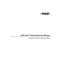
Communications Control Module Code Download
The Communications Control Module code download procedure can be
executed while the unit is operational. In addition, the user can schedule the
node reset that switches control to the new code, thus minimizing the impact
on operations. This procedure requires a dual flash image Communication
Control Module.
Note:
COM Port
FlashDLD does not support modem use. To use modems, as shown in
these figures, you must use PROCOMM PLUS or another communications
software package.
Public Switched
Telephone Network
Asynchronous
Port
PC
Units with release 4.0 or
later system software
Error-Correcting
Modems
Figure 2-1. A Communications Control Module
Code Download Configuration
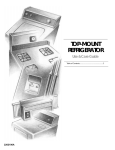
Voice Channel Code Download
Code download allows for local or remote updating of MICOM voice channel
software, when this software and its Communications Control Module
software are both at release 4.0 or later.
MICOM voice channels have one flash software bank each. Because of this
singlebankperchannel design, we do not recommend downloading code to a
voice channel while it is operational; the code download will take that
channel out of service. In addition, the singlebank design prohibits the user
from scheduling the switch to the new code.
COM Port
Public Switched
Telephone Network
Asynchronous
Port
PC
Units with release 4.0 or later
system software and voice
channel flash capability
Error-Correcting
Modems
Figure 2-2. A Voice Channel Code Download Configuration
2-4
Code Download User ’s Manual
PC-Based Code Download
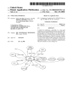
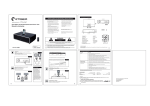
Integration Router Module Code Download
Code download allows for local or remote updating of MICOM Integration
Router Module software, when the Integration Router Module is at release
6.0 or later.
The Integration Router Module code cannot be downloaded to the Integration
Router Module while it is operational. Note also that as soon as the code
download is complete, the Integration Router Module will boot up to the new
software; the user cannot schedule the switch to the new code.
The PC must be connected (directly or using modems) to an asynchronous
port of a Communications Control Module that has a release 4.2 or later
FEATUREPAK or FlashPak (system, or Communications Control Module)
cartridge. Here are two examples of how to connect the PC:
Example A
Asynchronous
Port
COM Port
PC
(Straight Cable)
Example B
Units with release 4.1 or
later system software and
Integration Router FlashPak cartridge
Asynchronous
Port
COM Port
Public Switched
Telephone Network
PC
(Crossover Cable)
Error-Correcting Modems
(Straight
Cable)
Unit with Integration
Router to receive the
code download
Figure 2-3. Two Code Download Configurations for Integration Router Modules
2-5
Code Download User ’s Manual
PC-Based Code Download
Blank Flash EPROM and Single Flash Image Code Download
When a Communications Control Module EPROM has been completely
erased that is, when there is no software in either flash bank or in the
single flash bank of a single flash image unit code download allows for
local or remote (through modems) updating of the Communications Control
Module software.
For dual flash image units, this feature is used mainly in emergency
situations when code has been erased or is unreadable in both flash memory
banks. The only requirement is that the Communications Control Module be
connected directly to the PC that will download code to it.
For single flash image units, such as some versions of the NetRunner 75E
and Marathon 3K, this feature is the only method available for code
download.
Notes:
D
Example A below is a configuration designed for use with FlashDLD.
FlashDLD requires a direct connection between the PC and A2 or the NMS
Command Port, without the use of modems.
D
Example B, with its modem connections, shows a configuration which may
be used with another communications software package such as
PROCOMM PLUS.
Example A
COM Port
A2 or NMS Command Port
PC
(Straight Cable)
Unit
with Flash
Example B
COM Port
Public Switched
Telephone Network
A2 or NMS Command Port
PC
(Crossover Cable)
(Straight
Cable)
Error-Correcting Modems
Unit
with Flash
Figure 2-4. Two Blank Flash EPROM Code Download Configurations
(For Downloading Communications Control Module Code
to a Unit Connected Directly to a PC)
2-6
Code Download User ’s Manual
PC-Based Code Download
Step 1: Configure the Download Parameters
Overview
Before you begin to download code, you must configure the download
parameters for the $DLD download facility. This configuration can either be
done from the node's Command Facility (locally or remotely) or through
NETMan. The procedure for configuring code download parameters using
the Command Facility is described here; see the NETMan User's Manual for
information on configuring download parameters using NETMan.
The procedures outlined here are also noted in the table in Flash Status and
Control Commands" on page A1.
Procedure
Before you can perform any of these commands, you must log into the
Command Facility.
Set the $DLD Password
D
Select Configure Local Nodes ! Download Parameters !
$DLD Password.
D
Enter the password for the code download facility ($DLD) password.
(The password can have a maximum of 8 characters out of the set of
AZ and 09. It is not casesensitive.)
2-7
Code Download User ’s Manual
PC-Based Code Download
Set the Communications Control Module Bank to Activate on Reset (for
Communications Control Module Downloads Only)
When you reset using Reset ! Node: Bank Selected Software, instead of
resetting from the Communications Control Module software running in
RAM, the node resets from the flash bank you will activate in this step.
D
Select Configure Local Nodes ! Download Parameters !
Select Communications Control Module Bank to Activate.
D
Select one of the following:
-
Flash Bank 1
Flash Bank 2
Most Recent (default)
The most recent" flash bank is the bank that contains the most recently
released Communications Control Module software, as determined by the
software's date and time stamp.
Notes:
D
This procedure can also be performed at any time after software has
been downloaded if you want to switch flash software banks to load from.
D
For information on overriding this setting, refer to “Appendix C –
Overriding the Selected Flash Bank” on page C-1.
Set the $DLD Activity Timeout
You may configure the length of time the unit's $DLD download facility will
wait to disconnect if data transmission has ceased.
D
Select Configure Local Nodes ! Download Parameters ! $DLD
Activity Timeout (Seconds).
D
Specify the timeout in seconds. (The default is 120 seconds.)
Step 2a: Erase Flash Image
Overview
Before you can download code, you must erase the code in the flash bank you
will be downloading to.
Note:
2-8
In situations where invalid images are loaded in both flash banks of a
Communications Control Module FlashPak, you may erase both flash images.
The procedure is described in “Erasing Both Communications Control Module
Flash Images” on page 2-10.
Code Download User ’s Manual
PC-Based Code Download
Procedure (from the Command Facility)
1. Enter the Command Facility by entering $CMD at the ENTER
CLASS: prompt.
2. In the Communications Control Module Command Facility Main
menu, select Configure Local Nodes ! Download Parameters.
3. Select the kind of flash bank you would like to erase:
D
Note:
To erase Communications Control Module code (or
Communications Control Module code on the LAN/WAN
module):
-
Select Erase CCM Flash.
-
Select the bank you would like to erase.
D
Enter either 1 or 2 for all units except the
Marathon 3K.
D
In the case of the Marathon 3K, you will be
prompted with, ERASE ALTERNATE CCM BANK"
Select Y" to erase, N" to abort the operation.
On the Marathon 3K, when there are two flash banks, “Erase CCM Flash”
command will erase the inactive bank by default.
D
To abort, enter <CTRL>X.
To erase analog voice/fax or Digital Voice Module code:
-
Select Erase Voice Flash.
-
Select the node ID/channel number of the Flash
EPROM bank to be erased, for example:
NODEB/C2
Note:
To abort, enter <CTRL>X.
In the case of the Digital Voice Module, after flash EPROM code has been
erased, the channel indicator will be solid red, indicating that a code download
is required.
D
To erase T1 Access Module code:
-
Select Configure Local Nodes ! Erase T1/E1 Flash.
-
Enter Y to confirm the erasure of T1 Access Module
code.
During the erase procedure, the DT indicator will be solid red.
When the erase procedure is complete, the message ERASE
COMPLETED will appear, and the DT indicator will go off.
When T1 Access Module code has been erased, the T1 Access
Module's DS5 indicators will be solid red, indicating that a code
download is required.
D
On the Integration Router Module, code is erased
automatically before downloading by the DLD process.
2-9
Code Download User ’s Manual
PC-Based Code Download
Step 2b: Erasing Both Communications Control Module Flash
Memory Images
Overview
Occasionally it may be necessary to simultaneously erase both flash memory
images in FlashPaks, NetRunner 75E LAN/WAN Modules, or Marathon 3K
units in order to load software on a blank Flash EPROM. This would be
necessary, for example, if there is only one flash image loaded and the
software does not run after being moved to RAM.
Commands for this procedure are issued through:
D
The unit's LCD/Keypad, if it has one (for selected Communications
Control Module FlashPaks only), or
D
A connection to the NMS Command Port or A2 (for Communications
Control Module FlashPaks)
D
A connection to A2 (for LAN/WAN Modules or Marathon 3K units)
Voice Software
MICOM voice channel software must be erased using the procedure described
in Erase Flash Image(s)" on page 28.
Procedures
Both Communications Control Module flash images can be completely erased
simultaneously in either of the following ways:
Through the LCD/Keypad
(For 5-Slot Unit Communications Control Module FlashPaks Only)
1. Reset the unit by either:
D
Powering the unit off and then on, or
D
Simultaneously depressing the Left (z) and EXE buttons on
the unit's LCD/Keypad.
2. Depress the Up (") and Right (!) buttons on the unit's
LCD/Keypad. Do this immediately after releasing the Left (z) and
EXE buttons and continue to depress until the A4 indicator comes on.
Note:
2-10
When the A4 indicator comes on, the Communications Control Module flash
images are being erased. Once both flash images have been erased, the A4
indicator will go off and the A1 indicator will come on.
Code Download User ’s Manual
PC-Based Code Download
Through the A2 or the NMS command port
(For Communications Control Module FlashPaks or the Communications Control Module
portion of the NetRunner 75E or the Marathon 3K)
1. Set up the terminal or terminal emulation software. The proper
settings are:
D
9600 baud
D
no parity
D
8 data bits
D
1 stop bit
D
Raw ASCII (for PROCOMM PLUS)
2. Reset the unit by either:
D
Powering the unit off and then on, or
D
Simultaneously depressing the Left (z) and EXE buttons on
the unit's LCD/Keypad, if it has one.
3. Type Erase at the $DLD> prompt. The $DLD> prompt will appear
while the code is being moved to RAM, if it has one.
Note:
When the A4 indicator comes on, the Communications Control Module flash
images are being erased. Once both flash images have been erased, the A4
indicator will go off and the A1 indicator will come on.
2-11
Code Download User ’s Manual
PC-Based Code Download
Step 3: Install the FlashDLD Program
Procedures
FlashDLD, MICOM's terminal emulation software designed specifically to
perform code downloads to MICOM products, is available in two versions one for Windows and one for DOS. Both versions are included on the
FlashDLD diskette. The installation procedure for both versions of
FlashDLD software follows.
To Install FlashDLD for DOS
1. Place the FlashDLD diskette in a 3½inch floppy drive on your PC.
2. Change directories to the FlashDLD directory. For example, if you are
displaying the A drive prompt and the diskette is in drive B, you
would do the following:
a> b:
b> cd flashdld
3. Once in the FlashDLD directory, you may enter the dossetup
command.
The default source drive for dossetup is A; the default destination for
the FlashDLD files is c:\flashdld. Either or both of these file locations
can be changed using command line arguments in this format:
dossetup [source [destination]]
The following examples illustrate the use of dossetup command line
arguments to change the source drive and destination directory.
dossetup Examples
Command
2-12
Result
dossetup b d:\flashdld.dos
Dossetup will look in the B drive
for the files and load them on the
D drive in the flashdld.dos
directory.
dossetup b
Dossetup will look in the B drive
for the files and load them on the
C drive in the flashdld directory
(the default).
dossetup a d:\flashdld.dos
Dossetup will look in the A drive
(the default) for the files and load
them on the D drive in the
flashdld.dos directory.
Code Download User ’s Manual
PC-Based Code Download
To Install FlashDLD for Windows
1. Place the FlashDLD diskette in a 3½inch floppy drive on your PC.
2. Run the winsetup.exe file. From the Windows Program Manager, select
File ! Run. In the Command Line box, type the file location of the
winsetup.exe file (\flashdld\winsetup.exe) preceded by the drive letter
of the drive where the FlashDLD diskette is located and a colon. For
example, if your FlashDLD diskette is in drive A, type:
a:\flashdld\winsetup.exe
3. Select OK.
4. When the Setup" screen appears, select Continue to begin the
loading of FlashDLD.
5. In the Destination Path" screen, select the name of the destination
directory. (The default is C:\FlashDLD; if necessary, change the
name.) Select Continue.
6. In the Option Selection" click on deselect either FlashDLD
Executables" or Flash Download Files" if you do not want to install
them. (You will need the FlashDLD Executables to run MICOM's
FlashDLD software. The Flash Download Files are the files you will
be downloading to your unit.) Click on Continue.
7. The default Windows program group for the FlashDLD executables is
FlashDLD". If you would like to, you may change the name of the
program group in the Destination Group" screen. Select Continue
when the box contains the name of the program group where you
would like the FlashDLD executables to be displayed as Windows
icons.
8. The FlashDLD setup program will install the FlashDLD software.
2-13
Code Download User ’s Manual
PC-Based Code Download
Step 4: Configure FlashDLD
Overview
FlashDLD, MICOM's terminal emulation software, is designed specifically to
perform code downloads to MICOM products at release 4.0 or later. (The
Integration Router Module requires release 6.0 of Integration Router
software and release 4.2 of MICOM System Software.)
The following are the procedures for configuring FlashDLD for code
download. FlashDLD is supplied in two versions, one for Windows and one
for DOS. The configuration of both versions is described below. If you are
using MICOM's FlashDLD software to perform a code download you will need
this procedure as well as the one described in How to Download Code" below.
Note:
If you are using a communications software package other than FlashDLD
remember that these procedures describe specific menu choices for use with
MICOM’s FlashDLD software. While the download parameters will be set to the
same values no matter what communications software package you are using,
other software packages, such as PROCOMM PLUS, will have their own
configuration procedures. Refer to the your software’s documentation for
information on its use.
Configuration Settings
Whether you use FlashDLD or PROCOMM PLUS, you must configure your
communications software (and any modems) as follows:
Communications Software
8-bit
Remote Modem Attached to Unit
8-bit
No parity
No parity
Software flow control (XON/XOFF)
Software flow control (XON/XOFF)
Transparent (or Raw) ASCII or Binary
No echo
The baud rate must be equal to that of the
unit’s port.
No result codes
Dial up mode
Asynchronous mode
DCD follows remote carrier
2-14
Code Download User ’s Manual
PC-Based Code Download
To Configure FlashDLD for DOS
1. Type the command to run FlashDLD for DOS:
c:\flashdld> flashdos.exe
2. Type <Alt>S to enter setup mode.
3. Use the space bar to toggle between configuration parameter choices.
Use the arrow keys to move down the list. When you are done, the
screen should look something like this:
Change Configuration
Use <SPACE BAR> to toggle item
Use <ESC> to exit setup
Parameter | Setup
–––––––––––––––––––––––
COM Port | COM1
Baud Rate | 9600
Word Size | 8
Parity
| None
Stop Bits | 1
The COM Port may be configured for either COM1 or COM2,
depending on your setup.
4. Once the configuration is correct, exit the setup mode. Type <ESC>.
5. When asked Save this configuration?", answer Y.
FlashDLD for DOS Commands
The commands available within the FlashDLD program for DOS are
indicated in the table below.
Keystroke
Function
<Alt>E
Exits the program
<Alt>B
Performs a one-second break
<Alt>C
Clears local screens and resets the terminal emulator
<Alt>S
Enters the setup mode
<Alt>F
Enters the file send mode
<Esc>
Accepts configuration or aborts download in progress
2-15
Code Download User ’s Manual
PC-Based Code Download
To Configure FlashDLD for Windows
1. Doubleclick on the FlashDLD for Windows icon.
2. Select Configuration from the main menu.
3. Set the COM options as follows:
Note:
2-16
COM Option
Setting
Port
COM1, COM2, COM3, or COM4 (as appropriate for your
installation)
Baud Rate
9600
Data Bits
8
Parity
None
Stop Bits
1
With the exception of the port option (COM1, etc.), these are the default
settings. The default port is COM1.
Code Download User ’s Manual
PC-Based Code Download
Step 5a: Communication Control Module Code Download
Overview
Any Communications Control Module dualflash image EPROM at release
4.0 or later at may have code downloaded to it as an async data stream from
any point in the network.
The following procedure is for downloading MICOM software from a PC using
a communications package (such as PROCOMM PLUS or MICOM's
FlashDLD terminal emulation software) and connected to any async channel
in the MICOM network. This procedure allows for the downloading of
software to operational units.
Notes:
D
During a code download, the network acts as a data pipe and does not
look at the contents of the transferred file. Only the destination download
facility interprets the download file (which may be considerably different for
the different devices).
D
MICOM’s FlashDLD program is designed only for downloading
software to Flash EPROM on MICOM products. No other uses for
FlashDLD are supported.
When to Use
Use this procedure for all Communications Control Module code downloads
except those to:
-
Completely erased Communications Control Module Flash EPROMs
-
Singleflash image EPROMs, such as those on some NetRunner 75E
and Marathon 3K units
Note:
To download code to completely erased Communications Control Modules or
Flash EPROMs, use Step 5d, the “Communications Control Module Blank
Flash EPROM Code Download” procedure, on page 2-30).
Before you perform this procedure, you should have already have performed
the following steps:
1. Configure the download parameters
2a. Erase the flash bank to which you will be downloading code
3. Install FlashDLD (or another communications software package)
4. Configure FlashDLD (or another communications software package)
2-17
Code Download User ’s Manual
PC-Based Code Download
Procedure: Communications Control Module Code Download
1. Configure modems. For modems attached directly to units, issue the
following command string to the modem through an ASCII terminal:
AT&FE0Q1S0=2&C1&D0&W
followed by a carriage return. This command sets up the modem for
communication. For more information on modem setup, refer to the
Network Management System Module User's Manual.
2. Enter terminal emulation mode. In FlashDLD, configuring the
FlashDLD parameters and clicking OK" will bring up a terminal
emulation window if FlashDLD and the port on your unit are
configured correctly.
3. Type <return> to get to the ENTER CLASS: prompt.
4. Connect to the download facility ($DLD) of the unit as follows.
Note:
Before the destination download facility ($DLD) will accept a connection, the
flash bank must have been previously erased. In the case of Communications
Control Module FlashPaks and the Communications Control Module portion of
LAN/WAN Modules, which have two flash banks, only one flash bank should be
erased. See “Flash Status and Control Commands” on page A-1 for
information on displaying the status of flash banks.
Action
Response
Summary
ENTER PASSWORD:
Connect to the unit’s download facility at the ENTER
CLASS: prompt. The command will have the
following format:
ENTER CLASS: node_ID/$DLD
where D node_ID is the name of the node
D $DLD is the download facility command
Example
To connect to the download facility of a
Communications Control Module in a node named
node1:
node1/$DLD
Enter the correct download password.
[ CALL IN PROGRESS ]*
CONNECTED
* If connecting to a remote unit, you will see this message.
5. Switch to file transfer mode and send the download file. The
download facility will disconnect when the download is complete.
D
For FlashDLD for DOS, enter AltF to enter the file transfer
mode. Then, select the file to download.
D
For FlashDLD for Windows, select File ! Send to enter the
file transfer mode. Highlight the file to download, and click on
OK.
The following messages should appear:
DOWNLOAD COMPLETE
DISCONNECTED
2-18
Code Download User ’s Manual
PC-Based Code Download
In addition, the following error messages may appear on your
terminal during download.
Unit Message, or Summary
INVALID DOWNLOAD FILE!!
FLASH WRITE ERROR!!
DOWNLOAD FILE CHECKSUM ERROR!!
WRONG HARDWARE PLATFORM!!
Notes:
D
If any of the above errors are detected during download, the bank will
be erased and you will need to attempt the code download again.
D
Each download facility has an activity timer. If no data is received for a
specified interval, the connection will be broken, and the flash bank written
to during the attempted download will be erased. (The default activity
timeout is 120 seconds. Refer to “Set the $DLD Activity Timeout” on page
2-8 for details on configuring the activity timeout.)
D
If the connection to the $DLD Download Facility is broken before the
“Download Complete” message is received, the bank will be erased.
D
If the FlashDLD window fills up with data, the download has been
unsuccessful and the FlashDLD software may need to be reinitialized. Quit
FlashDLD and start it up again to reinitialize it.
D
Once you have connected to the $DLD facility, you must not type
anything into the computer. The $DLD facility will try to interpret anything
typed in at this point as downloaded code.
6. Verify the success of the download procedure by accessing the
destination node's Command Facility and checking the contents of the
flash bank(s) in question.
Under the Main menu, select Status and Statistics ! PROM ID.
This will display information on both Communications Control Module
flash memory banks and their latest revision loaded into CMOS. (For
more information on flash commands, refer to Flash Status and
Control Commands" on page A1).
2-19
Code Download User ’s Manual
PC-Based Code Download
Step 5b: Voice Channel Code Download
Overview
MICOM analog voice/fax and Digital Voice Modules can have code down
loaded to them according to the following guidelines:
D
The Universal Voice/Fax Module (containing a Flash EPROM at
release 4.0 or later software and installed in a unit that is also at
release 4.0 or later)
D
Digital Voice Modules at release 4.3 or later (and installed in a unit
that is also at release 4.3 or later). These include Digital Voice
Modules on
-
T1 Access Modules
-
E1 Access Modules
-
Digital Voice Expansion Modules
The code is downloaded as an async data stream from any point in the
network.
The following procedure is for downloading MICOM voice software from a PC
using a communications package (such as PROCOMM PLUS or MICOM's
FlashDLD terminal emulation software) and connected to any async channel
in the MICOM network. This download procedure does not allow for
downloading software to voice channels in operation.
Notes:
D
During a code download, the network acts as a data pipe and does not
look at the contents of the transferred file. Only the destination download
facility interprets the download file (which may be considerably different for
the different devices).
D
MICOM’s FlashDLD program is designed only for downloading
software to Flash EPROM on MICOM products. No other uses for
FlashDLD are supported.
D
For information on installing Flash EPROMs in Universal Voice/Fax
Modules released prior to release 4.0, refer to the manual “Universal
Fax/Voice Module Flash EPROM Field Upgrade Kit Installation Instructions”
(part number, 800-1849-40).
When to Use
Before you perform this procedure, you should have already performed the
following steps:
1. Configure the download parameters
2a. Erase the flash image on the voice channel to which you will be
downloading code
3. Install FlashDLD (or another communications software package)
4. Configure FlashDLD (or another communications software package)
2-20
Code Download User ’s Manual
PC-Based Code Download
Procedure: Voice Channel Code Download
1. Configure modems. For modems attached directly to units, issue the
following command string to the modem through an ASCII terminal:
AT&FE0Q1S0=2&C1&D0&W
Then press <Enter>. This command sets up the modem for
communication. For more information on modem setup, refer to the
Network Management System Module User's Manual.
2. Enter terminal emulation mode. In FlashDLD, configuring the
FlashDLD parameters and clicking OK" will bring up a terminal
emulation window if FlashDLD and the port on your unit are
configured correctly.
3. Type <return> to get to the ENTER CLASS: prompt.
4. Connect to the download facility ($DLD) of the unit as follows.
Note:
Before the destination download facility ($DLD) will accept a connection,
the flash EPROM must have been previously erased. See the “Flash Status
and Control” section on page A-1 for information on displaying the status of
flash banks.
Action
Summary
Response
ENTER PASSWORD:
Connect to the voice channel’s download facility at
the ENTER CLASS: prompt. The command will
have the following format:
ENTER CLASS: node_ID/channel/$DLD
where D
D
D
node_ID is the name of the node
channel is the channel number
$DLD is the download facility command
Example
To connect to the download facility of a voice channel installed in location D1 on a node named node1:
node1/D1/$DLD
Enter the correct download password.
[ CALL IN PROGRESS ]*
CONNECTED
* If connecting to a remote unit, you will see this message.
2-21
Code Download User ’s Manual
PC-Based Code Download
5. Switch to file transfer mode and send the download file. The
download facility will disconnect when the download is complete.
D
For FlashDLD for DOS, enter AltF to enter the file transfer
mode. Then, select the file to download.
D
For FlashDLD for Windows, select File ! Send to enter the
file transfer mode. Highlight the file to download, and click on
OK.
The following status messages should appear:
DOWNLOAD COMPLETE
DISCONNECTED
In addition, the following error messages may appear on your terminal
during download:
Messages
INVALID DOWNLOAD FILE!!
FLASH WRITE ERROR!!
DOWNLOAD FILE CHECKSUM ERROR!!
Notes:
D
If you get an error message indicating that the software was not
received well at the channel (such as “FLASH WRITE ERROR!!”), erase
the software again and re-attempt the code download.
D
If the FlashDLD window fills up with data, the download has been
unsuccessful and the FlashDLD software may need to be reinitialized. Quit
FlashDLD and start it up again to reinitialize it.
D
Each download facility has an activity timer. If no data is received for a
specified interval, the connection will be broken, and the flash EPROM
written to during the attempted download will be erased. (The default
activity timeout is 120 seconds. Refer to “Set the $DLD Activity Timeout”
on page 2-8 for details on configuring the activity timeout.)
D
Once you have connected to the $DLD facility, you must not type
anything into the computer. The $DLD facility will try to interpret anything
typed in at this point as downloaded code.
6. Verify the success of the download procedure by accessing the
destination node's Command Facility and checking the contents of the
flash EPROM(s) in question.
Under the Main menu, select Status and Statistics ! Voice/Fax
Status. This will PROM number and revision of the software in the
flash EPROM. (For more information on flash commands, refer to
Flash Status and Control Commands" on page A1).
2-22
Code Download User ’s Manual
PC-Based Code Download
Step 5c: T1 Access Module Code Download
Overview
Any MICOM T1 Access Module may have code downloaded to it as an async
data stream from any point in the network.
The following procedure is for downloading MICOM T1 Access Module
software from a PC using a communications package (such as PROCOMM
PLUS or MICOM's FlashDLD terminal emulation software) and connected to
any async channel in the MICOM network. This download procedure does
not allow for downloading software to T1 Access Modules in operation.
Notes:
D
During a code download, the network acts as a data pipe and does not
look at the contents of the transferred file. Only the destination download
facility interprets the download file (which may be considerably different for
the different devices).
D
MICOM’s FlashDLD program is designed only for downloading
software to Flash EPROM on MICOM products. No other uses for
FlashDLD are supported.
D
T1 Access Module code download requires MICOM System Software
release 4.3 or later.
When to Use
Before you perform this procedure, you should have already performed the
following steps:
1. Configure the download parameters
2a. Erase the flash image on the T1 Access Module to which you will be
downloading code
3. Install FlashDLD (or another communications software package)
4. Configure FlashDLD (or another communications software package)
Procedure: T1 Access Module Code Download
1. Configure modems. For modems attached directly to units, issue the
following command string to the modem through an ASCII terminal:
AT&FE0Q1S0=2&C1&D0&W
Then press <Enter>. This command sets up the modem for
communication. For more information on modem setup, refer to the
Network Management System Module User's Manual.
2. Enter terminal emulation mode. In FlashDLD, configuring the
FlashDLD parameters and clicking OK" will bring up a terminal
emulation window if FlashDLD and the port on your unit are
configured correctly.
2-23
Code Download User ’s Manual
PC-Based Code Download
3. Type <return> to get to the ENTER CLASS: prompt.
4. Connect to the download facility ($DLD) of the unit as follows.
Note:
Before the destination download facility ($DLD) will accept a connection,
the flash bank must have been previously erased. See the “Flash Status and
Control” section on page A-1 for information on displaying the status of flash
banks.
Action
Response
Summary
ENTER PASSWORD:
Connect to the T1 Access Module’s download facility at the ENTER CLASS: prompt. The command
will have the following format:
ENTER CLASS: node_ID/TAM/$DLD
where D
D
D
node_ID is the name of the node
TAM is the T1 Access Module’s channel
number
$DLD is the download facility command
Examples
To connect to the download facility of the T1 Access
Module installed in a node named node1:
node1/TAM/$DLD
Enter the correct download password.
[ CALL IN PROGRESS ]*
CONNECTED
* If connecting to a remote unit, you will see this message.
5. Switch to file transfer mode and send the download file. The
download facility will disconnect when the download is complete.
D
For FlashDLD for DOS, enter AltF to enter the file transfer
mode. Then, select the file to download.
D
For FlashDLD for Windows, select File ! Send to enter the
file transfer mode. Highlight the file to download, and click on
OK.
The following messages may appear on your terminal during
download:
Unit Message
INVALID DOWNLOAD FILE!!
FLASH WRITE ERROR!!
DOWNLOAD FILE CHECKSUM ERROR!!
DOWNLOAD COMPLETE
2-24
Code Download User ’s Manual
PC-Based Code Download
In addition, the following messages may appear if you try to access the
T1 Access Module after its code has been erased but before new code
has been downloaded to it.
Unit Message or Indicator
Notes:
Explanation
T1/E1 INVALID FLASH, PLEASE
DOWNLOAD!!
If you try to access the T1 Access Module
after its operational code has been erased,
this message reminds you to perform a
code download.
T1/E1 CODE DOWNLOAD IS IN
PROGRESS, PLEASE TRY LATER!!
If you try to reset the T1 Access Module
from the Command Facility while a code
download is in progress, this message will
explain why the reset is unsuccessful.
DS5 — Solid Red
Code download required.
DS1 — Flashing Green
Code download in progress.
DS1 — Solid Green
Operational.
D
If you get an error message indicating that the software was not
received well at the channel (such as “FLASH WRITE ERROR!!”), erase
the software again and re-attempt the code download.
D
If the FlashDLD window fills up with data, the download has been
unsuccessful and the FlashDLD software may need to be reinitialized. Quit
FlashDLD and start it up again to reinitialize it.
D
Each download facility has an activity timer. If no data is received for a
specified interval, the connection will be broken, and the flash bank written
to during the attempted download will be erased. (The default activity
timeout is 120 seconds. Refer to “Set the $DLD Activity Timeout” on page
2-8 for details on configuring the activity timeout.)
D
The T1 Access Module code download may take longer than other
MICOM code downloads. Be sure to wait for the DISCONNECTED
message, otherwise you might abort the code download.
6. Verify the success of the download procedure. If the DS1
indicator is solid green, the code download has been successful. You
may further verify this by accessing the destination node's T1/E1 user
interface from the Command Facility. If you can access this interface,
the code download has been successful.
2-25
Code Download User ’s Manual
PC-Based Code Download
Step 5d: Integration Router Module Code Download
Overview
Any Integration Router Module at release 6.0 or later that is installed in a
unit with Communications Control Module software at release 4.2 or later
may have code downloaded to it as an async data stream from any point in
the WAN.
Besides the procedures outlined here, the Integration Router Module can also
have code downloaded to it from NETMan or by using Bootp or TFTP. For
information on code downloads to the Integration Router Module using
NETMan, refer to the NETMan User's Manual; for information on code
downloads to the Integration Router Module using Bootp or TFTP, refer to
LANBased Code Download" in section 3 of this manual or to the Integration
Router User's Manual.
The following procedure is for downloading MICOM Integration Router
Module software from a PC using a communications package (such as
PROCOMM PLUS or MICOM's FlashDLD terminal emulation software) and
connected to any async channel in the MICOM network. This download
procedure does not allow for downloading software to an operational
Integration Router Module.
Notes:
D
During a code download, the network acts as a data pipe and does not
look at the contents of the transferred file. Only the destination download
facility interprets the download file (which may be considerably different for
the different devices).
D
MICOM’s FlashDLD program is designed only for downloading
software to Flash EPROM on MICOM products. No other uses for
FlashDLD are supported.
When to Use
Before you perform this procedure, you should have already performed the
following steps:
1. Configure the download parameters
3. Install FlashDLD (or another communications software package)
4. Configure FlashDLD (or another communications software package)
2-26
Code Download User ’s Manual
PC-Based Code Download
Procedure: Integration Router Module Code Download
1. Connect to the Command Facility ($CMD) of the unit whose
Integration Router Module is to receive the code download:
Action
Response
Summary
Connect to the unit’s Command Facility at the
ENTER CLASS: prompt. The command will have
the following format:
ENTER CLASS PASSWORD:
ENTER CLASS: node_ID/$CMD
where D node_ID is the name of the unit whose
Integration Router Module is to receive
the code download
D $CMD is the Command Facility
command
Example
To connect to the Command Facility of a node
named node1:
ENTER CLASS: node1/$CMD
Enter the correct password.
[ CALL IN PROGRESS ]*
CONNECTED
* If connecting to a remote unit, you will see this message.
2. Reset the Integration Router Module. From the Command
Facility Main Menu, select Reset ! Integral LAN.
3. Specify the location containing the Integration Router Module
(usually slot B) at the ENTER MODULE LOCATION prompt. In this
example, we will use module location B:
ENTER MODULE LOCATION [B–E] (^X TO ABORT):b
4. Place the Integration Router Module in code download mode.
From the Integral LAN Reset Menu select Code Download: WAN to
LAN.
Displayed on the screen you will see a message sequence similar to the
following:
21:23:32
21:24:02
21:24:04
21:24:10
TPNET
TPNET
TPNET
TPNET
[B]
{B}
[B]
[B]
LAN RESET: WAN–>LAN RELOAD
LAN MODULE UP
Boot 144–0153–0A
CCM load waiting:
! WARNING
You must see the CCM load waiting: message displayed
before proceeding to the next step. Once this message
appears, the Integration Router Module is in the download
mode and ready for data.
2-27
Code Download User ’s Manual
PC-Based Code Download
5. Exit the Command Facility. Select Exit Command Facility from
the Command Facility Main Menu.
If the PC is connected to an intermediate unit (i.e., not physically
connected to the unit whose Integration Router Module is being
downloaded), then exit from that unit's Command Facility Main
Menu, as well.
6. Connect to the download facility ($DLD) of the Integration Router
Module that is having code downloaded to it.
Action
Summary
Connect to the Integration Router Module’s
download facility at the ENTER CLASS: prompt.
The command will have the following format:
Response
ENTER PASSWORD:
ENTER CLASS: node_ID/lan_slot/$DLD
where D
D
D
node_ID is the name of the node
lan_slot is the letters “LAN” followed by
the module location of the Integration
Router Module (usually B). (Note that
the default class name for the Integration
Router Module can be changed. If it has
been changed, you must use this new
default class name.)
$DLD is the download facility command
Example
To connect to the download facility of an Integration
Router located in module location B of a node
named node1:
node1/lanb/$DLD
Enter the correct download password.
[ CALL IN PROGRESS ]*
CONNECTED
* If connecting to a remote unit, you will see this message.
Note:
2-28
If you do not receive a “Call In Progress” message followed by a “Connected”
message, the Integration Router Module may not be ready for the download.
Wait a few seconds, then try again.
Code Download User ’s Manual
PC-Based Code Download
7. Send the code download file to the Integration Router Module
using the ASCII file transfer mode of the PC program.
D
For FlashDLD for DOS, enter AltF to enter the file transfer
mode. Then, select the file to download.
D
For FlashDLD for Windows, select File ! Send to enter the
file transfer mode. Highlight the file to download, and click on
OK.
During the download, the Integration Router Module will cause
various messages to be displayed on the LCD (if there is one) and on a
$CMD terminal (if connected). On the $CMD terminal, a normal code
download will cause the following message sequence (where TPNET is
the name of the node):
00:00:25 TPNET [B] $DLD Connected
CONNECTED TPNET/B01 TPNET/A05
00:00:45 TPNET [B] Erasing Flash...
00:05:07 TPNET [B] Done
00:05:32 TPNET [B] CCM downloading...
00:14:37 TPNET [B] CCM load success.
DISCONNECTED TPNET/B01 TPNET/A05
00:14:41 TPNET [B] Adding checksums..
00:15:21 TPNET [B] LAN RESET: VIA LAN MODULE
00:15:45 TPNET [B] LAN MODULE UP
Once the download is successful and the new software stored in the
LAN FlashPak, the Integration Router Module will reset and start
executing the new software.
Notes:
D
If you get an error message indicating that the software was not
received well at the channel (such as “FLASH WRITE ERROR!!”), erase
the software again and re-attempt the code download.
D
If the FlashDLD window fills up with data, the download has been
unsuccessful and the FlashDLD software may need to be reinitialized. Quit
FlashDLD and start it up again to reinitialize it.
D
Each download facility has an activity timer. If no data is received for a
specified interval, the connection will be broken, and the flash EPROM
written to during the attempted download will be erased. (The default
activity timeout is 120 seconds. Refer to “Set the $DLD Activity Timeout”
on page 2-8 for details on configuring the activity timeout.)
D
Once you have connected to the $DLD facility, you must not type
anything into the computer. The $DLD facility will try to interpret anything
typed in at this point as downloaded code.
2-29
Code Download User ’s Manual
PC-Based Code Download
Step 5e: Blank Flash EPROM and Single Flash Image Code Download
Overview
In addition to the code download procedures outlined above, Communications
Control Module Flash EPROMs at release 4.0 or later with dual flash image
capabilities can have code downloaded to them even if there is no code in
flash memory. They contain a boot PROM which allows for code downloads
(from a PC connected either locally or through modems to the A2 or NMS
Command Port).
This blank Flash EPROM code download procedure also allows for
downloading code to single flash image units, such as some NetRunner 75E
and Marathon 3K units.
The boot PROM moves the operational code from the Flash EPROM to static
RAM, then transfers control to that code. (For a description of this process,
refer to Appendix B The Boot PROM Startup Process" on page B1.)
During this procedure, the Communications Control Module image is written
to both flash banks of a dual bank FlashPak.
Notes:
D
FlashDLD, MICOM’s terminal emulation program is designed only for
downloading software to Flash EPROMs on MICOM products. No other
uses for the terminal emulation software are supported.
D
The following procedure assumes that both banks of the flash EPROM
have already been erased. See “Erasing Both Communications Control
Module Flash Memory Images” (page 2-10) for information on erasing both
Communications Control Module or LAN/WAN Module flash images.
When to Use
Use this procedure only when:
D
Both flash images of Communications Control Module software have
been erased or contain corrupted code.
D
Downloading code to a singleflash image Communications Control
Module, such as on some NetRunner 75E and Marathon 3K units.
Perform code downloads other than those described above using the
Communications Control Module Code Download" procedure (page 217).
2-30
Code Download User ’s Manual
PC-Based Code Download
Procedure: Communications Control Module Blank Flash EPROM Code Download
1. Configure the PC communication package to be identical to the
factory configuration of port A2, according to the following table:
Communications Software
8-bit
No parity
Software flow control (XON/XOFF)
Transparent (or Raw) ASCII or Binary
9600 baud
Note:
Remote Modem Attached to Unit
8-bit
No parity
Software flow control (XON/XOFF)
No echo
No result codes
Dial up mode (Auto-Answer)
Asynchronous mode
Follow remote carrier
Any interconnect or synchronous links existing at the A2 port must be
disconnected.
2. Set the communication package to run in terminal emulation
mode.
3. Attach the PC to A2 or the NMS Command Port with an
appropriate straightthrough cable.
4. Reset the unit. Either:
D
D
Power the unit off and then on, or
Simultaneously depress the Left (z) and EXE buttons on the
unit's LCD/Keypad, if it has one. Hold these buttons down for
3 seconds.
The indicators will show the startup status as described in the
Startup and Operation" section of your User's Manual.
Note:
When the A1 indicator is on solid and the Integration unit issues the message
START DOWNLOAD, the unit is ready to receive the download.
2-31
Code Download User ’s Manual
PC-Based Code Download
5. Switch the communication package to file transfer mode and
send the download file. The A1 light will blink during the file
transfer. The indicator message code patterns for normal code
downloads are as follows:
Indicators
Style
Unit Message, or Summary
A1
Solid
START DOWNLOAD
A1
Blinking
TRANSFER GOING ON
All but A1
Solid
DOWNLOAD COMPLETE
If there are any errors during the download, the unit will issue one of
the following messages:
Note:
Indicators
Messages
A2+A1
FLASH WRITE ERROR!! or
WRONG HARDWARE PLATFORM!!
A3+A2+A1
INVALID DOWNLOAD FILE!!
A4+A3+A2+A1
DOWNLOAD FILE CHECKSUM ERROR!!
The flash image written to during the attempted download will be erased after
the next reset if an error occurs during download.
6. When the transfer is complete, the unit will issue the message
Input file received. Reset." All indicators except A1 should be
on. The unit will reset automatically after approximately 30 seconds.
It will come up running the newly downloaded software.
2-32
LAN-Based Code Download
3
Overview
The Integration Router Module can download its operating software from a
server running Bootp and TFTP, or TFTP only. Bootp and TFTP download is
enabled by default. You must turn off Bootp in order to perform a TFTP only
download.
Bootp and TFTP are TCP/IP protocols. To perform a code download using
these protocols requires some setup on the server. As server configurations
vary extensively, the following procedures are only approximate examples. To
accomplish this form of code download, you must be experienced in TCP/IP
LAN administration. If you are unsure of how to set up a server to transfer
files using Bootp/TFTP, you should perform the code download using a PC
connected to a unit on the WAN.
IMPORTANT:
The server to be used for downloading the Integration Router software must be on the
same LAN segment (same network number) as the Integration Router itself. You cannot
perform the download from:
D
A server on a LAN segment that is located across the WAN from the Integration
Router
D
A LAN segment with a different network number that is accessed using a router
Code Download Using Bootp/TFTP
Overview
The procedure for performing a code download using both Bootp and TFTP
involves four steps:
1. Note the Integration Router Module's Hardware Address
2. Set up the Bootp Server
3. Set up the TFTP Server
4. Initiate the Code Download
Additionally, if it is necessary to restart a Bootp/TFTP code download, you
must perform:
5. Restart the Bootp/TFTP Code Download
Note:
The following procedure describes a Sun workstation running SunOS 4.1.3 as
the Bootp/TFTP server. Configuring other machine types to be Bootp/TFTP
servers may differ in the details, but the essential steps are basically the same.
3-1
Code Download User ’s Manual
LAN-Based Code Download
Step 1: Note the Integration Router Module’s Hardware Address
For future reference, make a note of the Integration Router Module's
hardware address (Ethernet address) using the following procedure:
1. Connect to class node_ID/$CMD (where node_ID is the name of the
unit whose Integration Router Module is to receive the code
download). In this example, we will connect to the $CMD facility on
the remote node named tpnet:
ENTER CLASS: tpnet/$cmd
PASSWORD
Note:
The local node requires only $cmd be entered at the ENTER CLASS: prompt.
The Command Facility Main Menu should be displayed on your
terminal.
2. Select INTEGRAL LAN LOCAL MODE ACCESS from the Command
Facility Main Menu.
3. Specify the slot containing the Integration Router at the ENTER
MODULE LOCATION prompt. In this example, we will use module
location B:
ENTER MODULE LOCATION [B–E] (^X TO ABORT):b
4. At the Enter username> prompt, enter a user name:
Enter username> Dave
Local>
5. Enter the following command:
Local> SHOW SERVER
6. Copy down the hardware address displayed on the screen.
7. Log out of the Integration Router Module's command line interface:
Local> LOGOUT
8. Exit the Command Facility. Select EXIT Command Facility from the
Command Facility Main Menu.
If the PC is connected to an intermediate unit (i.e., not physically
connected to the unit whose Integration Router Module is being
downloaded), then exit from that unit's Command Facility Main
Menu, as well.
3-2
Code Download User ’s Manual
LAN-Based Code Download
Step 2: Set Up the Bootp Server
You will need to set up the Bootp server that resides on the download host
system. This usually involves the following:
1. Create (or modify) a configuration file that contains information
about the devices Bootp is to respond to. This configuration file
contains a minimum of the following parameters for each device:
D
D
D
D
Hardware (Ethernet) address of the device
IP address of the device
Network name of the device
Name of the file to download to the device
-
22380A00.IRM
-
22390A00.IRM
for Marathon and STADIA Integration
Hub units
for NetRunner units
Here is a sample file used in Sun workstations, called /etc/bootptab:
micom:ht=1:ha=0040c5010101:ip=199.30.19.214:hd=/tftpboot:bf=22390A00.IRM:
micom:ht=1:ha=0040c5100c3f:ip=199.30.19.215:hd=/tftpboot:bf=22390A00.IRM
File to download
Directory for download file
Device's IP address in decimal
Device's hardware address in hexadecimal
Device's hardware type (Integration Router Module = 1)
Network name of the device
2. Start the Bootp server process. This may be a specific server
process always running on the download host system, or, the server
process may be invoked on an as needed basis (as in the case of Sun
workstations). Here is the line for Sun workstations in the
/etc/inetd.conf file for starting a Bootp server process:
bootps
dgram
udp
Protocol
Socket type
Service name
wait
root
User
Wait status
/etc/bootpd
Server program
bootpd
Arguments
Once the necessary information is included in the /etc/inetd.conf file,
the inetd process is signaled to read the inet.conf file. (Normally, inetd
reads the file during server bootup.)
3-3
Code Download User ’s Manual
LAN-Based Code Download
Step 3: Set Up the TFTP Server
You will need to set up the TFTP server that resides on the download host
system. This involves two steps.
1. Copy the appropriate .IRM file from the LAN FlashPak Code
Download Software diskette to the TFTP directory:
NetRunner:
Marathon/STADIA:
22390A00.IRM
22380A00.IRM
For Sun workstations, the default TFTP directory is /tftpboot.
Make sure the TFTP directory and the download file have owner,
group, and world read permissions. For example:
<root>troll:/> cd /tftpboot
<root>troll:/tftpboot> ls –l
total 2339
drwxrwxrwx 3 root
512 Mar 28 12:51 ./
drwxr–xr–x 21 root
1024 Mar 29 09:03 ../
–rw–rw–r–– 1 root
519128 Mar 28 15:27 22390A00.IRM
Owner Read
Group Read
World Read
The .IRM files are in binary format. You must use the binary mode
when transferring these files from the diskette to the download host
system.
2. Start the TFTP server process. This may be a specific server
process always running on the download host system, or the server
process maybe invoked on an as needed basis (as in the case of Sun
workstations). Here is the line for Sun workstations in the
/etc/inetd.conf file for starting a TFTP server process:
tftp
dgram
udp
Protocol
Socket type
Service name
3-4
wait
root
Wait status
User
/usr/etc/in.tftpd
Server program
in.tftpd –s /tftpboot
Arguments
Code Download User ’s Manual
LAN-Based Code Download
Once the necessary information is included in the /etc/inetd.conf file,
the inetd process is signaled to read the inetd.conf file.
Since the -s option (for security) is appended to the in.tftpd argument
in the tftp line of the /etc/inetd.conf example above, the TFTP daemon
will require the directory to match that specified in the line (/tftpboot).
In this case, the /tftpboot directory is expected to be a subdirectory
under the default TFTP directory. Thus, it is necessary to create a
subdirectory called tftpboot under the /tftpboot directory and set up a
link in that subdirectory to the download file in the parent directory.
For example:
<root>troll:/> cd /tftpboot
<root>troll:/tftpboot> ls –l
total 2339
drwxrwxrwx 3 root
512 Mar 28
drwxr–xr–x 21 root
1024 Mar 29
–rw–rw–r–– 1 root
519128 Mar 28
drwxrwxr–x 2 root
512 Mar 22
<root>troll:/tftpboot> cd tftpboot
<root>troll:/tftpboot/tftpboot> ls –l
total 6
drwxrwxr–x 2 root
512 Mar 22
drwxrwxrwx 3 root
512 Mar 28
lrwxrwxrwx 1 root
11 Mar 22
<root>troll:/tftpboot/tftpboot>
12:51
09:03
15:27
15:42
./
../
22390A00.IRM
tftpboot/
15:42 ./
12:51 ../
15:42 22390A00.IRM –> ../22390A00.IRM
3-5
Code Download User ’s Manual
LAN-Based Code Download
Step 4: Initiate the Code Download Using Bootp/TFTP
1. Connect to class node_ID/$CMD (where node_ID is the name of the
unit whose Integration Router Module is to receive the code
download). In this example, we will connect to the $CMD facility on
the remote node named tpnet:
ENTER CLASS: tpnet/$cmd
ENTER CLASS PASSWORD
Note:
The local node requires only $cmd be entered at the ENTER CLASS: prompt.
2. Select Reset !Integral LAN from the Command Facility Main Menu.
3. Specify the module location containing the Integration Router Module
at the ENTER MODULE LOCATION prompt. In this example, we will
use module location B:
ENTER MODULE LOCATION [B–E] (^X TO ABORT):b
4. Select Code Download: LAN to LAN from the Integral LAN Reset
Menu.
The Integration Router Module will reset and broadcast a Bootp
request to the LAN. It is up to the Bootp server to respond to the
Integration Router Module's Bootp request and initiate the code
download.
During the download, the Integration Router Module will cause
various messages to be displayed on the LCD (if there is one) and on a
$CMD terminal (if connected). On the $CMD terminal, a normal code
download will cause the following message sequence (where TPNET is
the node name):
00:05:12
00:05:21
00:05:23
00:05:32
00:05:40
00:10:22
00:10:40
00:10:55
00:12:06
00:12:20
TPNET
TPNET
TPNET
TPNET
TPNET
TPNET
TPNET
TPNET
TPNET
TPNET
[B]
[B]
[B]
[B]
[B]
[B]
[B]
[B]
[B]
[B]
LAN RESET: LAN–>LAN RELOAD
LAN MODULE UP
Boot 144–0153–0A
Requesting BOOTP:
Erasing Flash...
Done
Requesting TFTP:
TFTP downloading..
Adding checksums..
TFTP Load Success
The indicators on the LAN module itself will display indications of the
code download:
AT
LA
BA
IB
OB
HC
Off
On
Off
Off
Will flash each time a block of data is acknowledged
Will flash as data is being received
Once the code download is successful, the Integration Router Module
will reset and execute the new code:
00:08:26 TPNET [B] LAN RESET: VIA LAN MODULE
00:08:32 TPNET [B] LAN MODULE UP
3-6
Code Download User ’s Manual
LAN-Based Code Download
Step 5: Restart the Bootp/TFTP Code Download (If Necessary)
If the Bootp/TFTP code download fails and it is necessary to restart the code
download, proceed as follows:
1. (If the Reset Menu is already displayed, skip this step.) At the
Command Facility Main Menu, select Reset !Integral LAN.
2. Specify the slot containing the Integration Router Module. In this
example, we will use module location B:
ENTER MODULE LOCATION [B–E] (^X TO ABORT):b
3. Select Current Configuration from the Integral LAN Reset Menu.
4. When the message LAN MODULE UP is displayed, restart the code
download beginning with step 4, Initiate the code download, on
page 36.
Bootp/TFTP Code Download Messages
If the download is not successful, the reason for the failure will be indicated
by the display of one or more of the following messages:
File header read failed.
The header data received for the code download file was not correct for
the Integration Router. Make sure that you have selected the correct
download file, then reset the Integration Router and restart the
download.
File load failed, nnnnnn bytes loaded.
Anytime the code download data transfer starts, but does not complete
successfully, this message will be displayed. The number of bytes
actually transferred will be displayed in the field shown as nnnnnn
above. The reason for the file load failure will be indicated by other
displayed messages.
No Bootp Reply
There was no response to the Integration Router's Bootp request
broadcast. Check the Integration Router's LAN connection and ability
to reach the Bootp server. The Bootp server must be on the same
logical LAN segment as the Integration Router. Also, verify the
configuration of the Bootp server. The server must be configured
correctly in order to respond to Bootp requests. There must be an
entry in the server's Bootp configuration file that contains the
Integration Router's Ethernet hardware address and includes the
information that must be in the Bootp reply (the Internet Address
assigned to the Integration Router, the directory path for TFTP
downloads, and the name of the code download file). After correcting
the source of the problem, reset the Integration Router and restart the
download.
3-7
Code Download User ’s Manual
LAN-Based Code Download
TFTP Access Denied
The Integration Router does not have permission to access the code
download file on the Bootp/TFTP or TFTP server. Verify that the
TFTP directory, the code download file, and the link to the file have
owner, group, and world read permissions. Since the Integration
Router will automatically continue trying to access the file in order to
successfully complete the code download, all you have to do is access
the Bootp/TFTP or TFTP server as superuser and adjust the
permissions of the TFTP directory, download file, and link as required.
On the next retry of the code download, the Integration Router should
be able to access the file and complete the code download without any
further intervention.
TFTP Bad Checksum
This could be one of two failures:
D
The data received was corrupted.
D
There was no response to the Integration Router's TFTP GET
request by the Bootp/TFTP or TFTP server.
You should check the Bootp/TFTP server to ensure that it is
configured correctly to respond to TFTP requests. Make sure there is
an entry in the server's TFTP configuration file that contains the
directory for TFTP downloads. After correcting the source of the
problem, reset the Integration Router and restart the download.
TFTP No Such File
The file that the Integration Router requested to download from the
Bootp/TFTP server does not exist. The Integration Router should
have received the name and directory path of the file as part of the
Bootp/TFTP server's response to the Integration Router's Bootp
request. There may be a mismatch between the file name specified in
the Bootp configuration file and the file name in the TFTP directory.
You should verify the following on the Bootp/TFTP server:
D
the Bootp configuration file contains the correct name and
directory path of the file that the Integration Router should
download,
D
the TFTP configuration file specifies the correct directory for
the code download file,
D
the code download file is present in the TFTP directory and the
appropriate permissions and links are set up.
After verifying the configuration of the Integration Router and TFTP
server or Bootp/TFTP server, reset the Integration Router, then
restart the download.
3-8
Code Download User ’s Manual
LAN-Based Code Download
Code Download Using TFTP
Overview
The procedure for performing a code download using TFTP involves four
steps:
1. Assign an IP Address to the Integration Router Module
2. Configure the Integration Router Module
3. Set up the TFTP Server
4. Initiate the Code Download
Additionally, if the TFTP code download fails and it is necessary to restart
code download, you must perform:
5. Restart the TFTP Code Download
Notes:
D
The following procedure provides steps to be used with a Sun workstation
running SunOS 4.1.3 as the TFTP server. Configuring other machine types
to be TFTP servers may differ in the details.
D
If the Integration Router Module is cold started (reset to factory default
values), you will not be able to perform a TFTP-only code download. A cold
start will clear all TFTP settings (the IP address of the Integration Router
Module, the IP address of the load host, and the path and file name of the
code download file).
D
If the Integration Router Module has been cold started, you must perform
the code download using either Bootp/TFTP, or via a Communications
Control Module asynchronous port.
3-9
Code Download User ’s Manual
LAN-Based Code Download
Step 1: Assign an IP address to the Integration Router Module
If the Integration Router Module does not already have an IP address, use
the following procedures.
1. Connect to class node_ID/$CMD (where node_ID is the name of the
unit whose Integration Router Module is to receive the code
download). In this example, we will connect to the $CMD facility on
the remote node named tpnet:
ENTER CLASS: tpnet/$cmd
PASSWORD
Note:
The local node requires only $cmd be entered at the ENTER CLASS: prompt.
The Command Facility Main Menu should be displayed on your
terminal.
2. Select INTEGRAL LAN LOCAL MODE ACCESS from the Command
Facility Main Menu.
3. Specify the module location containing the Integration Router Module
at the ENTER MODULE LOCATION prompt. In this example, will use
module location B:
ENTER MODULE LOCATION [B–E] (^X TO ABORT):b
4. At the Enter username> prompt, enter a user name:
Enter username> Dave
Local>
5. Enter the following command string at the Local> prompt:
Local> DEFINE SERVER IPADDRESS ip_address
where: ip_address is the IP address in decimal, delimited by periods,
to be assigned to this Integration Router Module. An example
command would be:
DEFINE SERVER IPADDRESS 199.30.19.214
3-10
Code Download User ’s Manual
LAN-Based Code Download
Step 2: Configure the Integration Router Module
To configure the Integration Router Module with the TFTP host's IP address
and the directory path of the download file on the host, perform the following
steps.
1. Enter the TFTP host's IP address using the following command
string:
Local> DEFINE SERVER LOADHOST ip_address
where: ip_address is the IP address of the TFTP host in decimal,
delimited by periods. An example command would be:
DEFINE SERVER LOADHOST 199.30.19.46
2. Enter the directory path and filename of the download file on
the TFTP host using the following command string:
Local> DEFINE SERVER SOFTWARE /path/filename
where:
/path/ is the directory path on the TFTP host of the download file,
and
filename is the name of the file:
NetRunner:
Marathon/STADIA:
22390A00.IRM
22380A00.IRM
The path and filename are case sensitive. The file name extension
must be .IRM on the server. However, the filename extension is not
entered on the DEFINE SERVER SOFTWARE command line. An
example command for downloading to an Integration Router Module
in a NetRunner would be:
DEFINE SERVER SOFTWARE /tftpboot/22390A00
3. Set Bootp to DISABLED on the Integration Router Module using
the following command string:
Local> DEFINE SERVER BOOTP DISABLED
4. Reset the Integration Router Module to put the TFTP
configuration into effect, using the following command string:
Local> INITIALIZE SERVER DELAY 0
After the Integration Router resets, the Command Facility Main Menu
should be displayed on your terminal.
5. Exit the Command Facility. Select Exit Command Facility from
the Command Facility Main Menu.
If the PC is connected to an intermediate unit (i.e., not physically connected
to the unit whose Integration Router is being downloaded), then exit from
that unit's Command Facility Main Menu, as well.
3-11
Code Download User ’s Manual
LAN-Based Code Download
Step 3: Set Up the TFTP Server
1. Copy the appropriate .IRM file from the LAN FlashPak Code
Download Software diskette to the TFTP directory:
NetRunner:
Marathon/STADIA:
22390A00.IRM
22380A00.IRM
For Sun workstations, the default TFTP directory is /tftpboot.
Make sure the TFTP directory and the download file have owner,
group, and world read permissions. For example:
<root>troll:/> cd /tftpboot
<root>troll:/tftpboot> ls –l
total 2339
drwxrwxrwx 3 root
512 Mar 28 12:51 ./
drwxr–xr–x 21 root
1024 Mar 29 09:03 ../
–rw–rw–r–– 1 root
519128 Mar 28 15:27 22390A00.IRM
Owner Read
Group Read
World Read
The .IRM files are in binary format. You must use the binary mode
when transferring this file from the diskette to the download host
system.
2. Start the TFTP server process. This may be a specific server
process always running on the download host system, or, the server
process maybe invoked on an as needed basis (as in the case of Sun
workstations).
Here is the line for Sun workstations in the /etc/inetd.conf file for
starting a TFTP server process:
tftp
dgram
udp
Protocol
Socket type
Service name
3-12
wait
root
User
Wait status
/usr/etc/in.tftpd
Server program
in.tftpd –s /tftpboot
Arguments
Code Download User ’s Manual
LAN-Based Code Download
Once the necessary information is included in the /etc/inetd.conf file,
the inetd process is signaled to read the inetd.conf file.
Since the -s option (for security) is appended to the in.tftpd argument
in the tftp line of the /etc/inetd.conf example above, the TFTP daemon
will require the directory to match that specified in the line (/tftpboot).
In this case, the /tftpboot directory is expected to be a subdirectory
under the default TFTP directory. Thus, it is necessary to create a
subdirectory called tftpboot under the /tftpboot directory and set up a
link in that subdirectory to the download file in the parent directory.
For example:
<root>troll:/> cd /tftpboot
<root>troll:/tftpboot> ls –l
total 2339
drwxrwxrwx 3 root
512 Mar 28
drwxr–xr–x 21 root
1024 Mar 29
–rw–rw–r–– 1 root
519128 Mar 28
drwxrwxr–x 2 root
512 Mar 22
<root>troll:/tftpboot> cd tftpboot
<root>troll:/tftpboot/tftpboot> ls –l
total 6
drwxrwxr–x 2 root
512 Mar 22
drwxrwxrwx 3 root
512 Mar 28
lrwxrwxrwx 1 root
11 Mar 22
<root>troll:/tftpboot/tftpboot>
12:51
09:03
15:27
15:42
./
../
22390A00.IRM
tftpboot/
15:42 ./
12:51 ../
15:42 22390A00.IRM –> ..22390A00.IRM
3-13
Code Download User ’s Manual
LAN-Based Code Download
Step 4: Initiate the Code Download
1. Connect to class node_ID/$CMD (where node_ID is the name of the
unit whose Integration Router is to receive the code download). In
this example, we will connect to the $CMD facility on the remote node
named tpnet.
ENTER CLASS: tpnet/$cmd
ENTER CLASS PASSWORD
Note:
The local node requires only $cmd be entered at the ENTER CLASS: prompt.
2. Select Reset Integral LAN from the Command Facility Main Menu.
3. Specify the module location of the Integration Router Module at the
ENTER MODULE LOCATION prompt. In this example, we will use
module location B:
ENTER MODULE LOCATION [B–E] (^X TO ABORT):b
4. Select Code Download: LAN to LAN from the Integral LAN Reset
Menu.
The Integration Router Module will reset and transmit a TFTP GET
request to the download host system. It is up to the TFTP server to
respond to the Integration Router Module's GET request and initiate
the code download.
During the download, the Integration Router Module will cause
various messages to be displayed on the LCD (if there is one) and on a
$CMD terminal (if connected). On the $CMD terminal, a normal code
download will cause the following message sequence:
00:05:12
00:05:21
00:05:23
00:05:40
00:10:07
00:10:40
00:10:55
00:12:06
00:12:20
TPNET
TPNET
TPNET
TPNET
TPNET
TPNET
TPNET
TPNET
TPNET
[B]
[B]
[B]
[B]
[B]
[B]
[B]
[B]
[B]
LAN RESET: LAN–>LAN RELOAD
LAN MODULE UP
Boot 144–0153–0A
Erasing Flash...
Done
Requesting TFTP:
TFTP downloading..
Adding checksums..
TFTP Load Success
The indicators on the LAN module itself will display indications of the
code download:
AT
LA
BA
IB
OB
Off
On
HC
Off
Off
Will flash each time a block of data is acknowledged
Will flash as data is being received
Once the code download is successful, the Integration Router will reset
and execute the new code:
00:08:26 TPNET [B] LAN RESET: VIA LAN MODULE
00:08:32 TPNET [B] LAN MODULE UP
3-14
Code Download User ’s Manual
LAN-Based Code Download
Step 5: Restart a TFTP Code Download (If Necessary)
If the TFTP code download fails and it is necessary to restart the code
download, proceed as follows:
1. (If the Reset Menu is already displayed, skip this step.) At the
Command Facility Main Menu, select Reset.
2. Specify the slot containing the Integration Router Module at the
ENTER MODULE LOCATION prompt. In this example, we will use
module location B:
ENTER MODULE LOCATION [B–E] (^X TO ABORT):b
3. Select Current Configuration from the Integral LAN Reset Menu.
4. When the message LAN MODULE UP is displayed, restart the code
download beginning with step 7, Initiate the code download, on
page 314.
TFTP Code Download Messages
If the download is not successful, the reason for the failure will be indicated
by the display of one or more of the following messages:
File header read failed.
The header data received for the code download file was not correct for
the Integration Router. Make sure that you have selected the correct
download file, then reset the Integration Router and restart the
download.
File load failed, nnnnnn bytes loaded.
Anytime the code download data transfer starts, but does not complete
successfully, this message will be displayed. The number of bytes
actually transferred will be displayed in the field shown as nnnnnn
above. The reason for the file load failure will be indicated by other
displayed messages.
TFTP Access Denied
The Integration Router does not have permission to access the code
download file on the TFTP server. Verify that the TFTP directory, the
code download file, and the link to the file have owner, group, and
world read permissions. Since the Integration Router will
automatically continue trying to access the file in order to successfully
complete the code download, all you have to do is access the TFTP
server as superuser and adjust the permissions of the TFTP directory,
download file, and link as required. On the next retry of the code
download, the Integration Router should be able to access the file and
complete the code download without any further intervention.
3-15
Code Download User ’s Manual
LAN-Based Code Download
TFTP Bad Checksum
This could be one of two failures:
D
The data received was corrupted.
D
There was no response to the Integration Router Module's
TFTP GET request by the TFTP server.
You should check the Integration Router Module's LAN connection
and ability to reach the TFTP server. The server must be on the same
logical LAN segment as the Integration Router Module. Also, check
the configuration of the TFTP server. The server must be configured
correctly in order to respond to TFTP requests. There must be an
entry in the server's TFTP configuration file that contains the
directory for TFTP downloads. After correcting the source of the
problem, reset the Integration Router Module and restart the
download.
TFTP No Such File
The file that the Integration Router Module requested to download
from the TFTP server does not exist. Make sure you have entered the
correct directory and filename using the DEFINE SERVER
SOFTWARE command. Also, you should verify the following on the
TFTP server:
D
The TFTP configuration file specifies the correct directory for
the code download file,
D
The code download file is present in the TFTP directory and the
appropriate permissions and links are set up.
After verifying the configuration of the Integration Router Module and
TFTP server, reset the Integration Router Module, then restart the
download.
3-16
Flash Status and Control Commands
A
Menu items and displays have been added to the Command Facility to
accommodate code download. These commands are outlined below.
For Integration unit Communications Control Module, voice channel, T1
Access Module and Integration Router Module FlashPaks, commands may be
issued as described below, starting from the Command Facility Main Menu.
A-1
Code Download User ’s Manual
Flash Status and Control Commands
Table A-1. Flash Status and Control Commands
Action
Select Status/Statistics →
PROM ID in the Command
Facility Main Menu.
Status
CCM Result
Voice/TAM Result
IRM Result
Displays information on the flash
memory banks, including the
date and time stamp of installed
software.
An empty bank will display as
ERASED. The PROM ID of the
software currently running is displayed separately.
If a bank location is not available, i.e,; the PROM in which it
resides is not installed, the bank
will be described in the display
as NOT INSTALLED.
Select Status/Statistics →
Voice/Fax Status
Displays the contents of the channels’
Flash EPROM.
N/A
Unlike the CCM module, which has two
banks of flash memory, each voice channel has a single bank of flash memory
backed up with voice software on the
EPROM.
The voice status option will show the
PROM number and revision of software in
the Flash EPROM. If there is no software
in the Flash EPROM, its status will show
as ERASED and the PROM ID of the
software in the EPROM will be displayed.
N/A
Configuration
Select Configure Local
Nodes → Download Parameters → $DLD Password in the
Command Facility Main Menu.
Select Configure Local
Nodes → Download Parameters → CCM Bank to Activate with Reset from the
Command Facility Main Menu.
Select Configure Local
Nodes Download Parameters
→ $DLD Activity Timeout
(Seconds) in the Command
Facility Main Menu.
Select Configure Local
Nodes → Download Parameters → Erase CCM Flash or
Erase Voice Flash in the
Command Facility Main Menu.
Erase
Key:
CCM
UVM
DVM
TAM
IRM
A-2
=
=
=
=
=
Communications Control Module
Universal Voice/Fax Module
Digital Voice Module
T1 Access Module
Integration Router Module
For TAMS
DS1 Solid Green
Operational.
DS5
Solid Red
Code download
required.
DS1
Off
DS1
Flashing Green Code download
in progress.
Allows you to set the download facility password.
Selects the proper flash bank to
use on reset:
D Flash Bank 1
D Flash Bank 2
D The most recent version
(as defined by release date
and time) of software in the
two flash banks. (Default.)
N/A
N/A
Sets the $DLD Activity Timeout interval in seconds. The default is 120 seconds.
Erases a specified bank of flash
memory in the CCM FlashPak
or LAN/WAN Module.
Erases flash memory in the specifiedchannel’s flash EPROM.
N/A
Code Download User ’s Manual
Flash Status and Control Commands
Table A-1. Flash Status and Control Commands Cont.)
Reset
Key:
CCM
UVM
DVM
TAM
IRM
=
=
=
=
=
Action
CCM Result
Voice/TAM Result
IRM Result
Select Reset → Node: Bank
Selected Software from the
Command Facility Main Menu.
Choose from:
D Default Values
D Current Configuration
Resets using the software in the
selected CCM software bank.
Configures the unit reset to:
D Return to the factory
default configuration.
D Maintain the current
user-defined configuration.
N/A
N/A
Communications Control Module
Universal Voice/Fax Module
Digital Voice Module
T1 Access Module
Integration Router Module
A-3
The Boot PROM Startup Process
B
The Communications Control Module and LAN/WAN Module boot PROM
follows this process on a restart:
1. Performs basic diagnostics on the Communications Control
Module and the EPROM memory. (Refer to your Integration unit's
User's Manual and/or Command Facility Reference Guide for a
detailed description of this process.)
The status of the diagnostics is displayed on the indicators as shown
in the chart below:
Indicators
Integration Unit Messages
B0
Testing DRAM on the Communications
Control Module.
B0+A6
Testing FlashPak static RAM.
B0+A6+A5
Testing code space static RAM.
2. Verifies that at least one flash bank has a load image. If there is
no image in either flash bank, the A1 indicator will come on and you
must perform the initial load procedure described in Blank Flash
EPROM Code Download" on page 230.
3. If there are two flash banks containing valid software, chooses
which one to use. This will normally be the most recent according to
the date/time stamp. However, the user may have specified a
particular flash bank (1 or 2). (These EPROM choices are stored in
CMOS as described in the Flash Status and Control Commands" on
page A1.)
Note:
The Flash EPROM selected according to CMOS contents may be overridden.
See “Appendix C — Overriding the Selected Flash Bank” on page C-1.
4. Decompresses the code(for dual (for dual dual flash bank
FlashPaks only).
5. Moves the code to static RAM for execution (for dual flash bank
FlashPaks only). The indicators will display the following pattern
during this stage:
B0+A6+A5+A4
after which A4 will be blinking.
6. Transfers control to the operational software.
B-1
Overriding the Selected Flash Bank
C
Overview
When there are two flash memory banks containing valid Communications
Control Module or LAN/WAN system software, the bank to be used is
specified in CMOS. Normally, this is the bank containing the most recent
software (according to the time/date stamp on the EPROM file).
Note:
The default image for loading can be changed via the command facility (or
NETMan). Refer to the “Flash Status and Control Commands” section on page
A-1 for details.
The image to be used can be overridden during startup by using the front
panel or by entering a command into the Command Port or A2. This feature
is useful when it is necessary to switch back to the previous version of code
should the version in the selected bank not run properly.
Procedure: Override the Selected Flash Memory Bank
To override the flash memory bank specified in CMOS and load Communica
tions Control Module software from the other flash bank, perform either of
the following procedures:
C-1
Code Download User ’s Manual
Overriding the Selected Flash Bank
D
Through a local terminal or PC connection to A2 or the
Command Port.
1. Set up the terminal or terminal emulation software. The
proper settings are:
-
9600 baud
-
no parity
-
8 data bits
-
1 stop bit
-
Transparent or Raw ASCII (for PROCOMM PLUS)
2. Reset the unit by either:
-
Powering the unit off and then on, or
-
Simultaneously depressing the Left (z) and EXE buttons
on the unit's LCD/Keypad.
3. Type the override command, OVR at the $DLD> prompt.
The $DLD>prompt will appear while the code is being moved to
RAM.
Note:
D
When the A4 indicator comes on, the image from the secondary Communications Control Module flash image is being loaded into RAM.
Through the LCD/Keypad (for 5slot units only).
1. Reset the unit by either:
-
Powering the unit off and then on, or
-
Simultaneously depressing the Left (z) and EXE buttons
on the unit's LCD/Keypad.
2. Depress the Down (#) button on the unit's LCD/Keypad. Do
this immediately after releasing the Left (z) and EXE buttons.
Continue to depress the Down button until the A4 indicator
comes on.
Notes:
C-2
D
The indicators will show the startup status as described in the “Startup and
Operation” section of your Integration Unit’s User’s Manual.
D
When the A4 indicator comes on, the image from the secondary
Communications Control Module or LAN/WAN flash image is being loaded
into RAM.
READER'S COMMENTS
MICOM welcomes your evaluation of this manual and any suggestions you may have.
These help us to improve the quality and usefulness of our publications.
Manual Name Code Download User’s Manual
Part No.
800-1844-43 Rev. A
Excellent
Good
Fair
Poor
How would you rate the manual overall?
-
-
-
-
Are the installation instructions effective?
-
-
-
-
Are the operating instructions clear and complete?
-
-
-
-
Is the manual properly organized?
-
-
-
-
Is the artwork clear and easy to understand?
-
-
-
-
Is the index useful?
-
-
-
-
Did you find any errors in the manual? (Please reference page, paragraph, table or figure
number)
How might we improve this manual?
Name
Title
Company Name
Address
Telephone (
)
Thank you for taking the time to fill out this form.
PCR 1077D
FOLD AS MARKED AND TAPE CLOSED BEFORE MAILING.
PLEASE DO NOT STAPLE.
Fold Here
From:
NO POSTAGE
NECESSARY
IF MAILED
IN THE
UNITED STATES
BUSINESS REPLY MAIL
FIRST CLASS PERMIT NO. 906 SIMI VALLEY, CA 93062
POSTAGE WILL BE PAID BY ADDRESSEE
MICOM Communications Corp.
ATTENTION: Manager, Technical Publications
4100 Los Angeles Avenue
Simi Valley, CA 93063–9949