1
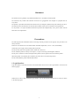
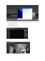
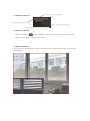
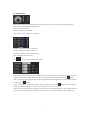
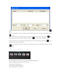
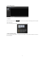
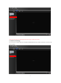
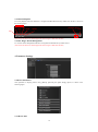
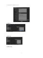
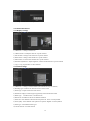
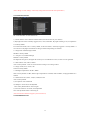
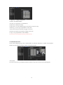
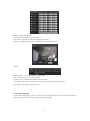
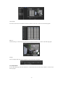
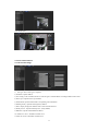
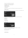
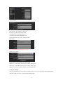
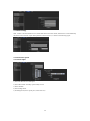
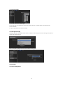
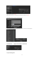
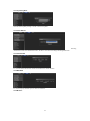
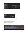
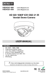
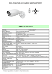
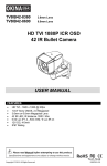
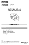
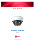
XL-ICA-370M2
Network camera
User manual
Contents
1. Login Interface .............................................................................................................................. 3
2. Preview ......................................................................................................................................... 4
2.1 Open/Close Preview ............................................................................................................ 5
2.2 Full-screen Preview............................................................................................................. 5
2.3 Electronic Zoom-in ............................................................................................................. 5
2.3 PTZ Control ........................................................................................................................ 6
3. File Management........................................................................................................................... 8
3.1 Search .................................................................................................................................. 8
3.2 Review Playback Image ...................................................................................................... 8
3.3 View Preview Image ........................................................................................................... 9
3.4 View Backup File .............................................................................................................. 10
3.4 View Images in File Management ..................................................................................... 10
4. Parameter Settings....................................................................................................................... 10
4.1 Device Parameters............................................................................................................. 10
4.1.1 Device Info ............................................................................................................. 10
4.1.2 RS232 ..................................................................................................................... 11
4.1.3 Decoder .................................................................................................................. 11
4.1.4 DST Setting ............................................................................................................ 11
4.2 Channel Parameters........................................................................................................... 12
4.2.1 Display Settings ..................................................................................................... 12
4.2.2 Video Settings ........................................................................................................ 12
4.2.3 Video Parameters ................................................................................................... 13
4.2.4 Schedule Record..................................................................................................... 13
4.2.5 Motion Detection ................................................................................................... 14
4.2.6 Video Tampering .................................................................................................... 15
4.2.7 Video Mask ............................................................................................................ 16
4.3 Network Parameters .......................................................................................................... 17
4.3.1 Network Settings .................................................................................................... 17
4.3.2 DDNS Settings ....................................................................................................... 18
4.3.3 NTP Settings .......................................................................................................... 18
4.3.4 Email Settings ........................................................................................................ 18
4.3.5 3G Settings .......................................................................................................... 19
4.3.6 WiFi Settings .......................................................................................................... 20
4.4 Alarm & Exception ........................................................................................................... 20
4.4.1 Alarm Input ............................................................................................................ 20
4.4.2 Alarm Output.......................................................................................................... 21
4.4.3 Exception Setting ................................................................................................... 21
4.5 User Info ........................................................................................................................... 21
4.5.1 User Management .................................................................................................. 21
1
4.5.2 Online User
display current online user information ...................................... 22
4.6 System Management ......................................................................................................... 22
4.6.1 System Update ....................................................................................................... 23
4.6.2 Auto Reboot ........................................................................................................... 23
4.6.3 Stream Info ............................................................................................................. 23
4.6.4 HD Disk ................................................................................................................. 23
4.6.5 Restore ................................................................................................................... 23
4.6.6 Local Setting .......................................................................................................... 24
5. Exit .............................................................................................................................................. 24
2
Statement
The instruction is for guidance only. Detailed information is in accordance with the product.
The instruction may include some technical inaccuracies or typographical error thought it is prepared with our
every effort.
The product or procedures described in the instruction may be changed or updated at any time without prior notice.
Screenshots used in the instruction are from the other machine and are only for indications and explanations.
For any doubts or to request documents about latest products and complementary notes, please consult with the
after-sales service department.
Precautions
The followings describe information about correct usage and risk prevention as well property loss prevention to be
strictly followed.
Please use web cameras in an environment within allowable temperature (-10°C to +55°C) and humidity.
Check if the power supply works normally before operation.
Do not furiously strike on the product and be careful not to fall it over.
Do not install the product in a dusty or moist place, or a place with strong electromagnetic radiation.
Do not place a container or others with liquid on the product or allow liquid to flow into inside the product.
When the product is left unused, place install the preventive dust cover for the image sensor.
Do not disassemble the product without authorization.
1. Login Interface
Type the IP address of the front-end device into the IE address bar to access to the Login interface, as shown in the
following figure:
Install Activex control. After entering the login interface, you will be asked to install the Activex control, as shown
in the following figure:
3
If it cannot be installed automatically, you can choose to manually install it. Then, you can:
Input user name: admin (default setting)
Input password: null (default setting)
Select language: Chinese or English
Click [Submit], as shown in the following figure:
2. Preview
4
2.1 Open/Close Preview
Click to open all the equipment
Click to open all the sub stream
Click to open a single device
Click to open a single device sub stream
2.2 Full-screen Preview
Click the full-screen icon
in the lower right corner to preview in full screen. In the preview window,
right click (or Esc key) to exit from full screen display.
2.3 Electronic Zoom-in
Use your mouse to select the preview channel to be zoomed in by scrolling the mouse wheel, as shown in the
following figure:
5
2.3 PTZ Control
PTZ control: you can use eight directional keys to rotate front-end devices, and AUTO indicates auto-rotation.
Zoom in/out: to adjust degree of zooming in/out
Focus: to adjust size of focus
Aperture: to adjust size of aperture
Speed: use the slider to regulate the PTZ speed
Bright: to adjust the brightness of the screen
Contrast: to adjust the contrast of the screen
Saturation: to adjust the saturation of the screen
Hue: to adjust the hue of the screen
The
arrow is used to restore default settings.
[Set a preset point] Set a preset point by using direction keys on the PTZ control to rotate the camera to the desired
location, and then select a preset number from the "preset point" drop-down list and then pressing
button.
[Call a preset point] Call a preset point by selecting a preset number to be called from the "preset point" drop-down
list and pressing
button.
[Set a cruise] Select a cruise number from the "cruise" drop-down list and press
button. The screen displays,
as shown in the following figure: (click cancel after setting to exit from this screen)
In the "cruise" setting page, select preset point, cruise time and cruise speed and then click "Add" button to add the
preset point for the cruise path (you can add several preset points). Click "Delete" button to delete a preset point.
6
[Call a cruise] Call a cruise by selecting a cruise number from the "cruise" drop-down list and then clicking "
"
button.
[Delete a cruise] Delete a cruise by selecting a cruise number from the "cruise" drop-down list and then clicking
"
" button.
[Set a locus] Select a locus number from the "Locus" drop-down list and click "enable locus memory"
Then perform PTZ controls, and click "disable locus memory"
button.
button. The locus is memorized.
[Call a locus] Call a locus by selecting a locus number from the "Locus" drop-down list and clicking
button.
(Currently, only one locus is supported)
[Delete a locus] Delete a locus by selecting a locus number from the "locus" drop-down list and then clicking
"
" button.
VOICE INTERCOM
Captur
Full Screen
Stop All
Voice
e
[Voice Intercom] click it to enable or disable voice intercom
[Capture] capture for preview. Click it to pop up its storage path automatically.
[Full screen] display the current preview in full screen
[Stop all] stop all current previews
[Voice] enable / disable front-end voice
Note: X indicates it is off or disabled
7
3. File Management
3.1 Search
Select the start time, and click the
button, the lower part displays searched images and videos (double
click to display files)
Note: You can change video or image storage path, which will be detailed later.
3.2 Review Playback Image
To review playback images under the C:\Program Files\PLAYBACK directory, double click the file, as shown in
the following figure:
8
(Note: the front end device should support SD card storage to enable this function)
3.3 View Preview Image
To review preview images under the C:\Program Files\PREVIEW directory, double click the file, as shown in the
following figure:
9
3.4 View Backup File
To review playback video files under the C:\Program Files\BACKUP directory, double click the file, as shown in
the following figure:
stop slow fast
frame
start
playback speed
voice
capture
(Note: the front end device should support SD card storage to enable this function)
3.4 View Images in File Management
To view files in file management under the C:\Program Files\FILE directory, double click it.
(Note: the front end device should support SD card storage to enable this function)
4. Parameter Settings
4.1 Device Parameters
Click parameter to display [Device info], [RS232], [Decoder] and [DST setting] options, as shown in the
following figure:
4.1.1 Device Info
10
To view and edit basic information of the device
4.1.2 RS232
To set RS232 parameters
4.1.3 Decoder
To set RS485 parameters (combined with PTZ)
4.1.4 DST Setting
11
DST setting: to enable and set DST parameter
4.2 Channel Parameters
4.2.1 Display Settings
1) Channel No.: to change a channel No.
2) Channel Name: to modify the name for a specific channel
3) Time Format: to change a time format for a specific channel
4) Date Format: to change a date format for a specific channel
5) OSD location: to set the name and time for a specific channel
6) Parameter adjustment: to adjust brightness, contrast and saturation for a specific channel
7) Copy: to copy set parameters to other channels
4.2.2 Video Settings
1) Channel No.: to change a channel number (the webcam has only one channel)
2) Encoding type: normal record, network record or event record
3) Stream type: complex stream and video stream
4) Resolution: displays resolution types supported by front-end Network camera
5) Bitrate type:
Constant bit rate or variable bit rate
6) Max bitrate: set different code rate for different channels
7) Frame rate: select different value from the drop-down list. FULL is used by default.
8) Video quality: select different video qualities as required. "Highest" is used by default.
9) Frame type: select different frame types
10) I frame interval: set I frame interval
12
(Note: change of "video settings" will directly change front-end Network camera parameters.)
4.2.3 Video Parameters
Set "Video Parameter" for front end devices
1) Current channel: select a different channel number (the webcam has only one channel)
2) Day/night auto switch: externally triggered, auto, color, black/white, day/night switching (0-30) is completed in
3 seconds by default.
For non-IR web models, auto is used by default; for IR web models, “externally triggered” is used by default. A
user can select a day/night switch mode according to models and operating environment.
3)Image mode: standard, bright, natural
Standard is used by default
4)Auto gain: low, medium and high
Medium is used by default
The higher the auto gain is, the higher the sensitivity in low illumination level is, but noise is more significant.
5)White balance: auto, indoor, outdoor
Auto is used by default. A user can switch modes according to its working scenario.
6)Image: normal, level, vertical, 180°
Normal is used by default
7)Backlight compensation: off, BLC, HBLC
OFF is used by default. For BLC, Black Light Compensation is enabled, while for HBLC, strong light inhibition is
enabled
8)Shutter mode: auto, flicker, 1/30(25)-1/5000, X2-X30
Auto is used by default
9) Lens aperture: auto and manual
10) Sharpness: on and off, 0-100 adjustable
On is used by default with its value being 80
11) 3D noise reduction: on and off, 0-100 adjustable
ON is used by default with its value being 25
(Note: this function should be support by front end devices)
4.2.4 Schedule Record
13
1) Channel No.: to change a channel No.
2) Enable: check Enable/Disable
3) All day: if it is checked, it is recorded all day
4) Week: select a different week day
5) Time section: you can set different types of records in 8 sections for a day
6) Week copy: you can copy set parameters to other weeks
7) Pre-record: set the pre-record time to trigger event record
8) Post-record: set the post-record time to trigger event record
9) Copy: to copy set parameters to other channels
(Note: the front end device should support SD card storage to enable this function)
4.2.5 Motion Detection
On the "Video Tampering" page, select a channel number for which the mask alarm is enabled. Check "Enable",
and then select the week to be armed, as shown in the following figure:
Arm schedule:
You can set 8 sections of arm schedule, and then copy them to each week, as shown in the following figure:
14
Settings on motion detection area:
Check "Drawing" to select the area to be detected
Click "Clear" to clear the designated area for the current channel
Sensitivity: the higher the sensitivity is, the better the motion detection effect is.
Linkage:
Alarm on monitor: view alarm information on the monitor
Audio warning: the device gives warning sound
Upload to center: view alarm information in the control center
Email linkage: after an alarm is triggered, it will send an email to the designated email address
Trigger alarm output: trigger related alarm device
4.2.6 Video Tampering
On the "Video Tampering" page, select a channel number for which the mask alarm is enabled. Check "Enable",
and then select the week to be armed, as shown in the following figure:
15
Arm schedule:
You can set 8 sections of arm schedule, and then copy them to each week, as shown in the following figure:
Mask set:
Check "Drawing" to set the area giving mask alarm, and adjust the sensitivity, as shown in the following figure:
Linkage:
Choose a linkage mode if an alarm is triggered, as shown in the following figure:
4.2.7 Video Mask
On the Video Mask page, select the channel No. to enable mask alarm, and then check "Enable", as shown in the
following figure:
16
Video Mask Effect
4.3 Network Parameters
4.3.1 Network Settings
1) NIC type: select a NIC type as required.
2) IP address: input IP address.
3) Auto config.: if this is enabled, the device will auto gain a valid IP address according to DHCP of the router.
4) Device port: input the device port number.
5) Subnet mask: input the subnet mask corresponding to this IP address.
6) Default gateway: input the related gateway address.
7) MAC: display the physical address of the current network interface.
8) HTTP port No.: input the related port No. (80 by default)
9) Multicast: input the related multicast address.
10) "DNS server adr 1": IP address of DNS server.
11) DNS server Adr 2: IP address of DNS server.
17
12) Alarm host IP: input the IP address of the alarm host.
13) "Alarm host port": input the port No. of the alarm host.
14) "Enable PPPOE" : check it to enable this feature.
·Input PPPOE user name.
·Input device dynamic address.
·Input PPPOE password.
·Confirm password.
15) Enable UPNP: if it is enabled, device port and HTTP port will automatically be mapped into the router.
4.3.2 DDNS Settings
DDNS is implemented through a dynamic domain resolution server. It requires a PC with fixed IP address on the
Internet, on which the dynamic domain resolution server runs.
1) Select DDNS server type (Ipserver, Dyndns, PeanutHull and 3322, currently, only 3322 is supported)
2) Input server name, for example, member.3322.org
3) Input port No.
4) Input user name.
5) Input password.
6) Confirm password.
7) Input spare domain.
4.3.3 NTP Settings
1) Input server address: IP address of NTP server.
2) NTP port: only TCP transmission is supported by SNTP. The port number is 123 by default.
3) Synchronize every: input the time interval to be adjusted.
4) Select time zone: optional time zone.
5) GMT: fine tune the time.
4.3.4 Email Settings
18
Outbox settings:
Email address: input the address of the outbox
Password: input the password of the outbox
Confirm password: confirm the password
Attachment: capture when attachment alarms
Identity verification: verify before sending an email
Inbox setting
(Note: you can set three receiving emails at most)
Sending server settings:
Sending interval: set the interval time to send an email
SMTP server: set the address of the smtp server for the sending email
POP3 server: set the address of the pop3 server for the sending email
SMTP port: set the port No. of the smtp server for the sending email
4.3.5 3G Settings
Connect to an external 3G device to enable 3G features. Select a device type, input phone number and then select
work state. Finally, click "Save", as shown in the following figure:
19
4.3.6 WiFi Settings
WiFi: connect to an external WiFi device, enable WiFi features and click refresh, and the device will automatically
search the wireless network. Input related parameters and click "Save", as shown in the following figure:
4.4 Alarm & Exception
4.4.1 Alarm Input
1) Select the alarm No. for alarm input
2) Select alarm status "Normally open/normally closed"
3) Alarm schedule
4) Select linkage mode
5) Set linkage PTZ (such as preset point, cruise and locus)
20
4.4.2 Alarm Output
1) Select the alarm No. for alarm output
2) Select the delay for outputting an alarm (when the alarm finishes, the alarm outputs in the delayed time)
3) Alarm schedule
4) Copy set parameters to the related week day
4.4.3 Exception Setting
Including: HDD full, HDD fault, network broken, IP address conflict, illegal access and video signal exception, as
shown in the following figure.
Their corresponding linkage modes are shown in the following figure:
4.5 User Info
4.5.1 User Management
21
Admin is the administrator (default)
Default indicates general users with permissions authorized to default users.(default)
Click [Add] to add a user, as shown in the following figure:
Click [RightsPermission] to assign permission to the new user, as shown in the following figure:
Click [Delete] to delete the new user
4.5.2 Online User
display current online user information
4.6 System Management
22
4.6.1 System Update
Click the related update package to locate it and click "Update".
4.6.2 Auto Reboot
Selecting
"maintenance mode" and "maintenance time", the device will reboot according to the designated mode.
4.6.3 Stream Info
To view information about main stream and sub stream of current channels.
4.6.4 HD Disk
To view its capacity and free space, as well as to format it.
4.6.5 Restore
23
Export: export all configurations to PC or USB
Import: import selected configuration to the system
Restore: restore default settings
Reboot: restart the system
4.6.6 Local Setting
Auto stream: if it is checked, sub stream is connected for small screen, and main stream is connected for large
screen.
Window mode: to set the aspect ratio of the preview window (filling, 4:3, 16:9)
Preview capture:
Playback capture:
Backup capture:
File capture:
to modify the path of the preview capture
to modify the path of the playback capture
to modify the path of the backup capture
to modify the path of the file capture
5. Exit
24