1
Operating Basics
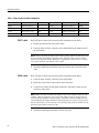
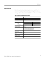
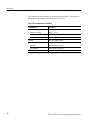
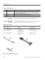
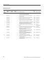
Table 1: Probe section and label combinations
Probe section
Channels
Label color
Probe section
Channels
Label color
A3-A2
CK:0, A3:7-0, A2:7-0
Tan
A1-A0
CK:1, A1:7-0, A0:7-0
Orange
D3-D2
QUAL:0, D3:7-0, D2:7-0
Blue
D1-D0
CK:2, D1:7-0, D0:7-0
Yellow
C3-C2
CK:3, C3:7-0, C2:7-0
White
C1-C0
QUAL:1, C1:7-0, C0:7-0
Gray
E3-E2
QUAL:3, E3:7-0, E2:7-0
Green
E1-E0
QUAL:2, E1:7-0, E0:7-0
Violet
P6417 Labels
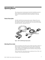
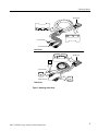
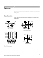
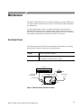
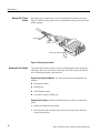
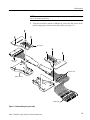
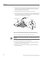
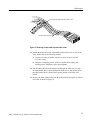
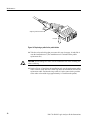
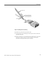
Refer to Figure 2 and use the following steps to attach the probe labels:
1. Identify the module end of the probe cable.
2. From the sheet of labels, locate the color-coded label for the module end of
the probe cable.
NOTE. When you install the labels on the P6417 probe, make sure that you select
the correct label for module end of the probe. The labels that connect to both
ends of the probe look similar, but differ in information content. Refer to Figure
2 to ensure you have selected the correct label.
3. Attach the matching colored label to the area on the other end of the probe
cable.
P6418 Labels
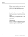
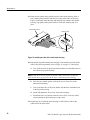
Refer to Figure 2 and use the following steps to attach the probe labels:
1. From the sheet of labels, locate the color-coded labels.
2. Install the correct label on the module end of the probe.
3. Locate the two labels for the podlet connectors, and attach a label on each
connector of the probe.
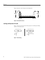
NOTE. Make sure that you attach the labels to the correct podlet connector. For
example, make sure that the A3 section at the podlet connector aligns with the
A3 section of the module end of the probe. The podlet connector adjacent to the
clock podlet has the higher-numbered channel group (if necessary, lay the probe
out on a flat surface so you can trace the channel groups from the module end of
the probe to the podlet connector end).
4. Attach the matching colored label to clock connector.
2
P4617 & P6418 Logic Analyzer Probe Instructions