1
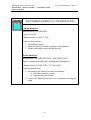
- PRO/010/M1 Rev 4 -
INGEGNERIA DEI SISTEMI S.p.A.
Rev. 1.1
N. doc.: MN/2009/056
RIS Hi-Mod / DUALF-400-900 Systems
Installation Guide and User Manual
RIS Hi-Mod /
DUALF-400-900 Installation Guide
and User Manual
Pisa, December 2010
Tot pag. N°. =
44
IDS Ingegneria Dei Sistemi S.p.A.
RIS Hi-Mod / DUALF-400-900 - Installation Guide
and User Manual
N. doc.: MN/2009/056 - Rev. 1.1
Document Evolution
Revision
Date
Reason for change
Rev. 1.0
August 2009
First edition
Rev. 1.1
December 2010
Document revision. Added DUALF-400-900 and
IC information
OUR CONTACTS
IDS Ingegneria dei Sistemi S.p.A. – GeoRadar Division
Via Enrica Calabresi, 24 – Loc. Montacchiello
56121 PISA - ITALY
Tel: +39.050.312411
Fax: +39.050.3124205
[email protected]
Customer Care department:
[email protected]
Tel.: +39.050.3124 355/356
Sales & Marketing department:
[email protected]
Tel.: +39.050.3124352
2 / 44
IDS Ingegneria Dei Sistemi S.p.A.
RIS Hi-Mod / DUALF-400-900 - Installation Guide
and User Manual
N. doc.: MN/2009/056 - Rev. 1.1
DISCLAIMER
IDS INCLUDING ITS SUBCONTRACTORS OR SUPPLIERS ARE NOT
RESPONSIBLE FOR ANY AND ALL CLAIMS RESULTING FROM THE
USE OF THE EQUIPMENT BY THE BUYER, WHETHER USED
SEPARATELY OR IN COMBINATION WITH OTHER PRODUCTS,
WHICH ASSUMES ALL RELEVANT RISKS AND LIABILITY.
EQUIPMENT
MAY
INCLUDE
SPECIFIC
“OPERATIONAL”
SOFTWARE WITH AUTOMATIC DATA PROCESSING AND
ANALYSIS TOOLS. WHILE EVERY EFFORT IS MADE TO ENSURE
THE ACCURACY OF THE INFORMATION PROVIDED BY THOSE
TOOLS, THEY MUST NOT BE INTENDED AS A SUBSTITUTE FOR
PEOPLE ANALYSIS; RATHER, THEY HAVE TO BE INTENDED AS
AN ADVISOR AND THE USER MUST BE AWARE THAT THE
RESULTS PROVIDED BY THEM MAY BE NOT ABSOLUTELY
ERROR FREE AND MUST NOT COMPLETELY RELY ON THE
RESULTS PROVIDED BY THEM. IDS ASSUMES NO LIABILITY FOR
ANY
DIRECT,
INDIRECT
SPECIAL,
INCIDENTAL
OR
CONSEQUENTIAL DAMAGES OR INJURIES CAUSED BY SUCH
RELIANCE. ANY PERSON OR ENTITY, WHO COMPLETELY RELIES
ON INFORMATION OBTAINED FROM THE AUTOMATED DATA
PROCESSING/ANALYSIS TOOLS ONLY, DOES SO AT HIS/HER OWN
RISK.
3 / 44
IDS Ingegneria Dei Sistemi S.p.A.
RIS Hi-Mod / DUALF-400-900 - Installation Guide
and User Manual
N. doc.: MN/2009/056 - Rev. 1.1
SAFETY INFORMATION
The equipment conforms to the following requirements set by EC
regulations, including subsequent modifications, and to the legislation set
by the member states that implement these regulations:
1999/05/EEC Radio Directive
Warning: this equipment is destined for use in industrial environments
(Class A apparatus). In residential, commercial and light industry
environments, this apparatus may generate radio interference: in this case,
the user may be required to operate while taking appropriate
countermeasures.
The apparatus is sensitive to the presence of external electromagnetic fields,
which may reduce its performance.
4 / 44
IDS Ingegneria Dei Sistemi S.p.A.
RIS Hi-Mod / DUALF-400-900 - Installation Guide
and User Manual
N. doc.: MN/2009/056 - Rev. 1.1
IMPORTANT NOTE FOR THE US CUSTOMERS
FCC ID: UFW-HI-MOD
This device complies with part 15 of the FCC Rules:
Operation is subject to the following conditions:
1. This device may not cause harmful interference, and
2. This device must accept any interference received, Including interference that may cause undesired
operation
Warning: Changes or modifications to this unit not expressly approved by the party responsible for
compliance could void the user’s authority to operate the equipment.
Operation of this device is restricted to law enforcement, fire and rescue officials, scientific research
institutes, commercial mining companies, and construction companies. Operation by any other party is a
violation of 47 U.S.C. § 301 and could subject the operator to serious legal penalties.
Coordination Requirements.
(a) UWB imaging systems require coordination through the FCC before the equipment may be used. The
operator shall comply with any constraints on equipment usage resulting from this coordination.
(b) The users of UWB imaging devices shall supply detailed operational areas to the FCC Office of
Engineering and Technology who shall coordinate this information with the Federal Government through
the National Telecommunications and Information Administration. The information provided by the UWB
operator shall include the name, address and other pertinent contact information of the user, the desired
geographical area of operation, and the FCC ID number and other nomenclature of the UWB device. This
material shall be submitted to the following address:
Frequency Coordination Branch., OET
Federal Communications Commission
445 12th Street, SW
Washington, D.C. 20554
ATTN: UWB Coordination
(d) Users of authorized, coordinated UWB systems may transfer them to other qualified users and to
different locations upon coordination of change of ownership or location to the FCC and coordination with
existing authorized operations.
(e) The NTIA/FCC coordination report shall include any needed constraints that apply to day-to-day
operations. Such constraints could specify prohibited areas of operations or areas located near authorized
radio stations for which additional coordination is required before operation of the UWB equipment. If
additional local coordination is required, a local coordination contact will be provided.
(f) The coordination of routine UWB operations shall not take longer than 15 business days from the receipt
of the coordination request by NTIA. Special temporary operations may be handled with an expedited turnaround time when circumstances warrant. The operation of UWB systems in emergency situations
involving the safety of life or property may occur without coordination provided a notification procedure,
similar to that contained in CFR47 Section 2.405(a)-(e), is followed by the UWB equipment user.
Notice: Use of this device as a wall imaging system is prohibited by FCC regulations.
5 / 44
IDS Ingegneria Dei Sistemi S.p.A.
RIS Hi-Mod / DUALF-400-900 - Installation Guide
and User Manual
N. doc.: MN/2009/056 - Rev. 1.1
IMPORTANT NOTE FOR THE US CUSTOMERS
FCC ID: UFW-DUALF-400-900
This device complies with part 15 of the FCC Rules:
Operation is subject to the following conditions:
1. This device may not cause harmful interference, and
2. This device must accept any interference received, Including interference that may cause undesired
operation
Warning: Changes or modifications to this unit not expressly approved by the party responsible for
compliance could void the user’s authority to operate the equipment.
Operation of this device is restricted to law enforcement, fire and rescue officials, scientific research
institutes, commercial mining companies, and construction companies. Operation by any other party is a
violation of 47 U.S.C. § 301 and could subject the operator to serious legal penalties.
Coordination Requirements.
(a) UWB imaging systems require coordination through the FCC before the equipment may be used. The
operator shall comply with any constraints on equipment usage resulting from this coordination.
(b) The users of UWB imaging devices shall supply detailed operational areas to the FCC Office of
Engineering and Technology who shall coordinate this information with the Federal Government through
the National Telecommunications and Information Administration. The information provided by the UWB
operator shall include the name, address and other pertinent contact information of the user, the desired
geographical area of operation, and the FCC ID number and other nomenclature of the UWB device. This
material shall be submitted to the following address:
Frequency Coordination Branch., OET
Federal Communications Commission
445 12th Street, SW
Washington, D.C. 20554
ATTN: UWB Coordination
(d) Users of authorized, coordinated UWB systems may transfer them to other qualified users and to
different locations upon coordination of change of ownership or location to the FCC and coordination with
existing authorized operations.
(e) The NTIA/FCC coordination report shall include any needed constraints that apply to day-to-day
operations. Such constraints could specify prohibited areas of operations or areas located near authorized
radio stations for which additional coordination is required before operation of the UWB equipment. If
additional local coordination is required, a local coordination contact will be provided.
(f) The coordination of routine UWB operations shall not take longer than 15 business days from the receipt
of the coordination request by NTIA. Special temporary operations may be handled with an expedited turnaround time when circumstances warrant. The operation of UWB systems in emergency situations
involving the safety of life or property may occur without coordination provided a notification procedure,
similar to that contained in CFR47 Section 2.405(a)-(e), is followed by the UWB equipment user.
Notice: Use of this device as a wall imaging system is prohibited by FCC regulations.
6 / 44
IDS Ingegneria Dei Sistemi S.p.A.
RIS Hi-Mod / DUALF-400-900 - Installation Guide
and User Manual
N. doc.: MN/2009/056 - Rev. 1.1
IMPORTANT NOTE FOR THE CANADIAN CUSTOMERS
IC Certification Number: IC:8991A –HIMOD
This device complies with the requirements of IC Standard RSS-220
This Ground Penetrating Radar Device shall be operated only when in contact with or within 1 m of the ground.
This Ground Penetrating Radar Device shall be operated only by law enforcement agencies, scientific research
institutes, commercial mining companies, construction companies, and emergency rescue or firefighting
organizations.
IMPORTANT NOTE FOR THE CANADIAN CUSTOMERS
IC Certification Number: IC:8991A –DUALF400900
This device complies with the requirements of IC Standard RSS-220
This Ground Penetrating Radar Device shall be operated only when in contact with or within 1 m of the ground.
This Ground Penetrating Radar Device shall be operated only by law enforcement agencies, scientific research
institutes, commercial mining companies, construction companies, and emergency rescue or firefighting
organizations.
!
CLEANING INFORMATION
WARNING
Before cleaning any external parts of the apparatus, make sure
that all cables have been disconnected, including the power
supply cable. If a damp cloth is used, make sure it is not too wet,
to avoid any damage to the electrical components of the
equipment. Wait until the equipment is totally dry before
reconnecting the cables.
The Detector Duo should be cleaned periodically using a damp
cloth.
Do not use solvents or abrasive detergents.
Do not apply liquid directly to the electrical contacts of the
various connectors. If a specific spray is used to clean the PC
TFT monitor, make sure it is not flammable; ion any case, do not
spray it directly on the screen, instead, spray it onto the cleaning
cloth.
7 / 44
IDS Ingegneria Dei Sistemi S.p.A.
RIS Hi-Mod / DUALF-400-900 - Installation Guide
and User Manual
N. doc.: MN/2009/056 - Rev. 1.1
BATTERIES REMOVAL INFORMATION
Laptop Batteries:
Manufacturer: PANASONIC
Type: Li-ion Ni
Characteristics: 10.65V 5.7Ah
Removal instructions:
1. turn off the laptop;
2. open the drawer with the symbol of the batteries;
3. extract the battery pack pulling the tab.
Radar batteries:
Manufacturer: FIAMM FG21202 / SAFT MP176065
Type: rechargeable lead acid / rechargeable lithium-ion
Characteristics: 12V & 12Ah / 15V & 6.8Ah
Removal instructions:
1. disconnect the battery from the instrument:
a. pull the connector wings;
b. separate the connectors;
2. remove the battery from the cover (optional) opening the
strap.
8 / 44
IDS Ingegneria Dei Sistemi S.p.A.
RIS Hi-Mod / DUALF-400-900 - Installation Guide
and User Manual
N. doc.: MN/2009/056 - Rev. 1.1
RECICLYING
The crossed out wheeled bin symbol shown on the equipment indicates that
the product must be recycled separately from other waste at the end of its
useful life.
Separate waste disposal of this product at the end of its useful life will be
organised and managed by IDS. When you decide to dispose of the
equipment, contact IDS and follow the system that IDS has set up to permit
the separate collection of the apparatus at its life end.
Adequate separate collection for its subsequent recycling, treatment and
environmental friendly disposal contribute towards avoiding any
unnecessary effects on the environment and to health and favour the reuse or
recycling of the materials that make up the equipment. Unauthorised disposal
of this product as unsorted waste by its possessor will lead to an
administrative penalty foreseen by national regulations.
9 / 44
IDS Ingegneria Dei Sistemi S.p.A.
RIS Hi-Mod / DUALF-400-900 - Installation Guide
and User Manual
N. doc.: MN/2009/056 - Rev. 1.1
WARRANTY CERTIFICATE CONDITIONS
A.
1.
Standard Warranty Conditions
IDS Ingegneria dei Sistemi S.p.A, (hereinafter referred to as IDS or Seller), warrants that its
products shall be free from defects in material and workmanship, for a period of 12 months
from the delivery date duly registered and certified (“Effective Date”) in the “Warranty
Registration Form”. IDS shall repair or replace Products or parts thereof found faulty (the
“Faulty Parts”) which are returned to IDS, and which, at IDS’s judgment, were defective or
became defective during its normal use. Seller’s obligations shall not apply to Faulty Parts
that:
(a) Buyer do not properly store, install, use, or maintain;
(b) Buyer modify, or perform tests which are not approved in writing by the Seller;
(c) Buyer have subjected to any kind of misuse, detrimental exposure beyond its
intended purpose or damaged in an accident or by natural disaster or calamities.
(d) Are repaired by other than IDS personnel; in which have been installed HW/SW
accessories not supplied by IDS; are integrated or connected to equipment
different from the ones supplied by IDS (except the PC data Logger conform to
IDS specifications);
(e) Whose operational software was not installed as per IDS instruction (see IDS
User’s Guide for the Data Acquisition Software);
B.
Warranty Procedure
1.
To proceed in the application of warranty terms, Buyer shall have to contact IDS Customer
Care Office to get the clearance to return the Faulty Parts.
2.
The Faulty Parts once received by IDS will be inspected to verify they are eligible for repair
or replacement..
3.
Buyer is responsible for ensuring that the Faulty Parts be returned to IDS with a suitable
packing (it is recommended that the original packing be saved for a better understand of the
failure cause); IDS will not be obliged to repair or replace Faulty Parts damaged from abuse,
misuse, negligence, accident loss or damage in transit.
4.
The Shipping costs for Products returned during the warranty period, are as follows:
(f)
5.
C.
1.
D.
2.
From Buyer Site to Seller site
by Buyer
shipping costs, as per Incoterms CIP, are borne
(g) From Seller Site to Buyer site
Seller
shipping cost, as per Incoterms CIP, are borne by
The warranty period on the repaired or replaced Faulty Parts is six months or the unexpired
portion of warranty on such Faulty Parts whichever date comes later.
Special Warranty Terms for IBIS – M Units
IDS offers the Buyer special Support and Maintenance Plans to be executed conditionally by
the Buyer. These Plans set forth special Warranty conditions which are detailed in the
relevant options purchased.
Limited Liability
Seller’s sole obligation and liability under this Agreement shall be limited to the repair or
replacement of the Product, or the refund of the purchase price at the Seller’s sole option.
This Article sets forth the sole and exclusive remedies for claims based upon defects or
nonconformity of the Products, whether the claim is on contract, warranty, tort (including
negligence), strict liability, or otherwise.
10 / 44
IDS Ingegneria Dei Sistemi S.p.A.
RIS Hi-Mod / DUALF-400-900 - Installation Guide
and User Manual
N. doc.: MN/2009/056 - Rev. 1.1
3.EXCEPT AS PROVIDED IN THIS DOCUMENT, THE FOREGOING WARRANTIES ARE
IN LIEU OF ALL OTHER WARRANTIES, AND SELLER MAKES NO OTHER
WARRANTIES WHETHER WRITTEN, ORAL, EXPRESS, IMPLIED, OR STATUTORY,
INCLUDING BUT NOT LIMITED TO, WARRANTIES OF MERCHANTABILITY OR
FITNESS FOR PARTICULAR PURPOSE.
11 / 44
IDS Ingegneria Dei Sistemi S.p.A.
RIS Hi-Mod / DUALF-400-900 - Installation Guide
and User Manual
N. doc.: MN/2009/056 - Rev. 1.1
INDEX
1. Hardware equipment of the Hi-MOD AND DUALF-400-900 systems ................ 15
Rudder ....................................................................................................................... 15
1.1.1 Assemblage instructions ................................................................................... 16
1.1.2 Wiring............................................................................................................... 20
1.2 Two antennas equipment and configuration ...................................................... 22
Rudder ....................................................................................................................... 23
1.2.1 Assemblage instructions ................................................................................... 23
1.2.2 Wiring............................................................................................................... 26
1.3 Three antennas equipment and configuration .................................................... 27
1.3.1 Assemblage instructions ................................................................................... 28
1.3.2 Wiring............................................................................................................... 30
1.4 Four antennas equipment and configuration ..................................................... 31
1.4.1 Assemblage instructions ................................................................................... 32
1.4.2 Wiring............................................................................................................... 32
2. The DAD Control Unit .............................................................................................. 34
2.1 The Notebook Computer ..................................................................................... 36
2.1.1 Panasonic Toughbook rugged tablet PC .......................................................... 36
2.2 Connecting the DAD Control Unit - Notebook Computer ................................. 38
2.3 Wireless connection ............................................................................................ 40
3. On line assistance....................................................................................................... 42
3.1 Remote assistance using Webex Support Center ................................................ 42
3.1.1 How to use the Webex service ......................................................................... 42
FIGURES INDEX
FIG. 1.1 – EQUIPMENT PROVIDED FOR MONO ANTENNA CONFIGURATION . 15
FIG. 1.2 – RUDDER IN MONO ANTENNA CONFIGURATION ................................ 16
FIG. 1.3 – RUDDER KNOBS: BIGGER ONE ON THE LEFT, SMALLER ONE ON
THE RIGHT .............................................................................................................. 17
FIG. 1.4 – ANTENNA FRAME EQUIPMENT ............................................................... 17
FIG. 1.5 – CONNECTION PIPES IN POSITION AND CLOSED FRAME ................... 18
FIG. 1.6 – INSERTION OF THE RUDDER .................................................................... 18
FIG. 1.7 – CLOSE UP OF THE METALLIC FRAMES (UP) AND LOCKING DEVICE
(DOWN) .................................................................................................................... 19
FIG. 1.8 – INSERTION OF THE ANTENNA AND CLOSE UP OF THE HOOK ........ 19
FIG. 1.9 – INSERTION OF THE DAD CONTROL UNIT AND BATTERY ................ 20
12 / 44
IDS Ingegneria Dei Sistemi S.p.A.
RIS Hi-Mod / DUALF-400-900 - Installation Guide
and User Manual
N. doc.: MN/2009/056 - Rev. 1.1
FIG. 1.10 – MAGNETIC ENCODER CABLE ................................................................ 20
FIG. 1.11 – ANTENNA CABLE IN PLACE ................................................................... 21
FIG. 1.12 – BATTERY CABLE AND LAN CABLE ...................................................... 21
FIG. 1.13 – EQUIPMENT PROVIDED FOR THE TWO ANTENNAS
CONFIGURATION .................................................................................................. 23
FIG. 1.14 – TWO ANTENNAS RUDDER CONFIGURATION..................................... 23
FIG. 1.15 – TWO ANTENNAS FRAME EQUIPMENT ................................................. 24
FIG. 1.16 – MAKING THE TWO ANTENNAS FRAME ............................................... 25
FIG. 1.17 – INSERTION AND LOCKING OF THE RUDDER ..................................... 25
FIG. 1.18 – INSERTION OF THE ANTENNAS AND CLOSE-UP OF THE HOOK .... 26
FIG. 1.19 – DAD UNIT POSITIONING AND BATTERY BAGS ................................. 26
FIG. 1.20 – ANTENNA CABLES .................................................................................... 27
FIG. 1.21 - EQUIPMENT PROVIDED FOR THE THREE ANTENNAS
CONFIGURATION .................................................................................................. 28
FIG. 1.22 – SIDE ANTENNA FRAMES PARTS ............................................................ 28
FIG. 1.23 – SIDE ANTENNA FRAME............................................................................ 29
FIG. 1.24 – MAIN FRAME “MUSHROOMS” & LOCKING DEVICE ......................... 29
FIG. 1.25 - INSERTION OF ONE ANTENNA AND CLOSE-UP OF THE HOOK ...... 30
FIG. 1.26 – ANTENNA CABLES .................................................................................... 30
FIG. 1.27 – THREE ANTENNAS CONFIGURATION .................................................. 31
FIG. 1.28 - EQUIPMENT PROVIDED FOR THE FOUR ANTENNAS
CONFIGURATION .................................................................................................. 32
FIG. 1.29 – ANTENNA CABLES .................................................................................... 33
FIG. 1.30 – FOUR ANTENNAS CONFIGURATION .................................................... 33
FIG. 2.1 – DAD SIDE FAST WAVE WITH BATTERY PORT, LAN PORT AND
WIRELESS CONNECTOR ...................................................................................... 34
FIG. 2.2 – –DAD SIDE FAST WAVE WITH CONNECTIONS TO POSITION SENSOR
AND ANTENNAE.................................................................................................... 35
FIG. 2.3 – EXAMPLE OF ANTENNA WITH A 19 POLE CONNECTOR AND
POSSIBILITY OF A CASCADE CONNECTION .................................................. 35
FIG. 2.4 – 19-11 POLE ADAPTOR ................................................................................. 36
FIG. 2.5 – PANASONIC TOUGHBOOK CF-19 ............................................................. 37
FIG. 2.6 – LAN CABLE ................................................................................................... 38
FIG. 2.7 – LAN CABLE CONNECTION BETWEEN THE NOTEBOOK COMPUTER
AND THE DAD CONTROL UNIT ......................................................................... 38
FIG. 2.8 – BATTERY CABLE ......................................................................................... 39
FIG. 2.9 – CONNECTING THE DAD CONTROL UNIT TO THE BATTERY PACK
AND SWITCHING ON BUTTON (RED COLOR) ................................................. 39
FIG. 2.10 – WIRELESS PORT TO BE ACTIVATED ON CF-19 .................................. 40
FIG. 2.11 – WIRELESS CONNECTION ON THE DAD ................................................ 41
FIG. 2.12 – CONFIGURATION FILE FOR WIRELESS CONNECTION ..................... 41
13 / 44
IDS Ingegneria Dei Sistemi S.p.A.
RIS Hi-Mod / DUALF-400-900 - Installation Guide
and User Manual
N. doc.: MN/2009/056 - Rev. 1.1
FIG. 3.1 – MAIL SENT BY IDS TO THE CLIENT ........................................................ 42
FIG. 3.2 – CLIENT DATA INSERTION FORM ............................................................. 43
FIG. 3.3 – WEBEX SET UP WINDOW ........................................................................... 43
FIG. 3.4 – WELCOME TO WEBEX SUPPORT CENTER WINDOW .......................... 44
FIG. 3.5 – COMMAND ACCEPTANCE WINDOW ...................................................... 44
14 / 44
IDS Ingegneria Dei Sistemi S.p.A.
RIS Hi-Mod / DUALF-400-900 - Installation Guide
and User Manual
N. doc.: MN/2009/056 - Rev. 1.1
1. HARDWARE EQUIPMENT OF THE HI-MOD AND DUALF-400-900
SYSTEMS
Hi-MOD and DUALF-400-900 systems offers you the possibility to choose up to
four different equipments, matching the number of antennas you want to use. This
handbook shows you the equipment you will receive and guides you through the
configuration of your hardware.
One antenna equipment and configuration (Fig. 1.1) shows you the equipment you
will receive for your mono antenna configuration. The equipment is composed of:
•
A Rudder
•
Two Wheel frames
•
Two Connection pipes
•
An Antenna and its cable
•
A Battery and its cable
•
DAD control unit
•
LAN cable
Wheel
frames
Antenna
Rudder
Connection
Pipes
Antenna
Cable
Battery and
DAD
LAN Cable
Fig. 1.1 – Equipment provided for mono antenna configuration
15 / 44
Battery
Cable
IDS Ingegneria Dei Sistemi S.p.A.
RIS Hi-Mod / DUALF-400-900 - Installation Guide
and User Manual
N. doc.: MN/2009/056 - Rev. 1.1
1.1.1 Assemblage instructions
First you have to set the rudder in its mono antenna setting. The rudder has two
free bars and four knobs (Fig. 1.2). The bigger ones must be screwed in vertically
to block the free bars in place while the little ones can be screwed in two different
position: if placed on the inside part of the frame you will get the mono or three
antenna configuration (Fig. 1.3); if placed on the external part of the frame you
will get the two or four antenna configuration (Fig. 1.14).
Fig. 1.2 – Rudder in mono antenna configuration
16 / 44
IDS Ingegneria Dei Sistemi S.p.A.
RIS Hi-Mod / DUALF-400-900 - Installation Guide
and User Manual
N. doc.: MN/2009/056 - Rev. 1.1
Fig. 1.3 – Rudder knobs: bigger one on the left, smaller one on the right
Now you have to build the frame carrying the antenna: you will need the
equipment shown in Fig. 1.4. Take one of the wheel frame and screw the two
connection pipes in it, then close the frame with the other wheel part (Fig. 1.5).
Fig. 1.4 – Antenna frame equipment
17 / 44
IDS Ingegneria Dei Sistemi S.p.A.
RIS Hi-Mod / DUALF-400-900 - Installation Guide
and User Manual
N. doc.: MN/2009/056 - Rev. 1.1
Fig. 1.5 – Connection pipes in position and closed frame
Place the rudder into the metallic connections of the wheel frame as shown in Fig.
1.6 then insert the two locking devices shown in Fig. 1.7 in the metallic
connections. The locking devices are the two knobs with a little button in their
centres: you have to push it , insert the knob in place and then release it.
Fig. 1.6 – Insertion of the rudder
18 / 44
IDS Ingegneria Dei Sistemi S.p.A.
RIS Hi-Mod / DUALF-400-900 - Installation Guide
and User Manual
N. doc.: MN/2009/056 - Rev. 1.1
Fig. 1.7 – Close up of the metallic frames (up) and locking device (down)
Take the antenna and make it slide in the frame from behind. Remember to put
and remove the antenna always from the rear part of the frame. When the antenna
is in place lock it around the two connection pipes using its four hooks (Fig. 1.8).
Fig. 1.8 – Insertion of the antenna and close up of the hook
19 / 44
IDS Ingegneria Dei Sistemi S.p.A.
RIS Hi-Mod / DUALF-400-900 - Installation Guide
and User Manual
N. doc.: MN/2009/056 - Rev. 1.1
Finally put the DAD Control unit inside the box in the middle of the rudder (Fig.
1.9) and the battery in one of the two small black bags.
Fig. 1.9 – Insertion of the DAD Control Unit and battery
1.1.2 Wiring
Once the DAD unit is in place you have to connect it with the magnetic encoder,
the antenna, the battery and your laptop.
The magnetic encoder cable is located on one of the wheel frames. Let it pass
through the black strip on the rudder until you reach the first ferrite then link the
connector with the Wheel port of the DAD unit (Fig. 1.10).
Fig. 1.10 – Magnetic encoder cable
20 / 44
IDS Ingegneria Dei Sistemi S.p.A.
RIS Hi-Mod / DUALF-400-900 - Installation Guide
and User Manual
N. doc.: MN/2009/056 - Rev. 1.1
Take the Antenna cable and link the IN port of the antenna box with the
ANT1/CHAIN port of the DAD unit (Fig. 1.11).
Fig. 1.11 – Antenna cable in place
Battery cable has two connectors of different shapes in order to help you: one of
them must be linked with the battery, the other one with the DAD unit (Fig. 1.12).
Fig. 1.12 – Battery cable and LAN cable
Fig. 1.12 shows also the LAN cable connector. You have to link the other end of
this cable with the LAN port of your laptop.
21 / 44
IDS Ingegneria Dei Sistemi S.p.A.
RIS Hi-Mod / DUALF-400-900 - Installation Guide
and User Manual
N. doc.: MN/2009/056 - Rev. 1.1
You can find more info about the DAD unit and its cable connectors in Chapter 2:
The DAD control unit.
1.2 Two antennas equipment and configuration
Fig. 1.13 shows you the equipment you will receive for your two antennas
configuration. The equipment is composed of:
•
A Rudder
•
Two Wheeled frames
•
One non-Wheeled frame
•
Four Connection pipes
•
Two Antennas and their cables (one short, one long)
•
Two Batteries and their cable
•
DAD control unit
•
LAN cable
22 / 44
IDS Ingegneria Dei Sistemi S.p.A.
RIS Hi-Mod / DUALF-400-900 - Installation Guide
and User Manual
N. doc.: MN/2009/056 - Rev. 1.1
Wheeled
frames
Rudder
Antennas
Connection
Pipes
Battery &
LAN cables
Antenna
cables
Nonwheeled
frame
DAD unit &
Batteries
Fig. 1.13 – Equipment provided for the two antennas configuration
1.2.1 Assemblage instructions
First you have to set the rudder in its two antennas setting. The rudder has two free
bars and four knobs (Fig. 1.2). The bigger ones must be screwed in vertically to
block the free bars in place while the little ones can be screwed in two different
position: if placed on the inside part of the frame you will get the mono or three
antenna configuration (Fig. 1.3); if placed on the external part of the frame you
will get the two or four antenna configuration (Fig. 1.14).
Fig. 1.14 – Two antennas rudder configuration
23 / 44
IDS Ingegneria Dei Sistemi S.p.A.
RIS Hi-Mod / DUALF-400-900 - Installation Guide
and User Manual
N. doc.: MN/2009/056 - Rev. 1.1
To build the frame carrying the antennas you need the equipment shown in Fig.
1.15.
Fig. 1.15 – Two Antennas frame equipment
Take one of the wheeled frames and screw two connection pipes in it. Connect
these pipes with the non-wheeled frame (the white spots on it show you which
side goes down). Link the other two connection pipes and finally close the box
with the other wheeled frame.
Fig. 1.16 shows you how to build the box.
Now take the rudder and put it in the metallic connections of the wheeled frames.
Be sure to lock it with the knobs showed in Fig. 1.17.
The locking devices are the two knobs with a little button in their centres: you
have to push it , insert the knob in place and then release it.
24 / 44
IDS Ingegneria Dei Sistemi S.p.A.
RIS Hi-Mod / DUALF-400-900 - Installation Guide
and User Manual
N. doc.: MN/2009/056 - Rev. 1.1
Fig. 1.16 – Making the two antennas frame
Fig. 1.17 – Insertion and locking of the rudder
Take the antennas and make them slide in the frame from behind. Remember to
put and remove the antennas always from the rear part of the frame. When the
antennas are in place lock them around the four connection pipes using their hooks
(Fig. 1.18).
25 / 44
IDS Ingegneria Dei Sistemi S.p.A.
RIS Hi-Mod / DUALF-400-900 - Installation Guide
and User Manual
N. doc.: MN/2009/056 - Rev. 1.1
Fig. 1.18 – Insertion of the antennas and close-up of the hook
Place the DAD control unit inside the box on the rudder and the batteries in the
two little black bags (Fig. 1.19).
Fig. 1.19 – DAD unit positioning and Battery bags
1.2.2 Wiring
Battery, wheel and LAN cables are linked to the DAD control unit as in the mono
antenna configuration (see Par 1.1.2 Wiring for further instruction).
In the two antennas configuration you have two antenna cables. The longer one
must connect the ANT1/CHAIN port of the DAD unit with the IN port of the first
antenna on the left; the shorter cable makes a cascade connection linking the OUT
port of the first antenna with the IN port of the second one (Fig. 1.20).
26 / 44
IDS Ingegneria Dei Sistemi S.p.A.
RIS Hi-Mod / DUALF-400-900 - Installation Guide
and User Manual
N. doc.: MN/2009/056 - Rev. 1.1
Fig. 1.20 – Antenna cables
You can find more info about the DAD unit and its cable connectors in Chapter 2:
The DAD control unit.
1.3 Three antennas equipment and configuration
Fig. 1.21 shows you the equipment you will receive for your three antennas
configuration. The equipment is composed of:
•
A Rudder
•
Four Wheeled frames (two of them with battery bags)
•
Two non-Wheeled frames
•
Six Connection pipes
•
Three Antennas and their cables (two short, one long)
•
Two Batteries and their cable
•
DAD control unit
•
LAN cable
27 / 44
IDS Ingegneria Dei Sistemi S.p.A.
RIS Hi-Mod / DUALF-400-900 - Installation Guide
and User Manual
N. doc.: MN/2009/056 - Rev. 1.1
Wheeled
frames
Rudder
Antennas
Antenna
cables
Battery &
LAN cables
Batteries &
DAD
Connection
pipes
Non-wheeled
frames
Fig. 1.21 - Equipment provided for the three antennas configuration
1.3.1 Assemblage instructions
First you must set the system in its mono antenna configuration (see Par 1.1.1),
then you have to build the frames for the antennas on the side. Equipment needed
for the side frames is shown in Fig. 1.22.
Fig. 1.22 – Side antenna frames parts
28 / 44
IDS Ingegneria Dei Sistemi S.p.A.
RIS Hi-Mod / DUALF-400-900 - Installation Guide
and User Manual
N. doc.: MN/2009/056 - Rev. 1.1
Take one of the wheeled frames and screw two connection pipes in it. After that
close the box using one of the non-wheeled frames as shown in Fig. 1.23.
Fig. 1.23 – Side antenna frame
Unite the side frame with the central one by linking the metallic locks with the
wheels “mushrooms”. Lock up the structure by turning the switches (Fig. 1.24).
Do the same operations to build and place the box on the other side.
“Mushroom”
Locking
device
Fig. 1.24 – Main frame “mushrooms” & locking device
Take the antennas and make them slide in the side frames from behind. Remember
to put and remove the antennas always from the rear part of the frames. When the
antennas are in place lock them around the connection pipes using their hooks
(Fig. 1.25).
29 / 44
IDS Ingegneria Dei Sistemi S.p.A.
RIS Hi-Mod / DUALF-400-900 - Installation Guide
and User Manual
N. doc.: MN/2009/056 - Rev. 1.1
Fig. 1.25 - Insertion of one antenna and close-up of the hook
1.3.2 Wiring
Battery, wheel and LAN cables are linked to the DAD control unit as in the mono
antenna configuration (see Par 1.1.2 Wiring for further instruction).
In the three antennas configuration you have three antenna cables. To make a
cascade connection between the antennas you have to link the longer cable from
the ANT1/CHAIN port of the DAD unit to the IN port of the leftmost antenna; use
the two short cable to link OUT and IN ports of each adjacent antenna (Fig. 1.26).
The complete three antenna configuration in shown in Fig. 1.27.
Fig. 1.26 – Antenna cables
30 / 44
IDS Ingegneria Dei Sistemi S.p.A.
RIS Hi-Mod / DUALF-400-900 - Installation Guide
and User Manual
N. doc.: MN/2009/056 - Rev. 1.1
Fig. 1.27 – Three antennas configuration
You can find more info about the DAD unit and its cable connectors in Chapter 2:
The DAD control unit.
1.4 Four antennas equipment and configuration
Fig. 1.28 shows you the equipment you will receive for your four antennas
configuration. The equipment is composed of:
•
A Rudder
•
Four Wheeled frames (two of them with battery bags)
•
Three non-Wheeled frames (two of them with metallic lock devices)
•
Eight Connection pipes
•
Four Antennas and their cables (three short, one long)
•
Two Batteries and their cable
•
DAD control unit
•
LAN cable.
31 / 44
IDS Ingegneria Dei Sistemi S.p.A.
RIS Hi-Mod / DUALF-400-900 - Installation Guide
and User Manual
N. doc.: MN/2009/056 - Rev. 1.1
Antennas
Rudder
Battery and
LAN cables
Antenna
cables
Connection
pipes
Batteries &
DAD control
unit
Wheeled
frames
Non-wheeled
frames
Fig. 1.28 - Equipment provided for the four antennas configuration
1.4.1 Assemblage instructions
First of all follow the instruction to set the system in the two antennas
configuration (see Par 1.2.1). Then build and place the two side frames as
described in Par. 1.3.1. Finally insert the third and forth antenna in the side frames.
1.4.2 Wiring
Battery, wheel and LAN cables are linked to the DAD control unit as in the mono
antenna configuration (see Par 1.1.2 for further instruction).
In the four antennas configuration you have four antenna cables. To make a
cascade connection between the antennas you have to link the longer cable from
the ANT1/CHAIN port of the DAD unit to the IN port of the leftmost antenna; use
the three short cable to link OUT and IN ports of each adjacent antenna (Fig.
1.29).
Fig. 1.30 shows the complete four antenna configuration.
32 / 44
IDS Ingegneria Dei Sistemi S.p.A.
RIS Hi-Mod / DUALF-400-900 - Installation Guide
and User Manual
N. doc.: MN/2009/056 - Rev. 1.1
Fig. 1.29 – Antenna cables
Fig. 1.30 – Four antennas configuration
You can find more info about the DAD unit and its cable connectors in Chapter 2:
The DAD control unit.
33 / 44
IDS Ingegneria Dei Sistemi S.p.A.
RIS Hi-Mod / DUALF-400-900 - Installation Guide
and User Manual
N. doc.: MN/2009/056 - Rev. 1.1
2. THE DAD CONTROL UNIT
The DAD Control Unit is the control unit responsible for directing the antennas
and digitalising the acquired radar data.
The DAD Control Unit has the following ports
•
Lan Port for a network connection to the Notebook Computer
•
Battery Port to connect the battery
•
Wheel Port to connect the position sensor wheel
•
Ant.1/CHAINE - Ant.2 for radar antenna connection
•
Power switch with pilot light
•
Wireless antenna connector
Wireless
antenna
connector
- up
Start
button
LAN port
Battery Port
Wireless
plug
Fig. 2.1 – DAD side Fast Wave with Battery Port, Lan Port and wireless
connector
34 / 44
IDS Ingegneria Dei Sistemi S.p.A.
RIS Hi-Mod / DUALF-400-900 - Installation Guide
and User Manual
N. doc.: MN/2009/056 - Rev. 1.1
Ant1 and Ant 2
Wheel Port
Connectors
Fig. 2.2 – –DAD side Fast Wave with connections to position sensor and
antennae
Considering the type of available antenna, the following combinations are
possible:
1. Ant.1 (connector with 19 poles)
This kind of connector may be connected to the following categories of
radar antennae.
Entire range of TR IDS antennae that has a 19 pole connector and
foresee a cascade connection, Fig. 2-3 shows an example of a an
antennae with a 19 pole connector with a cascade connection.
To connect the
other antenna
For DAD
connection or
toward another
antenna
Fig. 2.3 – Example of antenna with a 19 pole connector and possibility of a
cascade connection
35 / 44
IDS Ingegneria Dei Sistemi S.p.A.
RIS Hi-Mod / DUALF-400-900 - Installation Guide
and User Manual
N. doc.: MN/2009/056 - Rev. 1.1
Entire range of TR IDS antennae that have an 11 pole connector, if
supplied with an appropriate 19-11 pole adaptor (Fig. 2.4).
Fig. 2.4 – 19-11 pole Adaptor
2. Ant.2 (11 pole connector)
This kind of connector may have the following antenna radar categories
connected
Entire range of mono static TR IDS antennae with an 11 pole
connector
Entire range of TR IDS antennae with internal or external
multiplex and an 11 pole connector
2.1 The Notebook Computer
The K2_FW acquisition SW is installed on a Notebook Computer. This SW is
dedicated to the specific phases of setting up, acquiring and saving radar data.
IDS recommends to use one of the two following laptops:
2.1.1 Panasonic Toughbook rugged tablet PC
The Panasonic Toughbook CF-19 PC (Fig. 2.5), has the following characteristics:
•
•
•
•
•
•
CPU: 1.6GHz Intel Core Duo.
Operating System: Windows XP Professional SP2.
RAM/Expandable to: 512MB SDRAM (DDR2)/4GB
Hard Drive/Speed: 80GB shock-proof (mounted on a gel support or
equivalent).
Optical Drive: 2.4X DVD+R DL
Display Resolution: 10.4 inches/1024 x 768
36 / 44
IDS Ingegneria Dei Sistemi S.p.A.
RIS Hi-Mod / DUALF-400-900 - Installation Guide
and User Manual
•
N. doc.: MN/2009/056 - Rev. 1.1
Graphics/Video Memory: Intel 945GM video accelerator with up to
128MB shared video memory
Wireless Networking: WLAN 802.11a/b/g, Bluetooth 2.0, Optional
WWAN (EVDO, HSDPA) and GPS
Ports: Two USB 2.0, Firewire, Ethernet, modem, headphone, mic, docking
connector
Card Slots: PC Card Type II, SD Card slot
Weight: 5 pounds
Size: 10.7 x 8.5 x 1.9 inches
Warranty/Support: Three-year limited warranty, parts and labor lifetime
toll-free 24/7.
Battery Life (Wi-Fi On/Off): 5h / 6h about
Environmental: Water-proof (IP54)
•
•
•
•
•
•
•
•
Fig. 2.5 – Panasonic Toughbook CF-19
!
NOTE
No communication software of the type Firewall, WiFi or
Antivirus protection may be installed on the computer; these types
of SW enter into conflict with the K2_FW acquisition SW.
IDS takes no responsibility for any functional conflicts that may
occur between their own software and any other software installed
by the user onto the Notebook Computer. IDS doesn’t guarantee
that equipment performance will be maintained using
configurations different from those recommended.
37 / 44
IDS Ingegneria Dei Sistemi S.p.A.
RIS Hi-Mod / DUALF-400-900 - Installation Guide
and User Manual
N. doc.: MN/2009/056 - Rev. 1.1
2.2 Connecting the DAD Control Unit - Notebook Computer
The following describes how to cable the DAD Control Unit to the Notebook
Computer
•
Use the Lan Cable (Fig. 2.6) to connect the DAD Control Unit and the
Notebook Computer as shown in (Fig. 2.7)
Fig. 2.6 – Lan Cable
Fig. 2.7 – Lan Cable connection between the Notebook Computer and the DAD
Control Unit
•
Connect the DAD Control Unit to the Battery using the Battery Cable
(Fig. 2.8) as shown in (Fig. 2.9)
38 / 44
IDS Ingegneria Dei Sistemi S.p.A.
RIS Hi-Mod / DUALF-400-900 - Installation Guide
and User Manual
N. doc.: MN/2009/056 - Rev. 1.1
Fig. 2.8 – Battery Cable
Fig. 2.9 – Connecting the DAD Control Unit to the battery pack and switching on
button (red color)
Press the red button to switch on the DAD control unit (Fig. 2.9). This button has
to be kept pressed until the blue on switch lights up. If the K2_FW software is not
activated within 30 seconds, the indicator light will start to flash. As soon as the
K2_FW software is activated the indicator light stops flashing and appears a
constant blue light. If, however, the Software is not activated within about 2
minutes 30 seconds, the DAD unit will automatically shut down. Once the
K2_FW software has been shut down, the indicator will flash for about 30 seconds
and will automatically shut down after 2 minutes.
!
WARNING
DON’T CONNECT the Battery Cable to the Remote connector
found on each IDS TR antenna; IDS declines any responsibility for
damage caused to the system due to erroneous connections.
39 / 44
IDS Ingegneria Dei Sistemi S.p.A.
RIS Hi-Mod / DUALF-400-900 - Installation Guide
and User Manual
N. doc.: MN/2009/056 - Rev. 1.1
2.3 Wireless connection
Here below you can see the requirements and steps to connect by wireless DAD to
PC:
1) System requirement: wireless network board of PC must support
network protocol type 802.11g.
2) Disconnect Lan cable from DAD and from PC.
3) Connect the wireless plug on LAN port of the DAD (Fig. 2.1 e Fig.
2.11).
4) Activate wireless network on PC choosing “ON” with the button on
relative port shown in in Fig. 2.10.
5) Set up wireless board on PC with the following IP address:
192.168.200.195.
6) Disable all boards present within “network connections” window on
PC.
7) Switch off PC and reboot operating system.
8) Enable wireless board.
9) Switch on the DAD.
10) Wait for signal on PC of activating connection RIS K2.
11) Launch K2_FW software icon setting up as configuration file
“TRMF_HiMod_1A_WiFi (see Fig. 2.12).
WIRELESS
ON
Fig. 2.10 – Wireless port to be activated on CF-19
40 / 44
IDS Ingegneria Dei Sistemi S.p.A.
RIS Hi-Mod / DUALF-400-900 - Installation Guide
and User Manual
N. doc.: MN/2009/056 - Rev. 1.1
Fig. 2.11 – Wireless connection on the DAD
Fig. 2.12 – Configuration file for wireless connection
Once the Notebook Computer has been switched on, and the start up button on the
DAD unit has been pressed (a blue indicator light will be continuously lit), open
the K2_FW acquisition software by clicking on the desktop icon.
41 / 44
IDS Ingegneria Dei Sistemi S.p.A.
RIS Hi-Mod / DUALF-400-900 - Installation Guide
and User Manual
N. doc.: MN/2009/056 - Rev. 1.1
3. ON LINE ASSISTANCE
3.1 Remote assistance using Webex Support Center
Webex Support Center is a service that allows the activation of a two host session,
making an application or the desktop available to the other user or letting you
capture another remote desktop.
It can be used to perform web conferences and presentations.
It is easy to use thanks to its simple and intuitive interface.
Since there are no firewalls or other types of network configurations, it is a fast
and secure means of reaching any client host in any part of the world. In fact, the
client only has to accept to download a small plug used to permit the service
authentication and functioning.
3.1.1 How to use the Webex service
You will receive an email from IDS Customer Care containing a link to the
support session (see Fig. 3.1).
Fig. 3.1 – Mail sent by IDS to the client
42 / 44
IDS Ingegneria Dei Sistemi S.p.A.
RIS Hi-Mod / DUALF-400-900 - Installation Guide
and User Manual
N. doc.: MN/2009/056 - Rev. 1.1
Once you have clicked on the link sent by email, the following window will
appear. Insert your data into the form (see Fig. 3.2).
Fig. 3.2 – Client data insertion form
Once you have clicked Submit, the following page will appear showing a
downloading bar. The session starts as soon as the download is complete. (see Fig.
3.3).
Fig. 3.3 – Webex Set up window
43 / 44
IDS Ingegneria Dei Sistemi S.p.A.
RIS Hi-Mod / DUALF-400-900 - Installation Guide
and User Manual
N. doc.: MN/2009/056 - Rev. 1.1
As you can see from the following screen, (Fig. 3.4) you are given a console, just
containing the Chat, Video and Leave Session commands.
Fig. 3.4 – Welcome to Webex Support Center window
At this point, IDS Customer Care can perform a range of operations on your
desktop:
•
Request control of the desktop using the Request Control command.
•
Give you control of the IDS desktop using the Share Control command.
•
Request to display the remote desktop using Request View.
•
Share the visualisation of the IDS desktop using Share View.
Before each command is activated, you are asked for confirmation through the
following window (Fig. 3.5).
Fig. 3.5 – Command acceptance window
44 / 44