1
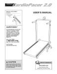
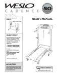
®
®
Model No. WCTL81590
Serial No.
USER'S MANUAL
Serial Number Decal
QUESTIONS?
As a manufacturer, we are committed to providing complete
customer satisfaction. If you
have questions, or find that there
are missing or damaged parts,
we will guarantee you complete
satisfaction through direct assistance from our factory.
TO AVOID UNNECESSARY
DELAYS, PLEASE CALL DIRECT
TO OUR TOLL-FREE CUSTOMER
HOT LINE. The trained technicians on our Customer Hot Line
will provide immediate assistance, free of charge to you.
CUSTOMER HOT LINE:
1-888-936-4266
Mon.–Fri., 8 a.m.–6:30 p.m. EST
CAUTION
Read all precautions and instructions in this manual before using
this equipment. Save this
manual for future reference.
www.weslo.com
TABLE OF CONTENTS
IMPORTANT PRECAUTIONS . . . . . . . . . . . . . . . . . . . . . . . . . . . . . . . . . . . . . . . . . . . . . . . . . . . . . . . . . . . . . . . . .2
BEFORE YOU BEGIN . . . . . . . . . . . . . . . . . . . . . . . . . . . . . . . . . . . . . . . . . . . . . . . . . . . . . . . . . . . . . . . . . . . . . . .4
ASSEMBLY . . . . . . . . . . . . . . . . . . . . . . . . . . . . . . . . . . . . . . . . . . . . . . . . . . . . . . . . . . . . . . . . . . . . . . . . . . . . . . .5
PROPER EXERCISE FORM . . . . . . . . . . . . . . . . . . . . . . . . . . . . . . . . . . . . . . . . . . . . . . . . . . . . . . . . . . . . . . . . . .6
OPERATION AND ADJUSTMENT . . . . . . . . . . . . . . . . . . . . . . . . . . . . . . . . . . . . . . . . . . . . . . . . . . . . . . . . . . . . .7
TROUBLE-SHOOTING AND STORAGE . . . . . . . . . . . . . . . . . . . . . . . . . . . . . . . . . . . . . . . . . . . . . . . . . . . . . . . .10
CONDITIONING GUIDELINES . . . . . . . . . . . . . . . . . . . . . . . . . . . . . . . . . . . . . . . . . . . . . . . . . . . . . . . . . . . . . . .12
PART LIST . . . . . . . . . . . . . . . . . . . . . . . . . . . . . . . . . . . . . . . . . . . . . . . . . . . . . . . . . . . . . . . . . . . . . . . . . . . . . . .14
EXPLODED DRAWING . . . . . . . . . . . . . . . . . . . . . . . . . . . . . . . . . . . . . . . . . . . . . . . . . . . . . . . . . . . . . . . . . . . . .15
ORDERING REPLACEMENT PARTS . . . . . . . . . . . . . . . . . . . . . . . . . . . . . . . . . . . . . . . . . . . . . . . . . . . . . . . . . .16
LIMITED WARRANTY . . . . . . . . . . . . . . . . . . . . . . . . . . . . . . . . . . . . . . . . . . . . . . . . . . . . . . . . . . . . . . . . . . . . . .16
CUSTOMER RECORD . . . . . . . . . . . . . . . . . . . . . . . . . . . . . . . . . . . . . . . . . . . . . . . . . . . . . . . . . . . . . . . . . . . . .17
WARRANTY REGISTRATION CARD . . . . . . . . . . . . . . . . . . . . . . . . . . . . . . . . . . . . . . . . . . . . . . . . . . . . . . . . . .18
IMPORTANT PRECAUTIONS
WARNING:
To reduce the risk of burns, fire, electric shock or injury to persons, read the
following important precautions and information before operating the treadmill.
1. It is the responsibility of the owner to ensure
that all users of this treadmill are adequately
informed of all warnings and precautions.
5. Do not operate the treadmill where aerosol
products are used or where oxygen is being
administered.
2. Use the treadmill only as described in this
manual.
6. Keep children under the age of 12 and pets
away from the treadmill at all times.
3. Place the treadmill on a level surface, with
eight feet of clearance behind it. Do not place
the treadmill on any surface that blocks air
openings. To protect the floor or carpet from
damage, place a mat under the treadmill. Do
not place objects under the treadmill to
change the incline.
7. The treadmill should be used only by persons weighing 250 pounds or less. Never
allow more than one person on the treadmill
at a time.
4. Keep the treadmill indoors, away from moisture and dust. Do not put the treadmill in a
garage or covered patio, or near water.
2
8. When connecting the power cord (see HOW
TO PLUG IN THE POWER CORD on page 7),
plug the power cord into a surge protector
(not included) and plug the surge protector
into a grounded circuit capable of carrying
15 or more amps. No other appliance should
be on the same circuit.
9. Use only a CUL-listed surge protector, rated
at 15 amps, with a 14-gauge cord of five feet
or less in length. Do not use an extension
cord.
10. Keep the power cord and the surge protector
away from heated surfaces.
11. Never move the walking belt while the power
is turned off. Do not operate the treadmill if
the power cord or plug is damaged, or if the
treadmill is not working properly. (See
BEFORE YOU BEGIN on page 4 if the treadmill is not working properly.)
12. The roller guards must be 1/8 inch from the
rear roller. Remove the key and adjust the
roller guards, if necessary.
13. Wear appropriate exercise attire when using
the treadmill. Do not wear loose clothing that
could become caught in the treadmill.
Athletic support clothes are recommended
for both men and women. Always wear athletic shoes. Never use the treadmill with bare
feet, wearing only stockings, or in sandals.
14. Never start the treadmill while you are standing on the walking belt.
15. Always hold the handrails while exercising
on the treadmill.
16. Adjust the speed in small increments.
17. To reduce the possibility of the treadmill
overheating, do not operate the treadmill
continuously for longer than 1 hour.
18. Never leave the treadmill unattended while it
is running. Always remove the key when the
treadmill is not in use.
19. The pulse sensor is not a medical device.
Various factors, including the user's movement, may affect the accuracy of heart rate
readings. The pulse sensor is intended only
as an exercise aid in determining heart rate
trends in general.
20. Inspect and tighten all parts of the treadmill
every three months.
21. To change the incline level of the treadmill,
refer to the instructions on page 9. Do not
attempt to change the incline level in any
other way.
22. Never drop or insert any object into any
opening.
23. Always unplug the power cord before performing the maintenance and adjustment
procedures described in this manual. Never
remove the motor hood unless instructed to
do so by an authorized service representative. Servicing other than the procedures in
this manual should be performed by an
authorized service representative only.
24. This treadmill is intended for in-home use
only. Do not use this treadmill in any commercial, rental, or institutional setting.
WARNING:
Before beginning this or any exercise program, consult your physician. This
is especially important for persons over the age of 35 or persons with pre-existing health problems.
Read all instructions before using. ICON assumes no responsibility for personal injury or property
damage sustained by or through the use of this product.
SAVE THESE INSTRUCTIONS
3
BEFORE YOU BEGIN
Thank you for selecting the WESLO CADENCE® 815
treadmill. The natural motion and versatility of treadmills have made them the most popular way to get an
effective cardiovascular workout. The CADENCE 815
treadmill blends advanced technology with innovative
design to let you enjoy this effective exercise in the
convenience and privacy of your home. Feel better,
look better, and be healthier in just a few minutes a
day.
For your benefit, read this manual carefully before
using the treadmill. If you have additional questions,
please call our Customer Service Department toll-free
at 1-888-936-4266, Monday through Friday, 8 a.m.
until 6:30 p.m. Eastern Standard Time (excluding holidays). To help us assist you, please note the product
model number and serial number before calling. The
model number is WCTL81590. The serial number can
be found on a decal attached to the treadmill (see the
front cover of this manual for the location).
Before reading further, please review the drawing
below and familiarize yourself with the parts that are
labeled.
Console
Towel Rack
Pulse Sensor
Speed Control
Key/Clip
Upright
Handrails
FRONT
Circuit Breaker
Motor Hood
Walking Belt
Power Cord
Roller Guards
Incline Pin
BACK
Foot Rail
RIGHT SIDE
Rear Roller
Adjustment Bolt
4
ASSEMBLY
Set the treadmill in a cleared area and remove all packing materials. Do not dispose of the packing materials until
assembly is completed. Refer to the drawings below to identify small parts used in assembly. Assembly requires
an adjustable wrench
(not included).
3/8" x 1" Bolt (18)–1
3/8" x 1 1/2" Washer
(28)–1
3/8" Flange Nut (48)–2
3/8" x 2 3/4" Bolt (49)–2
3/8" x 1 3/4" Bolt (2)–2
1. Raise the Upright (11) to the vertical position. Insert the 3/8” x 1”
Bolt (18) and the 3/8” x 1 1/2” Washer (28) into the lower end of
the Upright. Finger tighten the Bolt into the Frame (59).
1
11
18
28
59
2. Hold the upper end of the Right Handrail (10) under the
Console (3). Insert a 3/8” x 1 3/4” Bolt (2) up into the Handrail,
and finger tighten the Bolt into the plate under the Console.
2
3
1
Attach the Left Handrail (1) in the same manner.
2
10
3. Insert a 3/8” x 2 3/4” Bolt (49) into the lower end of the Right
Handrail (10) and through the Frame (59). Reach under the
Frame and tighten a 3/8” Flange Nut (48) onto the Bolt.
3
59
Attach the Left Handrail (not shown) in the same manner.
10
Tighten all Bolts used in steps 1 and 2.
49
48
4. Remove the paper backing from the Adhesive Clip (64). Press
the Adhesive Clip onto the Right Endcap (63) in the indicated
location. Press the 3/16” Allen Wrench (65) into the Adhesive
Clip.
4
63
64
65
5
5. The Console (3) requires two "AA" batteries (not included).
Alkaline batteries are recommended.
5
15
3
Slide the Battery Cover (15) up as shown. Press two batteries into
the battery compartment, with the negative (–) ends of the batteries
touching the springs. Close the battery cover.
Batteries
6. Make sure that all parts are tightened before you use the treadmill. Note: To protect the floor or carpet from
damage, place a mat beneath the treadmill.
PROPER EXERCISE FORM
The instructions on pages 7 to 9 of this manual explain the operation and adjustment of the treadmill. For maximum treadmill performance, it is important to maintain proper form when walking on the treadmill. The drawing
below demonstrates the proper form. Be sure to remember the following important guidelines:
• Always hold the handrails when stepping on
and off the treadmill, and when exercising on
the treadmill.
• Always stand on the foot rails when turning on
the power or starting the walking belt. The walking belt may not start while you are standing on it.
• While walking on the treadmill, rest your hands
on the handrail, keep your back straight, and
lean forward slightly. Do not lean back or push
forward against the walking belt with your feet. If
you slow the walking belt with your feet, it may
come to a stop. If this happens, stand on the foot
rails until the walking begins to move again.
• To change the incline level of the treadmill,
refer to page 9. Do not attempt to change the
incline level any other way. The incline range of
the treadmill is 11% to 14%. This range is ideal for
maximum treadmill performance.
6
OPERATION AND ADJUSTMENT
THE PERFORMANT LUBETM WALKING BELT
Your treadmill features a walking belt coated with
PERFORMANT LUBETM, a high-performance lubricant.
IMPORTANT: Never apply silicone spray or other
substances to the walking belt or the walking platform. They will deteriorate the walking belt and
cause excessive wear.
HOW TO PLUG IN THE POWER CORD
DANGER:
Improper connection
of the equipment-grounding conductor can
result in an increased risk of electric shock.
Check with a qualified electrician or serviceman if you are in doubt as to whether the
product is properly grounded. Do not modify
the plug provided with the product—if it will
not fit the outlet, have a proper outlet
installed by a qualified electrician.
risk of electric shock. This product is equipped with a
cord having an equipment-grounding conductor and a
grounding plug. Plug the power cord into a surge
protector, and plug the surge protector into an
appropriate outlet that is properly installed and
grounded in accordance with all local codes and
ordinances.
This product is for use on a nominal 120-volt circuit,
and has a grounding plug that looks like the plug illustrated in drawing 1 below. A temporary adapter that
looks like the adapter illustrated in drawing 2 may be
used to connect the surge protector to a 2-pole receptacle as shown in drawing 2 if a properly grounded outlet is not available.
The temporary adapter should be used only until a
properly grounded outlet (drawing 1) can be installed
by a qualified electrician.
The green-colored rigid ear, lug, or the like extending
from the adapter must be connected to a permanent
ground such as a properly grounded outlet box cover.
Whenever the adapter is used it must be held in place
by a metal screw. Some 2-pole receptacle outlet box
covers are not grounded. Contact a qualified electrician to determine if the outlet box cover is
grounded before using an adapter.
Your treadmill, like any other type of sophisticated
electronic equipment, can be seriously damaged by
sudden voltage changes in your home’s power.
Voltage surges, spikes, and noise interference can
result from weather conditions or from other appliances being turned on
or off. To decrease the
1
possibility of your
Grounded Outlet Box
treadmill being damTreadmill Power Cord
aged, always use a
Grounding Pin
surge protector (not
Grounding
included) with your
Plug
Grounding
treadmill.
Pin
Surge protectors are
Grounding
sold at most hardware
Plug
stores and department
Grounded Outlet
stores. Use only a CULlisted surge protector,
2
Grounded Outlet Box
rated at 15 amps, with a
14-gauge cord of five
Adapter
feet or less in length.
Grounding Pin
This product must be
Grounding
grounded. If it should
Surge Protector
Plug
malfunction or break
down, grounding proLug
vides a path of least
resistance for electric
Metal Screw
current to reduce the
7
DIAGRAM OF THE CONSOLE
On/Off
Button
Note: If there is a thin sheet of clear
plastic on the console, remove it.
Scan
Button
Clip
Key
CAUTION: Before operating the con-
1
sole, read the following important precautions.
• Always wear the clip while operating the treadmill. When the key is removed from the console, the power will shut off.
• After the speed control is moved, there will be
a pause before the walking belt begins to move.
• To reduce the risk of electric shock, keep the
console dry. Avoid spilling liquid on the console and use only a sealed water bottle.
STEP BY STEP CONSOLE OPERATION
Make sure that the power cord is properly plugged in
(see HOW TO PLUG IN THE POWER CORD on page
7). Next, step onto the foot rails of the treadmill. Find
the clip attached to the key (see the drawing above).
Slide the clip onto your waistband. Follow the steps on
pages 8 and 9 to operate the console.
Insert the key fully into the power switch.
Key
2
Press the ON/OFF button.
The two displays
will appear. Note:
If batteries were
just installed, the
displays will
already appear.
• Adjust the speed in small increments until you
are familiar with the treadmill.
• The training zones marked above the speed
control are guidelines only. Read CONDITIONING GUIDELINES on pages 12 and 13 to determine the proper exercise level.
Pulse Sensor
Note: The two displays will not
appear when the
key is first inserted.
• Do not stand on the walking belt when turning
on the power.
8
Pulse Display
Monitor Display
Speed Control
3
Reset the speed control and start the walking
belt.
Slide the speed
control fully to the
left, to the
"RESET" position.
Next, slide the
control to the right
until the walking
belt begins to
move at a slow speed.
Carefully step onto the walking belt and begin walking. Change the speed of the walking belt as
desired by sliding the speed control. Note: To stop
the walking belt, slide the speed control to the
"RESET" position.
4
this level. After 5 to 10 seconds, your pulse will be
displayed. Hold your thumb on the sensor for
another 15 seconds for the most accurate reading.
If the displayed pulse appears to be too high or too
low, or if your pulse is not displayed, lift your thumb
off the sensor and allow the display to reset. Press
down again on the sensor as described above.
Make sure that your thumb is positioned as shown,
and that you are applying the proper amount of
pressure. Try the sensor several times until you
become familiar with it. Always stand still while
measuring your pulse.
Press the MODE button to select the desired
monitor mode.
The monitor offers
five different modes
to provide instant
exercise feedback:
SPEED—displays
your speed, in miles
per hour.
Mode
Indicators
TIME—displays the elapsed time.
6
DISTANCE—displays the distance that you have
walked or run, in miles.
CALORIES—displays the approximate number of
Calories you have burned. Note: The actual number
of Calories you have burned may differ slightly from
the number displayed if the speed or incline is near
the lowest or highest setting.
SCAN—displays the SPEED, TIME, DISTANCE,
and CALORIES modes, for five seconds each, in a
repeating cycle.
When the power is turned on, the SCAN mode will
automatically be selected. One mode indicator (see
the drawing above), will appear by the scan symbol,
and a second mode indicator will show which mode
is currently displayed.
If desired, the SPEED, TIME, DISTANCE or
CALORIES mode can be displayed continuously.
Press the MODE button repeatedly until the mode
indicator by the scan symbol disappears, and a mode
indicator appears by the symbol of the desired
mode.
Note: The monitor displays can be reset by pressing the on/off button twice.
5
Measure your pulse, if desired.
To use the pulse
sensor, stand on the
Pulse Sensor
foot rails and place
your thumb on the
pulse sensor as
shown. The pulse
sensor is pressureactivated. Fully
press down the
pulse sensor. Do not press too hard, or the circulation in your thumb will be restricted, and your
pulse will not be detected. Next, slightly raise
your thumb until the heart-shaped indicator in the
pulse display flashes steadily. Hold your thumb at
When you are finished, stop the walking belt
and remove the key.
Slide the speed control to the “RESET” position,
and remove the key. Store the key in a secure location.
7
Press the ON/OFF button.
To turn off the displays, press the on/off button.
Note: If the walking belt is stopped and the console
buttons are not pressed for 3 to 6 minutes, the displays will turn off automatically.
HOW TO CHANGE THE INCLINE OF THE TREADMILL
To vary the intensity
of your exercise, the
incline of the treadmill can be
changed. There are
three different
incline levels.
Before changing
the incline, remove
the key and
unplug the power
cord.
1
Incline Pin
Frame
Incline Leg
2
Incline Pin
To change the
incline, carefully lay
the treadmill on its
left side. Remove the incline pin from the right incline leg
as shown in drawing 1. Adjust the incline leg to the
desired height and fully re-insert the incline pin. Make
sure the incline pin is in the “locked” position shown in
drawing 2. Lay the treadmill on its right side. Repeat the
procedure for the left ifncline leg.
CAUTION: Before using the treadmill, make sure
that both incline pins are fully inserted at the same
height. Do not use the treadmill with the incline pins
removed.
9
TROUBLE-SHOOTING AND STORAGE
Most treadmill problems can be solved by following the simple steps below. Find the symptom that
applies to your treadmill and follow the steps listed. If further assistance is needed, please call our
Customer Service Department toll-free at 1-888-936-4266, Monday through Friday, 8 a.m. until 6:30 p.m.
Eastern Standard Time (excluding holidays).
1. SYMPTOM: THE POWER DOES NOT TURN ON
a. Make sure that the power cord is plugged into a surge protector, and that the surge protector is plugged into
a properly grounded outlet (see HOW TO PLUG IN THE POWER CORD on page 7). Use only a UL-listed
surge protector, rated at 15 amps, with a 14-gauge cord of five feet or less in length.
b. After the power cord has been plugged in, make sure that the key is fully inserted into the console (see step
1 on page 8).
c. Check the circuit breaker located on the treadmill frame near
the power cord. If the switch protrudes as shown, the circuit
breaker has tripped. To reset the circuit breaker, wait for five
minutes and then press the switch back in.
Tripped
2. SYMPTOM: THE POWER TURNS OFF DURING USE
Reset
a. Check the circuit breaker located on the treadmill frame near the power cord. If the circuit breaker has
tripped, the switch will protrude (see the drawing above). To reset the circuit breaker, wait for five minutes
and then press the switch back in.
b. Make sure that the power cord is plugged in.
c. Remove the key from the console. Reinsert the key fully into the console (see Step 1 on page 8).
3. SYMPTOM: THE DISPLAYS OF THE CONSOLE DO NOT FUNCTION PROPERLY
a. Check the batteries in the console (see assembly step 5 on page 6). Most problems are the result of drained
batteries.
b. If the speed display does not show a correct reading, remove
the key and UNPLUG THE POWER CORD. Remove the four
screws from the sides and front of the hood. Carefully remove
the hood. Locate the Reed Switch (73) and the Magnet (75) on
the left side of the Pulley (43). Turn the Pulley until the Magnet
is aligned with the Reed Switch. Make sure that the gap
between the Magnet and the Reed Switch is about 1/8”. If
necessary, loosen the Screw (53) and move the Reed Switch
slightly. Retighten the Screw. Re-attach the hood and run the
treadmill for a few minutes to check for a correct speed reading.
b
1/8”
73
43
75
53
Top
View
4. SYMPTOM: THE WALKING BELT SLOWS OR STOPS WHEN WALKED ON
a. Use only a CUL-listed surge protector, rated at 15 amps, with a 14-gauge cord of five feet or less in length.
b. Increase the incline of the treadmill (see HOW TO CHANGE THE INCLINE OF THE TREADMILL on page 9).
c. Make sure that you are using proper form when walking on the treadmill (see PROPER EXERCISE FORM
on page 6).
d. If the walking belt still slows when walked on, please call our Customer Service Department.
10
5. SYMPTOM: THE WALKING BELT IS OFF-CENTER
a. If the walking belt has shifted to the left, first remove the key and
UNPLUG THE POWER CORD. Using the allen wrench, turn the
rear roller adjustment bolt clockwise 1/4 of a turn. Plug in the
power cord, insert the key and run the treadmill for a few minutes. Repeat until the walking belt is centered.
b. If the walking belt has shifted to the right, first remove the key
and UNPLUG THE POWER CORD. Using the allen wrench, turn
the rear roller adjustment bolt counterclockwise 1/4 of a turn.
Plug in the power cord, insert the key and run the treadmill for a
few minutes. Repeat until the walking belt is centered.
a
b
STORAGE
Unplug the power cord when the treadmill is not in use.
Remove the bolt and nut from the lower end of each handrail.
Remove
Remove the bolt from the upper end of each handrail.
Remove
Remove the bolt and washer from the lower end of the upright. Lay
the upright on the treadmill. Keep all bolts and washers in a
secure location.
Remove
Remove the batteries from the console and cover the treadmill during extended periods of storage.
11
CONDITIONING GUIDELINES
WARNING: Before beginning
Age
Unconditioned
Conditioned
20
138-167
133-162
25
136-166
132-160
30
135-164
130-158
35
134-162
129-156
40
132-161
127-155
45
131-159
125-153
50
129-156
124-150
The following guidelines will help you to plan your exercise program. Remember—these are general guidelines. For more detailed information about exercise,
obtain a reputable book or consult your physician.
55
127-155
122-149
60
126-153
121-147
65
125-151
119-145
EXERCISE INTENSITY
70
123-150
118-144
75
122-147
117-142
80
120-146
115-140
85
118-144
114-139
this or any exercise program, consult your
physician. This is especially important for
individuals over the age of 35 or individuals
with pre-existing health problems.
The pulse sensor is not a medical device.
Various factors, including your movement,
may affect the accuracy of heart rate readings.
The sensor is intended only as an exercise aid
in determining heart rate trends in general.
Whether you want to burn fat or strengthen your cardiovascular system, you can tailor your exercise to
your specific goals. The key to achieving the desired
results is to exercise with the proper intensity.
Burning Fat
To burn fat effectively, you must exercise at a relatively
low intensity level for a sustained period of time.
During the first few minutes of exercise, your body
uses easily accessible carbohydrate calories for energy. Only after the first few minutes of exercise does
your body begin to use stored fat calories for energy.
If your goal is to burn fat, set the speed control on the
console to the turtle symbol (
) to help you maintain
the proper intensity level (see page 8).
Aerobic Exercise
12
Training Zone (Beats/Min.)
If your goal is to strengthen your cardiovascular system, your exercise must be “aerobic.” Aerobic exercise
is activity that requires large amounts of oxygen for
prolonged periods of time. This increases the demand
on the heart to pump blood to the muscles, and on the
lungs to oxygenate the blood. The proper intensity
level for aerobic exercise can be found by using your
pulse as a guide. As you exercise, your pulse should
be kept at a level between 70% and 85% of your maximum possible heart rate. This is known as your training zone. You can find your training zone in the table
at the top of this page. Training zones are listed
according to age and physical condition. During the
first few months of your exercise program, keep your
pulse near the low end of your training zone as you
exercise. After a few months of regular exercise, your
pulse can be gradually increased until it is near the middle of your training zone as you exercise. You can measure your pulse using the pulse sensor. Exercise for
about four minutes, and then measure your pulse immediately. If your pulse is too high or too low, adjust the
intensity of your exercise. It may also be helpful to set
the speed control on the console halfway between the
turtle symbol (
) and the rabbit symbol (
) to help
you maintain the proper intensity level. (See page 8.)
Performance Training
If your goal is high performance athletic conditioning,
set the speed control on the console to the rabbit symbol (
) to help you maintain the proper intensity level
(see page 8).
WORKOUT GUIDELINES
When exercising, wear appropriate attire. Always wear
athletic shoes for foot protection. Each workout should
include three basic parts: (1) a warm-up, (2) training
zone exercise, and (3) a cool-down.
Warming Up
Warming up prepares the body for exercise by increasing circulation, delivering more oxygen to the muscles
and raising the body temperature. Begin each workout
with 5 to 10 minutes of stretching and light exercise to
warm up (see SUGGESTED STRETCHES on page 13).
Training Zone Exercise
After warming up, increase the intensity of your exercise until your pulse is in your training zone for 20 to
60 minutes. (During the first few weeks of your exercise program, do not keep your pulse in your training
zone for longer than 20 minutes.) Breathe regularly
and deeply as you exercise—never hold your breath.
to cool down. This will increase the flexibility of your
muscles and will help to prevent post-exercise problems.
Exercise Frequency
To maintain or improve your condition, complete three
workouts each week, with at least one day of rest
between workouts. After a few months, you may complete up to five workouts each week if desired.
Cooling Down
Finish each workout with 5 to 10 minutes of stretching
The key to success is to make exercise a regular and
enjoyable part of your everyday life.
SUGGESTED STRETCHES
The correct form for several basic stretches is shown in the
drawings below. Move slowly as you stretch—never bounce.
1
1. Toe Touch Stretch
Stand with your knees bent slightly and slowly bend forward
from your hips. Allow your back and shoulders to relax as you
reach down toward your toes as far as possible. Hold for 15
counts, then relax. Repeat 3 times. Stretches: Hamstrings,
back of knees and back.
2
2. Hamstring Stretch
Sit with one leg extended. Bring the sole of the opposite foot
toward you and rest it against the inner thigh of your extended
leg. Reach toward your toes as far as possible. Hold for 15
counts, then relax. Repeat 3 times for both legs. Stretches:
Hamstrings, lower back and groin.
3
3. Calf/Achilles Stretch
With one leg in front of the other, reach forward and place your
hands against a wall. Keep your back leg straight and your
back foot flat on the floor. Bend your front leg, lean forward
and move your hips toward the wall. Hold for 15 counts, then
relax. Repeat 3 times for both legs. To cause further stretching
of the achilles tendons, bend your back leg as well. Stretches:
Calves, achilles tendons and ankles.
4
4. Quadriceps Stretch
With one hand against a wall for balance, reach back and
grasp one foot with your other hand. Bring your heel as close
to your buttocks as possible. Hold for 15 counts, then relax.
Repeat 3 times for both legs. Stretches: Quadriceps and hip
muscles.
5
5. Inner Thigh Stretch
Sit with the soles of your feet together and your knees outward. Pull your feet toward your groin area as far as possible.
Hold for 15 counts, then relax. Repeat 3 times. Stretches:
Quadriceps and hip muscles.
13
PART LIST—Model No. WCTL81590
Key No.
Qty.
1
2
3*
4
5
6
7
8
9
10
11
12
13
14
15
16
17*
18
19
20
21
22
23
24
25
26
27
28
29
30
31
32
33
34
35
36
37
38
39
40
41
42
43
1
2
1
1
2
5
1
1
1
1
1
1
1
1
1
1
1
2
1
1
1
4
4
6
1
2
1
1
1
1
1
1
1
2
9
2
2
2
2
1
4
1
1
Description
Left Handrail
3/8” x 1 3/4” Bolt
Console
Upright Wire Harness
Console Cage Nut
Console Screw
Pot Wire
Console Cable Loom
Key/Clip
Right Handrail
Upright
Motor Swivel Bolt
Upright Cage Nut
Motor Swivel Nut
Battery Cover
Motor
Motor/Pulley/Flywheel
3/8” x 1” Bolt
Motor Tension Washer
Star Washer
Motor Tension Nut
Wire Clip
Hood Anchor
Anchor Screw
Upright Pivot Nut
Upright Pivot Washer
Upright Cable Loom
3/8” x 1 1/2” Washer
Reed Switch Clip
Power Cord
Circuit Breaker
Upright Pivot Bolt
Grommet
Frame Endcap
Screw
Incline Pin
Incline Leg Cap
Incline Leg
Belt Guide
Front Roller Adjustment Bolt
Adjustment Washer
Safety Cover
Front Roller/Pulley
Key No.
44
45
46
47
48
49
50
51
52
53
54
55
56
57
58
59
60
61
62
63
64
65
66
67
68
69
70
71
72
73
74
75
76
77
78
79
80
81
#
#
#
R0699A
Qty.
1
1
2
1
2
2
1
1
4
9
4
2
1
1
1
1
2
1
1
1
1
1
2
1
1
6
4
1
2
1
1
1
1
1
1
2
2
2
1
1
1
Description
Walking Platform
Walking Belt
Foot Rail
Pulley/Flywheel
3/8” Flange Nut
3/8” x 2 3/4” Bolt
Controller
Controller Plate
Plastic Stand-Off
Small Screw
4” Cable Tie
8” Cable Tie
Tie Holder
Potentiometer
Speed Control
Frame
Rubber Pad
Tension Spring
Roller Ground Wire
Right Endcap
Adhesive Clip
Allen Wrench
Short Roller Adjustment Bolt
Left Endcap
Rear Roller
Platform Screw
Hood Screw
Hood
Roller Guard Screw
Reed Switch/Sensor Wire
Roller Tension Nut
Magnet
Motor Belt
Motor Fan
Long Roller Adjustment Bolt
Roller Guard
Handgrip
3/8” Cap Washer
8” Green Ground Wire
8” White Wire, Male/Female
User’s Manual
* Includes all the parts in the box.
# Indicates a non-illustrated part.
Specifications are subject to change without notice. See the back cover for information about ordering replacement parts.
14
EXPLODED DRAWING—Model No. WCTL81590
R0699A
58
15
57
3*
4
6
2
5
6
1
18
80
9
7
20
21
14
8 5
6
19
2
17*
6
10
71
47
11
16
77
70
70
12
25
18
26
22
53
73
29
27
26
24
23
28
30
31
32
76
75
33
49
70
48
43
41
42
40
34
44
35
46
69
41 74
72
13
46
45
39
61
38
36
79
67
53
72
68
66
48
41
37
49
59
60
53
63
41
78
64
65
81
24
62
53
51
53
56
50
55
52
54
15
ORDERING REPLACEMENT PARTS
To order replacement parts, call our Customer Service Department toll-free at 1-888-936-4266, Monday through
Friday, 8 a.m. until 6:30 p.m. Eastern Standard Time (excluding holidays). When ordering parts, please be prepared to give the following information:
• The MODEL NUMBER of the product (WCTL81590)
• The NAME of the product (WESLO CADENCE® 815 treadmill)
• The SERIAL NUMBER of the product (see the front cover of this manual)
• The KEY NUMBER of the part(s) (see page 14 of this manual)
• The DESCRIPTION of the part(s) (see page 14 of this manual).
LIMITED WARRANTY
ICON OF/DU CANADA INC., (ICON), warrants this product to be free from defects in workmanship and
material, under normal use and service conditions, for a period of ninety (90) days from the date of purchase.
This warranty extends only to the original purchaser. ICON's obligation under this warranty is limited to
replacing or repairing, at ICON's option, the product at one of its authorized service centers. All products for
which warranty claim is made must be received by ICON at one of its authorized service centers with all
freight and other transportation charges prepaid, accompanied by sufficient proof of purchase. All returns
must be pre-authorized by ICON. This warranty does not extend to any product or damage to a product
caused by or attributable to freight damage, abuse, misuse, improper or abnormal usage or repairs not provided by an ICON authorized service center, to products used for commercial or rental purposes, or to products used as store display models. No other warranty beyond that specifically set forth above is authorized by
ICON.
ICON is not responsible or liable for indirect, special or consequential damages arising out of or in connection
with the use or performance of the product or damages with respect to any economic loss, loss of property,
loss of revenues or profits, loss of enjoyment or use, costs of removal, installation or other consequential
damages of whatsoever nature. Some provinces do not allow the exclusion or limitation of incidental or consequential damages. Accordingly, the above limitation may not apply to you. The warranty extended hereunder is in lieu of any and all other warranties and any implied warranties of merchantability or fitness for a particular purpose is limited in its scope and duration to the terms set forth herein. Some provinces do not allow
limitations on how long an implied warranty lasts. Accordingly, the above limitation may not apply to you.
The warranty extended hereunder is in lieu of any and all other warranties and any implied warranties of merchantability or fitness for a particular purpose is limited in its scope and duration to the terms set forth herein.
This warranty gives you specific legal rights. You may also have other rights which vary from province to
province or so specified by the retailer of your equipment.
ICON OF/DU CANADA, 900 de l’Industrie, St-Jérôme, QC J7Y 4B8
16
CUSTOMER RECORD
Model No.:
Serial No.:
Retailer Name:
Purchase Date:
Retailer Address:
PLACE
STAMP
HERE
ICON of Canada Inc.
900 de l’Industrie
St-Jérôme, Québec
Canada, J7Y 4B8
17
™
®
PRODUCT WARRANTY REGISTRATION
of/du Canada Inc.
IMPORTANT: MAIL WITHIN 14 DAYS OF PURCHASE
NAME:
PHONE:
ADDRESS:
POSTCODE:
COUNTY:
MODEL NO.
SERIAL NO.
PURCHASE DATE:
RETAILER ADDRESS:
RETAILER NAME:
1) Primary user(s) of product:
❏ Male
❏ Female
❏ Family
2) Age of primary user:
❏ 0–24
❏ 25–34
❏ 55–64
❏ 65 and over
❏ 35–44
❏ 45–54
3) Annual household income:
❏ 0–9,999
❏ 15,000–19,999
❏ 10,000–14,999
❏ 20,000+
4) How many times a week do you exercise?
❏ Less than 3 times ❏ 3 times or more
5) Have you ever purchased an ICON product before?
❏ Yes
❏ No
6) Where did you first see or hear about ICON products?
❏ Magazine
❏ Friend/relative
❏ Newspaper Ad
❏ Store
❏ Other
7) What was the primary reason for purchasing this ICON product?
❏ Store Employee
❏ Television Ads ❏ Colour
❏ Electronic Features ❏ Magazine Ads ❏ Price
❏ Product Design
❏ Product Innovation
❏ Other Features
8) Did you consider purchasing fitness equipment from another
manufacturer?
❏ No
❏ Yes
What other Manufacturer?
9) Based on your impression of what you have purchased,
would you buy another ICON product?
❏ Yes
❏ No
❏ No Opinion
If not, what other brand name equipment would you purchase?
10) What other type of exercise equipment do you own?
❏ Bicycle
❏ Exercise Cycle ❏ Treadmill
❏ Home Gym
❏ Weight Bench ❏ Stepper
❏ Cardio Glide
❏ Other
11) Which type of magazines do you read regularly?
❏ Sports
❏ Fitness
❏ Motoring
❏ Business
❏ Computer
❏ General
12) Do you wish to be sent further bulletins about ICON products?
❏ Yes
❏ No
THANK YOU FOR YOUR TIME
© 1999 ICON of Canada, Inc. Printed in Canada
WESLO is a registered trademark of ICON Health & Fitness, Inc.
18 Part No. 155804 J01451-C R0699A
Printed in Canada © 1999 ICON Health & Fitness, Inc.