1
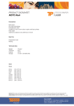
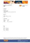
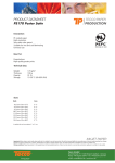
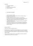
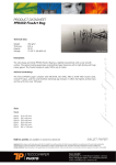
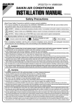
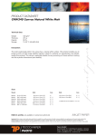
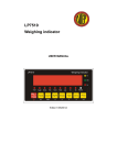
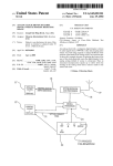
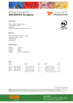
Operating Instructions for
Melt pressure sensor / Melt pressure transmitter
Contents
1.
Ratings..................................................................................................................................3
1.1. Type designation ...............................................................................................................3
1.2. Ratings ..............................................................................................................................4
1.3. Electrical connections........................................................................................................5
1.3.1. Melt pressure sensor, mV / V .....................................................................................5
1.3.2. Melt pressure transmitter, 2-conductor 4-20 mA ........................................................5
1.3.3. Melt pressure transmitter, 4-conductor 4-20 mA or 0 (2) -10 V ..................................5
1.3.4. Calibration ..................................................................................................................5
2. Safety....................................................................................................................................7
2.1. Indications on work safety .................................................................................................7
2.2. Dangerous spots ...............................................................................................................7
2.3. Disposal.............................................................................................................................8
2.4. Information on environmental protection ...........................................................................8
3. General .................................................................................................................................9
3.1. Introduction........................................................................................................................9
3.2. Field of employment / application ......................................................................................9
4. Transport.............................................................................................................................10
4.1. Packing............................................................................................................................10
4.2. Sensitivity ........................................................................................................................10
4.3. Intermediate stocking and scope of delivery....................................................................10
5. Design and Operation .........................................................................................................11
5.1. Operation.........................................................................................................................11
6. Mounting and first operation................................................................................................12
6.1. Measures to be taken prior to mounting ..........................................................................12
6.2. Mounting..........................................................................................................................12
6.3. Dismounting.....................................................................................................................12
6.4. Measures to be taken prior to first operation ...................................................................13
6.5. First operation..................................................................................................................13
7. Operation and maintenance................................................................................................14
7.1. Operation.........................................................................................................................14
7.2. Maintenance ....................................................................................................................14
8. Repairing and Service.........................................................................................................15
8.1. General............................................................................................................................15
8.2. Addresses .......................................................................................................................15
8.3. Others..............................................................................................................................15
8.4. Copyright .........................................................................................................................15
8.5. Revision...........................................................................................................................15
S-MDGB.DOC / status 03/2006
Seite 2/15
Safety
1. Ratings
1.1. Type designation
S–MD–st–u–vwxy–z
Spacer
Technical execution
s
1
2
Connecting thread
½ ‘‘ 20 UNF 2A
M18 x 1,5
1
2
3
4
Shaft length
152 mm rigid
250 mm rigid
318 mm rigid
152 mm rigid + 457 mm flexible capillary tubes
50
100
200
350
400
500
600
700
800
1000
Pressure range
0...50 bar
0...100 bar
0...200 bar
0...350 bar
0...400 bar
0...500 bar
0...600 bar
0...700 bar
0...800 bar
0...1000 bar
1
2
Transfer medium
NaK-liquid metal
Mercury
1
2
Precision
+/- 0,5 % of final value
+/- 1 % of final value
t
u
v
w
x
5
Sensitivity / Analogue output
1 mV/V
2 mV/V
3,33 mV/V
4 - 20 mA / 2-conductor
0 - 10 V / 4-conductor
2 - 10 V / 4-conductor
4 - 20 mA / 4-conductor
Type of material of diaphragm
stainless steel, material no. 1.4545, coated with TiN ceramics
Hastelloy, material no. 2.4610, coated with TiN ceramics
Inconel, material no. 2.4668,coated with TiN ceramics
reinforced diaphragm of stainless steel, material no. 1.4545, coated with TIN
ceramics
reinforced diaphragm of Inconel, material no. 2.4668, coated with TiN ceramics
0
Options
Options are not defined.
1
2
3
4
5
6
4.4
y
1
2
3
4
z
S-MDGB.DOC / status 03/2006
Seite 3/15
Safety
1.2. Ratings
Model:
S-MD-xx-x-1 / S-MD-xx-x-2
Filling medium:
Mercury / Sodium- Potassium (NaK)
max. diaphragm temperature:
400°C / 550°C
Pressure range:
0 - 50 ...0 -2000 bar / 0 - 50 ...0 -700 bar
max. overload:
1.5 x measuring range up to 1000 bar
1.25 x measuring range bigger than 1000 bar
Total measuring error:
≤ 0.5 % of fullscale or ≤ 1 %
Resolution:
infinite
Bridge resistance:
350 Ohm ± 3%
Supply voltage:
with all mV/V signals: max. 12 VDC
with analogue output 4: 12 ... 30 VDC
with analogue output 4.4: 24 VDC ± 10 %
Null balance:
± 5 % of fullscale
Output signal:
1 / 2 / 3.33 mV / V ± 3%
0 (2)...10 V
4 - 20 mA
Internal calibration point:
80%
Reproducibility:
± 0.20 % of fullscale / ± 0.20 % F. S.
Temperature influences at the diaphragm:
Change of zero point:
≤ ± 0.015 % of fullscale / K
Change of sensitivity:
≤ ± 0.010 % of fullscale / K
Temperature influences at the measuring head:
Change of zero point:
≤ ± 0.020 % of fullscale / K / ≤ ± 0.03 % of fullscale
Change of sensitivity:
Measuring range / range ≥ 100 bar 0.02 % / K
Measuring range / range ≥ 50 bar 0.03 % / K
S-MDGB.DOC / status 03/2006
Seite 4/15
Safety
1.3. Electrical connections
1.3.1. Melt pressure sensor, mV / V
Connecting plug:
Bendix PT 02A - 10 - 6P
Counter plug:
Bendix PT 06W - 10 - 6S
A
F
B
E
C
D
A
B
C
D
E
F
signal +
signal –
supply +
supply – / calibration –
supply – / calibration –
calibration +
Illustration 1
1.3.2.
Melt pressure transmitter, 2-conductor 4-20 mA
Connecting plug:
Counter plug:
Bendix PT 02A - 10 - 6P
Bendix PT 06W - 10 - 6S
A
F
B
E
C
D
A
B
C
D
E
F
signal + (supply +)
signal – (supply –)
open
open
calibartion +
calibartion –
Illustration 2
1.3.3.
Melt pressure transmitter, 4-conductor 4-20 mA or 0 (2) -10 V
Connecting plug:
Counter plug:
Bendix PT 02A - 10 - 6P
Bendix PT 06W - 10 - 6S
A
F
B
E
D
C
A
B
C
D
E
F
signal +
signal –
supply + / calibration +
supply –
open
calibration –
Illustration 3
1.3.4. Calibration
By using the calibration the sensor is set to 80% of its fullscale value.
The 80% signal on the output is applied when the connections „calibration +“ and
„calibration –“ are connected by using a floating contact.
S-MDGB.DOC / status 03/2006
Seite 5/15
Safety
235,00"
73,00"
152,00" (= L)
C
B 4 5,00°
-0,15"
- 0,1"
+ 0,0"
ø d2
ø d1
D
-0,05"
ø d3
S W 19
+0,00"
ø 36
A
+ -0 ,05 "
722
73,00"
(23,00")
4 57 (= Lf)
15 2,0 0"(= L )
C
B 4 5 ,00 °
+ -0,05"
- 0,1"
+0,0"
ø d1
D
-0,05"
ø d2
SW
+0,00"
-0,15"
ø d3
ø 22
\U +22058
ø 36
A
3 00
30,50"
B
45
+-0 ,05 "
,0 0
ø d2
2 0,5 0"
-0,15"
D
1,60"
°
SW
ø d1
ø 22
\ U +22058
ø 36
A
+ 0,0 "
15,00"
-0,1"
626 (= L f)
+ 0,0 0"
(23 ,00 ")
- 0,0 5"
722
73,00"
D
A
1/2" 20 UNF 5.6
6
M 18 x 1,5
-0,05-0,15
0-0,20
B
C
11
14
17
19
d1
d2
7.8
10
10.5
16
0-0,05
0-0,05
0-0,05
0-0,10
d3
L*
Lf #
SW
12.7
18
152
457
17
19
L* optional length 250, 320, 450 ..., or according to dimensional indication
Lf # optional length 510, 750, 1000 ..., or according to dimensional indication
Illustration 4
S-MDGB.DOC / status 03/2006
Seite 6/15
Safety
2. Safety
2.1. Indications on work safety
• The pressure sensor has been built in accordance with the latest technology and allows for
•
•
•
•
•
•
•
•
•
safe operation.
The pressure sensor has been designed exclusively for the sensing of pressures of the
media mentioned in the chapter 3.2. Any other use of the sensor beyond this is considered to
be out of designation. The manufacturer will not be liable for any damages resulting from
such unauthorised use and the risk has to be borne solely by the user.
The definition of the use of the sensor in accordance with its designation also includes the
observance of the Operating Instructions considered imperative by the manufacturer:
mounting and dismounting as well as the conditions for first operation and use. In addition,
the sensor itself must be handled with the required care.
The pressure sensor must only be used and employed by authorised and correspondingly
instructed persons strictly observing all information, data and indications in these Operating
Instructions.
Any operation impairing the safety of the pressure sensor must be avoided.
The operator has to take care that only authorised persons work on the machine equipped
with the pressure sensor.
The operator is obliged to inform the supervisory personnel immediately about any changes
on the pressure sensor which may impair safety.
Unauthorised changes and modifications which may impair the safety and use of the
pressure sensor are not permitted.
In accordance with the corresponding rules and regulations, the user must make sure the
operating personnel is provided with the required personal safety equipment and makes use
of it.
In the first place, this refers to the wearing of protective gloves with all work activities on the
melt pressure sensor when it has reached its operating temperature. It is imperative to wear
protective gloves when mounting or dismounting the pressure sensor to avoid being burned.
2.2. Dangerous spots
There is danger of burning in the whole area of the heated pressure sensor.
Defective mounting, or dismounting of the pressure sensor with the system being under
pressure may cause the hot media to be sprayed out under high pressure.
When the sensor is not screwed in completely over its whole thread, there is the danger of the
high pressure catapulting the sensor out of its seat.
Check the functionality of the melt pressure sensor at regular intervals to avoid any danger of
excessive rise of pressure, during operation.
Due to technical requirements, the pressure sensor is filled with the pressure transmission
media mercury or NaK. With mercury, the filling quantity amounts to a maximum of 0.25 grams.
The toxic effect of mercury requires to take suitable measures against accidental leaking in
order to avoid the presence of a highly-concentrated mercury vapour (sufficient ventilation...).
With regard to this, please refer to the valid Regulations for the Prevention of Accidents. NaK is
a highly reactive alloy burning away when in contact with the atmosphere. The filling quantity of
NaK amounts to a maximum of 0.02 grams. Sensors filled with NaK are allowed to be used in
the food industry. It is strictly forbidden to use pressure sensors with NaK fillings in areas
with explosion hazard.
S-MDGB.DOC / status 03/2006
Seite 7/15
Safety
2.3. Disposal
In the case of sensors filled with mercury care must be taken that, after potential damaging of
the diaphragm, the liquid is prevented from leaking by screwing on a protective cap. After this,
the sensor must undergo a special waste treatment. You can send the sensor to the
manufacturer who will dispose in accordance of the hazardous waste material. We also
recommend to send sensors with NaK fillings back to the manufacturer although, in these
cases, no special measures have to be taken.
2.4. Information on environmental protection
Manufacturing of the sensors is effected without using any substances damaging the ozone
layer like e.g. CFC, CKW, etc. With the help of modern production methods, the use of energy,
material and auxiliary substances is reduced to a minimum. There are no toxic or ground-water
polluting residues left after the production process. Being a part of our company philosophy,
orderly waste disposal is taken special care of in accordance with the valid laws and
regulations.
S-MDGB.DOC / status 03/2006
Seite 8/15
General
3. General
3.1. Introduction
These Operating Instructions have been prepared in order to be read, understood, and
completely observed in all parts by those persons responsible for the pressure sensor.
The whole technical documentation is to be kept permanently in the immediate work area.
Important details are given in the operationing instructions for the use of the sensor.
Only those persons having read and understood the Operating Instructions can avoid sensor
disturbances and errors with the operation of the sensor, and can ensure a disturbance-free
operation of the sensor. Therefore, it is of utmost importance that the responsible persons
adequately familiar with the content of the present Operating Instructions.
Since we do not take any liability for damages and operating disturbances, The manufacturer
assumes that the Operating Instructions will have been carefully studied prior to the first
operation of the pressure sensor. Nonetheless, if you have any difficulties with the sensor,
please directly contact our engineering department which will be happy to help you with the
solution of the problem.
The information in the Operating Instructions exclusively refer to the type of sensor indicated in
the chapter "1” Ratings".
With regard to the illustrations and data given in the Operating Instructions, the manufacturer
reserves the right to effect technical modifications required to improve the design of the sensor
and to adapt to the latest engineering standards.
3.2. Field of employment / application
This melt pressure sensor/transmitter was exclusively designed to sensor pressure values of
liquid, doughy, or pasty masses of high temperatures. These masses must have a homogenous
consistency and must not have a high share of solid matter. In addition, the mounting location
must be chosen in a way that the maximum differential pressure of 2 % of the measuring range
with reference to the surface of the diaphragm is not exceeded. With the strict exception of NaK
sensors, sensors can also be used in areas with explosion hazard, if permitted and when
employing corresponding connecting devices. However, this is only possible if the connecting
devices are approved and the sensors are suitable for this type of application.
The use in food industry is only permitted if the sensor filling complies with the corresponding
regulations. Any use beyond the field of application is considered to be out of designation.
Any other use of the sensor beyond the field of application is considered to be out of
designation. The manufacturer will not be liable for any damages resulting from such
unauthorised use and the risk has to be borne solely by the user.
Please note that it is imperative to contact our engineering department prior to any use of the
pressure sensor outside its defined field of application since, otherwise, warranty will expire
immediately.
S-MDGB.DOC / status 03/2006
Seite 9/15
Transport
4. Transport
4.1. Packing
A decisive factor for the type of packing used is the way and type of transport. If not agreed
otherwise, the sensors are packed in cardboard boxes.
Components particularly sensitive to shock etc. are additionally equipped with special protective
caps.
4.2. Sensitivity
When transporting sensors, special care has to be taken in order to avoid any damaging with
loading and unloading. As a special protective means for the frontal separating diaphragm, an
aluminium cap is screwed on.
Make sure that, during transport, the creation of condensation water due to great temperature
fluctuations will be avoided, and assure that there will be no shock impacts or that any shock
impacts will be dampened by appropriate packing. Handle the device itself with the same care
employed with sensitive electronic units.
4.3. Intermediate stocking and scope of delivery
If the pressure sensor is not used immediately after delivery, it must be stocked intermediately
at a place protected against dust and humidity. Under special circumstances, the standard
packing must be complemented to grant further protection.
Pay special care to the separating diaphragm. Make sure the added protective aluminium cap is
always screwed firmly onto the cleaned sensor by hand.
The scope of delivery is listed in the shipping documents and must be checked for
completeness after reception of the goods. The scope of delivery is agreed upon with ordering
and can be modified correspondingly.
S-MDGB.DOC / status 03/2006
Seite 10/15
Design and operation
5. Design and Operation
5.1. Operation
The design of the pressure sensor is based on a matured and well-approved system used in
thousands of devices. A capillary tube system filled with liquid connects two diaphragms serves
as a pressure transmission medium. The pressure exerted to the separating diaphragm is
transferred without any losses to the liquid column. It propagates to the measuring diaphragm
located at the end of the capillary system and, as a consequence of the pressure load, causes a
deflexion proportional to the pressure value. Wire resistance strain gauges placed onto the
surface of the diaphragm capture the extension of the excursion and change their electrical
resistance correspondingly. The change in resistance is sensed by a Wheatstone bridge to
deliver the result as a measuring signal.
The sensing of the measuring value by means of hydraulic coupling allows for comparatively
high precision since this system follows the idea of mechanical and hydraulic de-coupling of the
pressure sensing and pressure measuring sections. Additionally, the measuring behaviour is
independent from slight deformations at the separating diaphragm. Increases of pressure due to
a heating of the pressure transmission medium and the drift of the zero point and of the
sensitivity combined with this are compensated by the excursion of the separating diaphragm
and/or a sophisticated design. It is obvious that the separating diaphragm has to be designed to
be much more flexible, i.e. thinner than the measuring diaphragm. In order to allow for a long
service life, only special alloys of top quality and, in some case, additional layers of
mechanically resistant material are used.
S-MDGB.DOC / status 03/2006
Seite 11/15
Mounting and first operation
6. Mounting and first operation
6.1. Measures to be taken prior to mounting
Please note that the mounting dimensions of the sensor bore must exactly correspond to the
given specification. Moreover, the bore and the pressure sensor must be free from work
residues, dirt, and remainders of molten masses.
The dimensional accuracy of the sensor bore can be verified by means of a test bolt.
A tight sealing depends predominantly on high angular precision, the observance of tolerances
with regard to shape and position of the sealing surfaces, and their excellent surface finishing
quality. For this reason, we also recommend the use of an insertion-type bush with its
rectangular shoulders allowing to be manufactured, and to be replaced easily in the case of
damage.
When there are very high requirements to be made regarding gas tightness with vacuum or inert
gas/reaction gas we recommend to provide the conical sealing surface of the sensor with a
number of sealing tape layers, e.g. Teflon tape as used with sanitary installations.
6.2. Mounting
We recommend that the functionality of the sensor is checked prior to its mounting (see item
1.1).
Please provide the sensor connection thread with a heat-resisting separating agent to facilitate
tight fastening of the sensor and to prevent the thread from seizing. When being inserted into
the bore, the pressure sensor must not be tilted or dropped. The pressure sensor must only be
screwed in by hand. In the case that excessive power must be exerted while screwing-in, check
all dimensions and the cleanliness of the sensor, and of the bore. The maximum torque for the
fastening of the sensor is 20 Nm.
If the machine part with the sensor reception bore has already achieved its operating
temperature, the sensor may only be fastened tightly after a sufficient period of heating-up.
Otherwise, the pressure sensor will undoubtedly seize due to its heat expansion.
If the process involved requires high tightness with vacuum and / or over-pressure, we
recommend to provide the conical sealing surface with some layers of Teflon tape prior to
mounting the pressure sensor.
6.3. Dismounting
Dismounting of the sensor is effected in reverse order and with the machine/installation being in
its pressure-free state and having normal operating temperature. The sensor should not be
dismounted with the molten masses being congealed and cold in order to avoid any damaging
of the separating diaphragm. In most cases, this leads to permanent deformation or tearing-off
of the diaphragm to cause the leaking of the pressure transmission medium.
Left over molten mass can be easily removed with a textile cloth or a soft brass brush after
heating the sensor to the melting temperature. The diaphragm must be cleaned with a textile
cloth without applying excessive pressure.
After cleaning and, if deemed suitable a functional check of the supplied protective aluminium
cap should be applied to prevent the diaphragm from being damaged.
S-MDGB.DOC / status 03/2006
Seite 12/15
Mounting and first operation
6.4. Measures to be taken prior to first operation
The connecting plug must have the same connection diagram and pin assignment as the
pressure sensor. The supply voltage must not differ from the indicated values.
After connection of the supply voltage, the signal outputs will provide a measuring signal
proportional to the pressure. Now, a functional check can be effected by exerting a test pressure
uniformly onto the whole diaphragm with the help of a corresponding facility, your fingers, or a
soft and elastic material.
Caution: this test must never be effected with the help of hard objects!
Now, the pressure sensor must simulate a pressure signal.
6.5. First operation
The electrical system has to be connected after the sensor has been mounted and reached the
sufficient heating temperature. Calibrate the measuring chain when the machine is in its
pressure-free state. For this, the corresponding sequence of commands is called from the
measuring amplifier.
Sensors with mV/V signals are calibrated by means of an initiated sequence of commands sent
from the amplifier. In the case of some simple devices, this procedure is carried out manually by
the operator, too.
All sensors with analogue outputs only have to undergo a zero point adjustment effected with
the help of an adjusting screw on the sensor. Here, the adjusting screw placed radially in the
upper third of the housing is removed. Now, an adjusting screw visible on the internally mounted
electronics of the amplifier is accessible. Turning of the screw with a screw driver (blade width
1.5 mm) lifts or lowers the zero point, respectively, with the measuring range remaining
unchanged.
An 80% checking signal can be generated at the signal outputs:
• at the 4-conductor wiring by connecting the supply voltage to pin F (calibration)
• at the 2-conductor wiring by connecting pin F and pin E (calibration -/+)
S-MDGB.DOC / status 03/2006
Seite 13/15
Operation and maintenance
7. Operation and maintenance
7.1. Operation
The melt pressure sensor is a precision-type measuring sensor with a long service life.
However, the service life considerably depends on the operating conditions.
Unfavourable conditions which shorten the service life of the sensor:
•
•
•
•
•
•
strong long-term vibrations
high ambient temperatures
aggressive chemical media or chemical components like halogens, hydroxides, free radicals
use beyond the authorised field of application
frequent mounting and dismounting
cooling-down in screwed-in condition in channels filled with molten masses
7.2. Maintenance
The Montwill sensor does not require any particular maintenance. For safety reasons, however,
we recommend to check the sensor of regular intervals or to send it to have it checked by us.
Since the sensor is submitted to the usual ageing process, we recommend to recalibrate it by us
on an annual basis. If the sensor works under unfavourable working conditions, the annual
period should be shortened correspondingly.
S-MDGB.DOC / status 03/2006
Seite 14/15
Repairing and service
8. Repairing and Service
8.1. General
In case of damage, the modular design of the MONTWILL sensor allows a quick and economic
repairing of the sensor. Only the defective components are replaced or repaired whereas the
other components remain in use. Thus, we can offer you short repair periods, and you do not
have to spend money on a new and expensive device.
In the case a sensor cannot be repaired economically, we guarantee to provide you with a new
sensor in a very short time.
8.2. Addresses
For inquiries, technical advice, and for sending your devices, please use the following address:
MONTWILL GmbH
Buchholzstraße 99-101
D-51469 Bergisch Gladbach
Telephone: +49 (0) 22 02 / 28 29-0 Telefax: +49 (0) 22 02 / 28 29 29
Internet:
www.montwill.de
Email: [email protected]
8.3. Others
We supply the following accessories:
• Connecting plug and customised cables
• Inserting bushes
• Pressure sensor simulators
• Test and locking bolts
• Cleaning tools
• etc.
We would be happy to help you solving your measuring task. Just contact us (under the above
mentioned address), or the representative responsible for you and allow us to show you our
competence.
8.4. Copyright
The copyright on these Operating Instructions remains with the MONTWILL GmbH. The
Operating Instructions contain instructions, drawings, and technical data which must neither in
part nor completely be copied, distributed or evaluated in an unauthorised way for competitive
purposes or handed to third parties.
8.5. Revision
Edition:
1.06
As of date:
15-march-2006
S-MDGB.DOC / status 03/2006
Seite 15/15