1
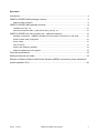
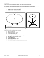
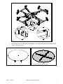
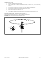
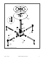
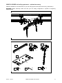
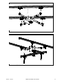
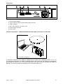
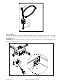
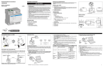
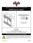
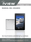
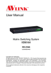
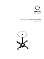
Indexing head ORBITVU SPIDER
User's manual
209.94 - 11/2010
ORBITVU SPIDER User's Manual
2
Spis treści
Introduction...................................................................................................................................4
ORBITVU SPIDER MAXI package contents...............................................................................4
ORBITVU MAXI assembly...........................................................................................................................5
ORBITVU SPIDER MIDI package contents.................................................................................9
Installation (see Fig. 12).............................................................................................................................10
Attaching transparent table – optional accessory (see Fig. 11)................................................................10
ORBITVU SPIDER rail ceiling system set – optional accessory...............................................12
Standard configuration – ORBITVU SPIDER and camera both connected to PC with USB...................15
Shutter release cable configuration ..........................................................................................................16
Power supply..............................................................................................................................................16
Fuse exchange...........................................................................................................................................17
Working with ORBITVU SPIDER...............................................................................................................18
ORBITVU SPIDER firmware upgrade.......................................................................................................18
Technical specifications..............................................................................................................19
Safety precautions and notes....................................................................................................19
Disposal of Waste of Electric and Electric Equipent (WEEE) and meaning of the wheeled bin
symbol (applied in EU)...............................................................................................................20
209.94 - 11/2010
ORBITVU SPIDER User's Manual
3
Introduction
Thank you for purchasing ORBITVU SPIDER – heavy duty universal indexing head.
ORBITVU SPIDER was designed for 360° product photography for loads up to 250 kg. It is controlled with
PC or MAC with ORBITVU EDITOR software. Please, read the manual before you start using it.
ORBITVU SPIDER is available in two basic configurations:
•
ORBITVU MAXI – platform up to 250 kg
•
ORBITVU MIDI – turntable up to 40 kg
Fig. 2: ORBITVU MIDI
Fig. 1: ORBITVU MAXI
ORBITVU SPIDER MAXI package contents
1.
2.
3.
4.
5.
6.
7.
8.
9.
10.
11.
12.
Wing knob M8 – 8 pcs
Platform distance pins – 4 pcs
T-shaped leg wheels – 8 pcs
T-shaped leg feets – 8 pcs
Power supply cable with safety switch, 5 m – 1 pcs
USB cable for ORBITVU SPIDER, 5m – 1 pcs
USB cable for your camera, 5m – 1 pcs
T-shaped llegs - 4 pcs
Platform telescopic arms - 4 pcs
ORBITVU SPIDER base – 1 pcs
180 cm platform – 1 pcs
DVD containing ORBITVU EDITOR software and manuals
209.94 - 11/2010
ORBITVU SPIDER User's Manual
4
1x
8
9
4x
4x
10
1
2
1x
4x
8x
3
4
8x
8x
11
5
7
6
1x
1x
1x
Fig. 3: ORBITVU SPIDER MAXI package contents
ORBITVU MAXI assembly
1, For each T-shaped leg (Fig. 3-8), screw-in 2 feet (Fig. 3-4) and 2 wheels (Fig. 3-3)
4x
Fig. 4: T-shaped legs assembly
209.94 - 11/2010
ORBITVU SPIDER User's Manual
5
2. Insert T-shaped lags to ORBITVU SPIDER base tubes, as shown in Fig. 5. Lock with wing knobs.
A
B
!!! M a x . 2 x
1
A
B
Fig. 5: Fixing T-shaped legs to ORBITVU SPIDER base
3.
Insert platform telescopic arms into top ORBITVU SPIDER base tubes as shown in Fig. 6 . Lock
with wing knobs (Fig. 6-1). Fix 4 platform distance pins (Fig. 6-2).
4.
Level ORBITVU SPIDER using bubble levellers and screwing/unscrewing feet (Fig. 6.- 3).
5.
Connect USB cable into connector found on ORBITVU SPRIDER front panel ( Fig. 19 - 3, 6). If
you plan to use ORBITVU SPRIDER to release shutter in your camera, connect shutter releas
cable now (Fig. 19 - 2)
209.94 - 11/2010
ORBITVU SPIDER User's Manual
6
D
G
3
G
1
2
D
C
Fig. 6: Installation of platform telescopic arms
6.
Place platform on top of the ORBITVU SPRIDER – use positioning bars to properly align it in the
centre – see Fig. 7 i Fig. 8
Fig. 7: ORBITVU SPIDER MAXI top view
Fig. 8: Positioning bars on platform bottom
209.94 - 11/2010
ORBITVU SPIDER User's Manual
7
After proper assembly between each wheel and platform, there should be a gap of 4-5 mm..
!!! 4
7.
F
F
Fig. 9: Widok z boku - dystans pomiędzy platformą a kółkiem
209.94 - 11/2010
ORBITVU SPIDER User's Manual
8
ORBITVU SPIDER MIDI package contents
1
4x
2
3x
3
4
4x
3x
6
7
1x
1x
5
8
1x
1x
9
11
10
1x
1x
2x
12
4x
14
13
1x
15
1x
1x
Fig. 10: Zawartość opakowania ORBITVU SPIDER MAXI
1.
2.
3.
4.
5.
6.
7.
8.
9.
10.
11.
12.
13.
14.
15.
16.
Wing knob M8 – 4 pcs
Column screw M8x12 – 3 pcs
Table screw M5x10 – 3 pcs
Feet – 4 pcs
Power supply cable with safety switch, 5 m – 1 pcs
M5 allen key – 1 pcs
M8 allen key – 1 pcs
Column – 1 pcs
USB cable for ORBITVU SPIDER, 5m – 1 pcs
USB cable for your camera, 5m – 1 pcs
16mm adapter – 2 pcs
I-shaped legs – 4 pcs
ORBITVU SPIDER base – 1 pcs
75 cm aluminium table – 1 pcs
White background with markers – 1 pcs
DVD containing ORBITVU EDITOR software and manuals
209.94 - 11/2010
ORBITVU SPIDER User's Manual
9
Installation (see Fig. 12)
1.
For each I-shaped leg (12) attach foot (4)
2.
Insert I-shaped lags to ORBITVU SPIDER base tubes, as shown in Fig. 12. Lock with wing
knobs (1).
3.
Use screws (2) and allen key (7) to attach column (8) to ORBITVU SPIDER base
4.
Use screws (3) and allen key (6) to attach table (8) to the column
5.
Put the white background on table top (15)
6.
Level ORBITVU SPIDER using bubble levellers and screwing/unscrewing feet (Fig. 6.- 3).
Attaching transparent table – optional accessory (see Fig. 11)
Attach the table as described above in p. 3. but use supplied screws M5x16.
WARNING! Max. load for transparent table is limited to 10 kg
M
3 x M 5 x 16
M
Fig. 11: Attaching transparent table to the column
209.94 - 11/2010
ORBITVU SPIDER User's Manual
10
6
3
I
14
8
I
7
2
11
12
1
4
Fig. 12: ORBITVU SPIDER MIDI assembly
209.94 - 11/2010
ORBITVU SPIDER User's Manual
11
ORBITVU SPIDER rail ceiling system set – optional accessory
ORBITVU SPIDER can be assembled on your rail ceiling system with optional accessory (code 209A1)
WARNING! Before assembly make sure that your rail ceiling configuration is capable of supporting
additional load.
Fig. 13: ORBITVU SPIDER hanging on rail ceiilng system
3
2
1
1x
1x
1x
4
1x
5
4x
6
1x
7
4x
Fig. 14: Package contents
209.94 - 11/2010
ORBITVU SPIDER User's Manual
12
Fig. 15: Assembly 16 mm adaptors
J
L
J
K
L
K
Fig. 16: Hanging support installation
209.94 - 11/2010
ORBITVU SPIDER User's Manual
13
Fig. 17: Fix ORBITVU SPIDER to rail carriages using 16 mm adaptors
Fig. 18: Attach hanging support
209.94 - 11/2010
ORBITVU SPIDER User's Manual
14
Connections
1
2
1
2
3
4
5
3
4
5
6
6
Fig. 19: Front panel
1. Power supply indicator
2. 2.5 mm sub mini stereo shutter release cable connector
3. USB – B socket
4. RS – 232 connector – for service only
5. Power supply connector
6. Fuse socket
Standard configuration – ORBITVU SPIDER and camera both connected to PC with USB
USB
USB
Fig. 20: Standard configuration
In standard configuration both ORBITVU SPIDER and the camera are connected to MAC or PC. It is
recommended configuration, as ORBITVU EDITOR software will control both and images are automatically
downloaded from camera to PC. To use this configuration, your camera must be compatible with ORBITVU
EDITOR. You can find updated compatibility chart on http://www.orbitvu.com
209.94 - 11/2010
ORBITVU SPIDER User's Manual
15
Shutter release cable configuration
USB
Shutter release
Fig. 21: Shutter release cable configuration
In shutter release cable configuration ORBITVU SPIDER is connected to MAC or PC with USB, while the
camera is connected directly ORBITVU SPIDER with shutter release cable. ORBITVU EDITOR software
will control ORBITVU SPIDER, but shutter will be released by ORBITVU SPIDER. No images are
automatically downloaded to PC. Use this configuration, if your camera is not compatible with ORBITVU
EDITOR. You can find updated compatibility chart on http://www.orbitvu.com
Power supply
WARNING! Before connecting power supply, makes sure that voltage in your socket is compatible with
ORBITVU SPIDER power supply specifications. You can find details in this manual, or on the label on the
side of the ORBITVU SPIDER base.
For your safety ORBITVU SPIDER is supplied with special power supply cable equipped with safety switch
(Fig. 22 - 2) and power on switch (Fig. 22 - 3). To switch the unit on/off use no. 3 switch. When ORBITVU
SPIDER is powered, its power indicator will lit continuously (Fig. 19 - 1).
In case of emergency you can quickly switch of the unit pressing switch no. 2. To reset the switch, rotate it in
clockwise direction.
Switch ORBITVU SPIDER off, if you do not use it. Even if not working, it is consuming significant amount of
power for breaking the motor.
WARNING! For safety reasons, always keep the safety switch in visible and easily accessible position. Do
not use other power supply cables to power ORBITVU SPIDER.
209.94 - 11/2010
ORBITVU SPIDER User's Manual
16
4
3
2
1
Fig. 22: Power supply cable with safety switch
Fuse exchange
You can find the fuse inside power supply connector socket. To open the socket, slide it out using
screwdriver or similar tool. Inside the socket you should find two fuses: working one ( Fig. 23 - 1) and spare
one (Fig. 23 - 2).
WARNING! Always exchange the fuse for a fuse with the same parameters – you can find details on the
label on the side of the base.
H
Szc zegó³ H
1
2
H
Fig. 23: Fuse exchange
209.94 - 11/2010
ORBITVU SPIDER User's Manual
17
Working with ORBITVU SPIDER
You control ORBITVU SPIDER using ORBITVU EDITOR software – supplied on separate DVD. You can
find more details inside EDITOR manual.
ORBITVU SPIDER firmware upgrade
You can upgrade ORBITVU SPIDER firmware (software inside the SPIDER) with ORBITVU EDITOR. You
can find more details inside EDITOR manual.
209.94 - 11/2010
ORBITVU SPIDER User's Manual
18
Technical specifications
Max central load ORBITVU MAXI ...............................................................250 kg
Max central load ORBITVU MIDI ..................................................................40 kg
Max central load ORBITVU MIDI with transparent table...............................10 kg
Max. load for hanging configuraton................................................................20 kg
Total weight ORBITVU MAXI.........................................................................61 kg
Total weight ORBITVU MIDI...........................................................................25 kg
Total weight hanging konfiguration.................................................................22 kg
Dimensions ORBITVU MAXI........................................................180×180x22 cm
Dimensions ORBITVU MIDI..........................................................140x140x90 cm
Power supply........................................................................100-230VAC 50/60Hz
Power consumption (max)...............................................................................75W
Power consumption (typical)...........................................................................40W
Power consumption (standby).........................................................................18W
Fuse specification..........................................................................................T1.2A
Position accuracy.......................................................................... better than 0.1º
Operation temperature range....................................................................10-40ºC
Max. operational humidity (rel. non condensing)............................................95%
Acousic noise (max.)......................................................................................60dB
Nominal torque.............................................................................................12 Nm
Connectors:
Power supply ......................................................................IEC 250VAC max
Camera shutter release............................................................2.5 mm stereo
PC Control.....................................................................................USB typu B
Service connector................................................................................RS-232
Safety precautions and notes
•
Make sure safety switch is always in visible and easily accessible place
•
Do not try to use the unit, until it is completely assembled
•
Do not use the unit for any other purpose than 360º photography
•
Keep away from liquids
•
Do not exceed maximal load specification
•
Do not try to use the unit when it is broken
• ORBITVU SPIDER does not require special maintenance , but keep it clean and it will serve you for
long time
209.94 - 11/2010
ORBITVU SPIDER User's Manual
19
Disposal of Waste of Electric and Electric Equipent (WEEE) and meaning of the wheeled
bin symbol (applied in EU)
In 2002, the European Union introduced the Directive on Waste Electrical and Electronic
Equipment (WEEE). The main aim of the Directive is to ensure that WEEE is collected
and treated separately. WEEE is a vast source of raw materials- letting this potential
source of such materials go to waste is unacceptable. If equipment is collected
separately, it can be recycled and up to 85 to 90% of the equipment can be reused as
new material, saving the use of virgin raw materials and energy of producing these.
For the above reasons, VENTIS expects end-users to dispose of the material in an
environmentally friendly way, being separate collection and treatment.
Electrical and Electronic Equipment is labeled with the following “crossed out wheeled
bin” symbol indicating that the equipment should be disposed of, by the end-user,
separate from other types of waste. End-users should contact their dealer/distributor or our company on
disposal, collection and recycling options in their country.
209.94 - 11/2010
ORBITVU SPIDER User's Manual
20
209.94 - 11/2010
ORBITVU SPIDER User's Manual
21