1
US008313039B2
(12) Umted States Patent
(10) Patent N0.:
Flick et al.
(54)
(75)
(45) Date of Patent:
REMOTE CLIMATE CONTROL SYSTEM
6,346,876 B1
*Nov. 20, 2012
2/2002 Flick ........................... .. 340/426
PROVIDING AN INDICATION RELATING TO
g?
?llet
REMOTE CLIMATE CONTROL OPERATION
6,756,886 B2
6/2004 Flick
AND ASSOCIATED METHODS
6,812,829 B1
6,828,901 B2
,
Inventors: Kenneth E. Flick, Douglasville, GA
(US)' Michael Stephen Thompson
’
-
’
Douglasvlne’ GA (Us)
_
_
(73) Asslgneez Omega Patents, L.L.C., Douglasvllle,
GA (Us)
(*)
US 8,313,039 B2
Notice:
,
1c
11/2004
12/2004
Flick ............ ..
Birch?eld et a1.
~~~3jo?ggl62f
.
340M261
.. 340/42613
....... .. 340/10
7,010,402 B2
3/2006 Flick
701/36
7,031,826 B2
4/2006 Flick
..... .. 701/113
7,046,126 B2
5/2006
7,068,153 B2
6/2006 Flick ..... ..
Flick
7,091,822 B2
8/2006
.. 340/42636
.. 340/42636
Flick et al. ................. .. 340/5.72
_
(Continued)
Subject to any disclaimer, the term of this
OTHER PUBLICATIONS
Pawnt 15 extended or adlusted under 35
Excalibur 1800 ATV Gold Series Owners Manual, Omega Research
U'S'C' 15403) by 641 days‘
& Development Inc., 1998, pp. 3-50.
This patent is subject to a terminal dis-
(Continued)
clalmer.
(21) APPI' NO‘: 12/571,050
Primary Examiner * Chen Wen JIang
(22) Filed;
Milbrath & Gilchrist, PA.
(74) Attorney, Agent, or Firm * Allen, Dyer, Doppelt,
sep_ 30, 2009
(65)
Prior Publication Data
Us 2011/0073667 A1
(57)
Man 31’ 2011
(51) Int. Cl.
starting an electrically poWered climate control system based
G05D 23/00
B60H 1/32
360G 17/018
(52)
(58)
ABSTRACT
A remote climate control system for a vehicle includes a
remote climate controller to be positioned at a vehicle for
(2006.01)
(2006.01)
(200601)
upon a remote climate control handheld unit and causing the
electrically powered climate control system to run for a run
time period before shutting it off. The remote climate con
US. Cl. ............................. .. 236/51; 62/244; 701/36
Field of Classi?cation Search .................. .. 62/ 126,
troller is resettable based upon the remote climate control
handheld unit to cause the electrically powered climate con
62/244; 236/51; 165/42; 701/36; 123/1792,
123/1793
See application ?le for complete Search history,
trol system to run for an additional run time period before
shutting it off. The remote climate control handheld unit has
an indicator for providing an indication to a user prior to
expiration of the run time period to permit a user to reset the
(56)
References Cited
run time period While the electrically poWered climate control
system is still running and before shutting off the electrically
poWered climate control system.
U.S. PATENT DOCUMENTS
5,719,551 A
6,011,460 A
2/1998
1/2000
Flick ........................... .. 340/426
Flick ........................... .. 340/426
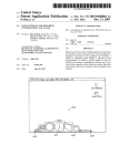
25 Claims, 12 Drawing Sheets
28‘ “N
OATA COMMUNICATIONS BOS
REMOTE START
CONTROLLER
4s\
,,
TAEl'lLElNDlCATOR
\ ggglillllmmrlulllmi
BUS INTERFACE
AUDIBLEINDICATON
'illéi‘il‘éiilllli'i‘li‘ll‘i“
minim»
SEEUKFIY
CIRCUIT
US 8,313,039 B2
Page 2
U.S. PATENT DOCUMENTS
7,205,679
7,224,083
7,280,908
7,369,936
7,378,945
2006/0080007
2006/0087405
4/2007 Flick .......................... .. 307/10.3
5/2007 Flick .......................... .. 307/106
10/2007 Maehara et al.
5/2008 Flick ........................... .. 701/113
5/2008 Flick ......... ..
. 340/4261
4/2006 Gerard et al. ................... .. 701/2
4/2006 Koike et a1.
2008/0203815 A1
8/2008 OZaWaetal.
2011/0073059 A1*
3/2011
Flick ........................ .. 123/179.2
OTHER PUBLICATIONS
Excalibur AL-2000-EDP, Operation Manual, Omega Research &
Development Inc., Mar. 2007, pp. 1-43.
* cited by examiner
US. Patent
Nov. 20, 2012
Sheet 1 0f 12
US 8,313,039 B2
US. Patent
Nov. 20, 2012
Sheet 2 0f 12
US 8,313,039 B2
2%
mama
g1
US. Patent
Nov. 20, 2012
2
m
Sheet 3 0f 12
US 8,313,039 B2
US. Patent
Nov. 20, 2012
Sheet 4 0f 12
US 8,313,039 B2
I;zmm
I
EggENm/)W,N/
gmm?ag?a
M
f//aEW?xmaEw“?g%mm3mm?
aE?xmiw?fiw//amfi“mEgma? :.i!
J/Mam“?
m-.1 :
.i Emwi /.I lEi w. i
gm.
ILHW
3 mm
U
/hi=m
fix5%
@
US. Patent
“W
Nov. 20, 2012
Sheet 5 0f 12
US 8,313,039 B2
SENS AN ALERT H) THE REEEQTE m1 HAKQHELB mm HER
"m EXFERAHSEKE Q? WE m TEME ¥ERIG3
%
55 xxx/K
FERE?ESi?FEAiFRGMEMYE
mm am am TIME
__
------------------------------------------------------------
mmmmasumw
;
57’\
SHLEWFHHE mm
~
US. Patent
Nov. 20, 2012
Sheet 6 0f 12
US 8,313,039 B2
53
m A mm mama am
A as
m
€ASE TE mm m
'EEME FEREQE
m:
m A
5552145 52H m m
H ma
mi‘mam.
iiAéE?HEL
FR
@EME PERU}
55M
HSE TE
,
m1?
ES SW1 RQNIEG
s?mwia mm
-
US. Patent
Nov. 20, 2012
Sheet 7 0f 12
US 8,313,039 B2
US. Patent
Nov. 20, 2012
Sheet 8 0f 12
US 8,313,039 B2
m?WEEHm@uwmgan.
n
US. Patent
win1%as.
A,
w,
NOV. 20, 2012
a
a“
"i"
T
“‘523%gN% ?gma s
Sheet 9 0f 12
US 8,313,039 B2
"T
1/m;E3mam.\\a$5Ema?
l.
ix 3‘,.
US. Patent
Nov. 20, 2012
Sheet 10 0f 12
US 8,313,039 B2
3%T
/
ml a iI!
mam
il / ,
US. Patent
Nov. 20, 2012
Sheet 11 0112
%
%
155 “N
NM”J\\
»
mm 111111111 115
1
mm 11am
1111mm
1% a
US 8,313,039 B2
US. Patent
Nov. 20, 2012
3TH" é RFEEEQE’S REGRE
SEAR? MERE
353
Sheet 12 0f 12
US 8,313,039 B2
FGWEE
{NYE 3¥§TE ASEE F?? A
QASE I? T GK F92 A Rim TEE §ERIGB
i
_\
== PRQVIBE
PERi?,
TEAN
"i3 AME
ER
PERM?
3%THE
§EREG§
Ii‘iDIiAYE
§ER3E’m353E525
ESE
TE @5558
‘i'iiE éEMTE
& PREER
ESE? $1M“
m EXPIHQK
TEE
HMEELB
FH 0Fmay
$5M.
“EHE TRUN
US 8,313,039 B2
1
2
REMOTE CLIMATE CONTROL SYSTEM
PROVIDING AN INDICATION RELATING TO
REMOTE CLIMATE CONTROL OPERATION
AND ASSOCIATED METHODS
mate control system to run for a run time period before shut
ting off the electrically poWered climate control system.
The remote climate controller may also be resettable based
upon the remote climate control handheld unit to cause the
electrically poWered climate control system to run for an
additional run time period While the electrically poWered
climate control system is still running and before shutting off
the electrically poWered climate control system. The remote
FIELD OF THE INVENTION
The present invention relates to the ?eld of remote vehicle
control, and, more particularly, to a remote vehicle control
system such as to start an engine and related methods.
climate control handheld unit may also include an indicator
cooperating With the processor for providing an indication to
a user prior to expiration of the run time period. This permits
a user to use the remote climate control handheld unit to reset
BACKGROUND OF THE INVENTION
The passenger compartment of a vehicle parked outside
during a cold day may become very cold, With temperatures
reaching that of the ambient air outside the vehicle. Likewise,
the passenger compartment of a vehicle parked outside during
a hot day may become very hot, very quickly, With tempera
tures that greatly exceed that of the ambient air outside the
vehicle.
Some drivers start a vehicle, activate the vehicle’s climate
control system, then leave the vehicle until the climate control
system begins to heat or cool the vehicle. HoWever, this
requires the driver to leave the comfort of the indoors,
the run time period While the electrically poWered climate
control system is still running and before shutting off the
electrically poWered climate control system.
This remote starting system provides additional conve
nience and addresses various draWbacks of the prior art. Hav
ing to restart the engine When the user desires the engine to
20
run for another run time period, as per the prior art, may not be
desirable for a variety of reasons. A signi?cant percentage of
engine Wear occurs at startup, and this remote starting system
helps reduce engine Wear due to unnecessary starting and
25
restarting. Moreover, the remote starting system may help to
reduce the amount of pollutants produced by the engine since
it Will not be started, stopped, then restarted unnecessarily.
momentarily enter the vehicle, start the engine and operate
During this starting, stopping, and restarting of the engine
the climate control system, and leave the vehicle unattended
as per the prior art, a vehicle’s climate control system may
With the engine running.
immediately cease to function When the engine is shut off,
thereby alloWing the passenger compartment of the vehicle to
To avoid this, remote starting systems have been developed
Which alloW a driver to start a vehicle’ s engine Without enter
30
back as Well.
The vehicle may further comprise a sensor associated With
the electrical poWer source and the remote climate controller
include a remote start controller positioned at a vehicle that
causes an engine starter to start an engine based upon a remote
start handheld unit, such as a key fob.
More advanced remote starting systems, such as the
35
comprise a tactile indicator and the indication may comprise
a tactile indication. Additionally or alternatively, the indicator
may comprise an audible indicator and the indication may
40
tems are alleviated.
Systems such as the Excalibur AL-2000-EDP provide the
may also be for starting the electrically poWered climate
control system based upon the sensor. The indicator may also
Excalibur AL-2000-EDP, produced and sold by Omega
Research & Development (Douglasville, Ga.) have been
developed. The user’s manual to this system explains that its
remote start controller, after having remotely started a vehi
cle’s engine, shuts the engine off after a run time period. By
limiting the duration the engine may run When remotely
started, the draWbacks of less advanced remote starting sys
heat up or cool doWn contrary to the user’ s desire. The remote
starting system of the present invention addresses this draW
ing the vehicle. Typical remote starting systems, such as that
disclosed in US. Pat. No. 6,828,901 to Birch?eld et al.,
45
user With a visual indication of the remaining run time period,
and that the run time period has expired and that the engine is
shut off, thereby alloWing the user to once again remotely
start the engine for another run time period if desired.
50
SUMMARY OF THE INVENTION
comprise an audible indication. The indicator may also com
prise a visible indicator and the indication may comprise a
visible indication.
The processor may implement a timing function to operate
the indicator. Additionally or alternatively, the remote climate
controller may implement a timing function to send an alert to
the remote climate control handheld unit prior to expiration of
the run time period and the processor of the remote climate
control handheld unit may provide the indication based upon
the alert. In addition, the remote climate controller may have
a settable run time period.
The vehicle may have a data communications bus extend
ing throughout the vehicle and the remote climate controller
In vieW of the foregoing background, it is therefore an
object of the present invention to provide a remote climate
control system for a vehicle With greater convenience.
This and other objects, features, and advantages in accor
dance With the present invention are provided by a remote
climate control system for a vehicle comprising an electrical
poWer source and an electrically poWered climate control
system selectively poWered thereby that provides an indica
may cause a climate control start signal to be generated on the
data communications bus for starting the electrically poWered
55
cally poWered climate control system.
60
tion for a user before the engine has been shut off. The remote
climate control system may comprise a remote climate con
trol handheld unit comprising a housing and a processor
carried thereby. A remote climate controller may be posi
tioned at the vehicle for starting the electrically poWered
climate control system based upon the remote climate control
handheld unit to cause causing the electrically poWered cli
climate control system. Additionally, the remote climate con
troller may cause a climate control stop signal to be generated
on the data communications bus for shutting off the electri
The electrically poWered system may comprise at least one
of an electrically poWered air conditioning (AC) compressor,
an electrical heater, and an electrical ventilation bloWer. The
remote climate control handheld unit may comprise a cellular
telephone. The remote climate controller may be a multi
vehicle compatible remote climate controller.
65
A method aspect is directed to a method of using a remote
climate control system for a vehicle comprising an electrical
poWer source and an electrically poWered climate control
US 8,313,039 B2
3
4
system selectively powered thereby. The method may include
starting the electrically powered climate control system, with
out, and prime and multiple prime notation are used to indi
cate similar elements in alternative embodiments.
a remote climate controller positioned at the vehicle, based
upon a remote climate control handheld unit and the electri
an engine 29 of a vehicle 21 is now described. The engine 29
Referring initially to FIG. 1, a remote starting system 20 for
may be an internal combustion engine that burns gasoline,
diesel, ethanol, or other fuels, for example. The vehicle 21
also includes an engine starter 28 for starting the engine 29. In
addition, the vehicle 21 includes a security circuit 30 con
nected to the engine starter 28 to selectively disable the opera
tion thereof and therefore the operation of the engine 29.
Indeed, in some applications, the security circuit 30 may
selectively disable operation of a plurality of, or all of, the
devices and functions of the vehicle 21.
cally powered climate control system, and causing the elec
trically powered climate control system to run for a run time
period before shutting off the electrically powered climate
control system. The method may further include generating
an indication, using an indicator, to a user prior to expiration
of the run time period to permit a user to use the remote
climate control handheld unit to reset the run time period to
cause the electrically powered climate control system to run
for an additional run time period, while the electrically pow
The vehicle 21 has a data communications bus 27 extend
ered climate control system is still running and before shut
ing throughout. The data communications bus 27 may extend
ting off the electrically powered climate control system.
through the engine compartment, the passenger compart
BRIEF DESCRIPTION OF THE DRAWINGS
FIG. 1 is a schematic block diagram of a remote starting
system for an engine of a vehicle in accordance with the
20
and/or the engine starter 28 need not be on the data commu
present invention.
FIG. 2 is a schematic block diagram of a further embodi
ment of a remote starting system for an engine of a vehicle in
accordance with the present invention.
FIG. 3 is a schematic block diagram of yet another embodi
25
ment of a remote starting system for an engine of a vehicle in
accordance with the present invention.
FIG. 4 is a schematic block diagram of still another
embodiment of a remote starting system for an engine of a
30
vehicle in accordance with the present invention.
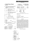
FIG. 5 is a ?owchart of a method of operating a remote
starting system in accordance with the present invention.
FIG. 6 is a ?owchart of another method of operating a
remote starting system in accordance with the present inven
tion.
35
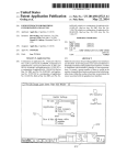
FIG. 7 is a schematic block diagram of a remote climate
control system for a vehicle in accordance with the present
invention.
FIG. 8 is a schematic block diagram of a further embodi
nications bus 27. Indeed, one of, or both of the security circuit
30 and the engine starter 29 may be on the data communica
tions bus 27. Furthermore, each of the security circuit 30 and
the engine starter 29 may communicate unidirectionally via
the data communications bus 27, or may communicate bidi
rectionally via the data bus. Each of the security circuit 30 and
the engine starter 29 need not communicate in the same
manner via the data communications bus 27. For example, the
security circuit 30 may communicate bidirectionally while
the engine starter 28 communicates unidirectionally.
It should be understood that there may be intervening cir
cuitry, such as a body control module, engine control module,
or powertrain control module, for example, between the data
communications bus 27, the security circuit 30, and/or the
engine starter 29.
The remote starting system 20 illustratively includes a
remote start handheld unit 40 comprising a housing 29. The
housing carries a processor 41 coupled to a transceiver 43, a
40
ment of a remote climate control system for a vehicle in
memory 44, a vibration unit 45, a speaker 46, a display 47,
and an input device 48. Further details of the functions of
these components will be given below.
accordance with the present invention.
FIG. 9 is a schematic block diagram of yet another embodi
ment of a remote climate control system for a vehicle in
accordance with the present invention.
ment, and/ or the trunk of the vehicle 27. The security circuit
30 and the engine starter 28 are each coupled to the data
communications bus 27 for communication thereover. Those
of skill in the art will understand that the security circuit 30
45
The remote starting system 20 also includes a transceiver
26 to be positioned at the vehicle 21. In addition, the remote
starting system 20 includes a remote start controller 22 to be
FIG. 10 is a schematic block diagram of a further embodi
ment of a remote climate control system for a vehicle in
positioned at the vehicle 21 for starting the engine 29 based
upon the remote start handheld unit 40, thereby causing the
accordance with the present invention.
engine to run for a run time period before shutting off the
engine 29. To start the engine 29, the remote start controller
FIG. 11 is a ?owchart of a method of operating a remote
climate control system in accordance with the present inven
tion.
FIG. 12 is a ?owchart of another method of operating a
remote climate control system in accordance with the present
invention.
50
communications bus 27 for operating the engine starter 28,
55
DETAILED DESCRIPTION OF THE PREFERRED
EMBODIMENTS
which then starts the engine. It should be understood that the
remote start controller 22 itself may not generate the engine
start signal on the data communications bus 27, but instead
may cause an intervening component to generate the engine
start signal on the data communications bus. Of course, in
some applications, the remote start controller 22 may instead
be coupled to the engine starter 28 via the hardwire interface
24, and may operate the engine starter to start the engine 29
via the hardwire interface instead of via the data bus.
The present invention will now be described more fully
hereinafter with reference to the accompanying drawings, in
which preferred embodiments of the invention are shown.
This invention may, however, be embodied in many different
The communications from the remote start handheld unit
40 to the transceiver 26 at the vehicle 21 is typically a direct
radio frequency link. In other words, there are no intervening
forms and should not be construed as limited to the embodi
ments set forth herein. Rather, these embodiments are pro
vided so that this disclosure will be thorough and complete,
and will fully convey the scope of the invention to those
skilled in the art. Like numbers refer to like elements through
40 causes an engine start signal to be generated on the data
communications links. However, in other embodiments, the
65
remote start handheld unit 40 may indirectly communicate
with the transceiver 26 via other communications infrastruc
ture, such a satellite, the public switched telephone network
US 8,313,039 B2
5
6
(PSTN), and/ or over the World Wide Web or Internet, as Will
tions may be settable based upon input received via the input
be appreciated by those skilled in the art.
device 48. Of course, the speech message or pattern of tones
The remote start handheld unit 40 may be a common
may also be settable based upon input receives via the input
remote transmitter. By common remote transmitter, it is
device 48.
With reference to FIG. 2, an alternative embodiment of the
meant that the remote start handheld unit 40 may operate a
plurality of vehicles 21. Such a feature may be desirable to a
remote start controller 22' is noW described. In this embodi
ment, the remote start handheld unit 40' comprises a cellular
driver Who oWns multiple vehicles 21 or to a rental car com
pany, for example.
telephone. In addition, the run time period is settable, for
example based upon the cellular telephone 40'. The run time
period may also be settable based upon a sWitch (not shoWn)
The remote start controller 22 may be a multi-vehicle com
patible remote start controller that cooperates With the trans
ceiver 26. Those of skill in the art Will understand that the
transceiver 26 and the remote start controller 22 may be
associated together in a same housing. In fact the transceiver
26 and the remote start controller 22 may each be embodied
connected to the remote start controller 22', or based upon a
signal received over the data communications bus 27' from
another component.
In addition, in this embodiment, the remote start controller
on a same printed circuit board or even in a same integrated
22' is multi-vehicle compatible. By multi-vehicle compatible,
circuit. The remote start controller 22 illustratively bypasses
the security circuit 30 to enable operation of the engine starter
28 to thereby start the engine 29.
it is meant that the remote start controller 22' may be able to
communicate With other devices on the data bus 27' using a
desired set of codes from among a plurality of different sets of
The remote start controller 22 is coupled to the data com
munications bus 27 extending Within the vehicle 21, via the
20
bus interface 25, for communication thereover With the secu
rity circuit 30 and engine starter 28. Those skilled in the art
Will appreciate that there may be intervening components
betWeen the bus interface 25 and the data communications
bus 27, such as a body control module, engine control mod
ule, or poWertrain control module. Of course, in some
embodiments, the remote start controller 22 may communi
cate With the security circuit 30 and/or engine starter 28 via a
hardWired connection at the hardWire interface 24. In some
embodiments, the vehicle 21 may not have a data bus 27.
The run time period is resettable based upon the remote
start handheld unit 40 to cause the engine 29 to run for an
additional run time period, or other time period, While the
25
In some embodiments, the remote start controller 22'
30
in the form of a cellular telephone prior to expiration of the
35
run time period. The processor 41' of the cellular telephone
provides the tactile or audible indication based upon the alert.
In this embodiment, the tactile indication is a pattern of vibra
tions, and the audible indication is a speech message or pat
tern of tones. In some embodiments, the remote start hand
40
If the run time period expires before being reset, the remote
start controller 22 stops the engine. To stop the engine, the
remote start controller 22 may cause an engine stop signal to
be generated on the data communications bus 27. It should be
understood that the remote start controller 22 itself may not
implements a timing function executed by a timer 31' of the
processor 23' to send an alert to the remote handheld unit 22'
period. This advantageously alloWs a user to keep the engine
29 running for a greater period of time than the run time
period Without the engine being stopped.
multi-vehicle compatible devices and operation may be found
in the folloWing references, each of Which is incorporated by
reference herein in its entirety, and assigned to the assignee of
the present invention. U.S. Pat. Nos. 7,378,945; 7,369,936;
7,224,083; 7,205,679; 7,091,822; 7,068,153; 7,046,126;
7,031,826; 7,010,402; 6,812,829; 6,756,886; 6,756,885;
6,529,124; 6,346,876; 6,011,460; and 5,719,551.
engine is still running and before shutting off the engine. That
is, the transceiver 43 of the remote start handheld unit 40 may
be operated by a user to transmit a signal to the remote start
controller 22 instructing it to reset or extend the run time
codes for different vehicles or vehicle platforms.
In other Words, the same remote start controller 22' may be
installed in a variety of different vehicles. More details of
held unit 40' may include a microphone (not shoWn) for
recording the speech message, and a plurality of songs and/or
speech messages may be stored in the memory 44', each to be
used as a pattern of tones.
45
Other components of the remote starting system 20' are
similar to those described above With reference to FIG. 1.
Those components therefore need no further discussion
herein.
generate the engine stop signal on the data communications
In some embodiments, the remote starting system 20"
bus 27, but instead may cause an intervening component to
(FIG. 3) may provide only a tactile indication through the
generate the engine stop signal on the data communications
bus. Of course, in hardWired embodiments, the engine may
also be shut doWn.
vibration unit 45", and may not have a speaker. In other
The vibration unit 45 of the remote start handheld unit 40
cooperates With the processor 41 for providing a tactile indi
cation to a user prior to expiration of the run time period.
Additionally or alternatively, the speaker 46 may provide an
audible indication to the user prior to the expiration of the run
50
embodiments, the remote starting system 20'" (FIG. 4), many
only provide an audible indication through the speaker 46"',
and may not have a vibration unit. Other components of the
remote starting systems 20", 20'" are similar to those
described above With reference to FIG. 2. Those components
55
therefore need no further discussion herein.
With reference to the ?owchart 50 of FIG. 5, a method of
operating a remote starting system in a vehicle is described.
time period. This permits the user to use the remote start
handheld unit 40 to reset the run time period While the engine
After the start (Block 51), at Block 52, the vehicle’s engine is
is still running and before shutting off the engine, for example
by entering a command into the input device 48.
run for a run time period.
The display 47 of the remote start handheld unit 40 may
cooperate With the processor 41 for providing a visual indi
cation to the user prior to expiration of the run time period.
The visual indication may be a countdoWn until the expiration
of the rune time period, for example.
The processor 41 of the remote start handheld unit 39
includes a timer 49 executing a timing function to operate the
vibration unit 45, and/ or the speaker 46. The pattern of vibra
started based upon a remote start handheld unit and caused to
60
At Block 53, an alert is sent to the remote start handheld
unit prior to expiration of the run time period. At Block 54, a
tactile indication is provided to a user to permit the user to use
65
the remote start handheld unit to reset the run time period by
sending a reset run time period signal.
If a reset run time period signal is not received at Block 55,
the engine is shut off at Block 57. If a reset run time period
signal is received from the remote start handheld unit at Block
US 8,313,039 B2
7
8
55, the engine is caused to run for an additional run time
poWered AC unit. It may be advantageous to use an electrical
ventilation bloWer to cool the passenger compartment of the
vehicle 121 as opposed to an electrical AC unit because the
electrical ventilation bloWer may consume less electricity
than an electrical AC unit.
A suitable electrical heater may be a resistive heater or
other suitable heater as knoWn to those of skill in the art. In
addition, a suitable electrical heater may be a combination
heater, for example a heater core With electrical heater coils,
Which employs both resistive heating and the use of Waste
period at Block 56. At this point, an alert is again sent to the
remote start handheld unit prior to expiration of the run time
period at Block 53 again. The steps repeat until a reset run
time period signal is not received from the remote start hand
held unit at Block 55. At this point, the engine is shut off at
Block 57. Block 58 indicates the end of the method.
With reference to the ?owchart 60 of FIG. 6, another
method of operating a remote starting system is noW
described. After the start (Block 61), at Block 62, the vehi
cle’ s engine is started based upon a remote start handheld unit
and caused to run for a run time period.
At Block 63, an audible indication is provided to a user,
heat from the engine 129 to heat the passenger compartment
ofthe vehicle 121.
A suitable electrically poWered AC unit may be a conven
prior to expiration of the rune time period, to permit the user
tional AC compressor coupled to an electric motor via a belt
or may be an AC compressor having an internal electric
motor. In some embodiments, the electrical AC unit may be a
thermoelectric cooler or other suitable electric AC unit as
knoWn to those of skill in the art.
to use the remote start handheld unit to reset the run time
period by sending a reset run time period signal.
If a reset run time period signal is not received at Block 64,
the engine is shut off at Block 66. If a reset run time period
signal is received from the remote start handheld unit at Block
64, the engine is caused to run for an additional run time
20
provided to the user at Block 63. The steps repeat until a reset
run time period signal is not received from the remote start
handheld unit at Block 64. At this point, the engine is shut off
at Block 66. Block 67 indicates the end of the method.
25
The vehicle 121 has a rechargeable battery 135, although
30
the rechargeable battery 135. Skilled artisans Will appreciate
compartment, and/ or the trunk of the vehicle 121.
35
The sensor 134 is coupled to the rechargeable battery 135
and reads the voltage thereof. The sensor 134 may, addition
ally or alternatively, be able to detect Whether the recharge
An optional separate engine starter 128 starts the engine 129.
Those of skill in the art Will understand that the engine 129
may instead be started by the electric motor 136.
It should be understood that the engine 129 may be an
vehicle 121.
The vehicle 121 has a data communications bus 127
extending throughout. The data communications bus 127
may extend through the engine compartment, the passenger
that there may be more than one electric motor 136 and more
than one rechargeable battery 135. In some embodiments, the
vehicle 121 is a hybrid vehicle and has an engine 129 that
operates a generator or alternator (not shoWn) to recharge the
rechargeable battery 135 and/or poWer the electric motor 136.
circuit 130 may also be connected to the engine starter 128 to
selectively disable the operation thereof and therefore the
operation of the engine 129. Indeed, in some applications, the
security circuit 130 may selectively disable operation of a
plurality of, or all of, the devices and functions of the hybrid
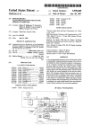
Referring noW to FIG. 7, another embodiment of a remote
climate control system 120 for a vehicle 121 is noW described.
those of skill in the art Will appreciate that the vehicle may
have another rechargeable electrical poWer source. The
vehicle 121 has an electric motor 136 electrically poWered by
The vehicle 121 may also include a security circuit 130
connected to the electrically poWered climate control system
132. The security circuit 130 selectively disables the electri
cally poWered climate control system 132. Those of skill in
the art Will appreciate that, in some applications, the security
period at Block 65.At this point, an audible indication is again
able battery is connected to an external poWer source 137. The
external poWer source 137 may be an electrical socket or
40
recharging station, for example.
The electrically poWered climate control system 132, the
internal combustion engine that burns gasoline, diesel, etha
sensor 134, the security circuit 130, and the engine starter 128
nol, or other fuels. Rather than an internal combustion engine
129, the vehicle 121 may instead have an external heat engine,
such as a Stirling engine.
are each coupled to the data communications bus 127 for
communication thereover. Those of skill in the art Will under
45
The vehicle 121 further comprises an electrically poWered
stand that each of the electrically poWered climate control
system 132, the sensor 134, the security circuit 130, and the
climate control system 132 selectively poWered by the
engine starter 128 need not be on the data communications
rechargeable battery 135 and a sensor 134 associated With the
bus 127. Indeed, one of, or a plurality of electrically poWered
climate control system 132, the sensor 134, the security cir
cuit 130, and the engine starter 128 may be on the data
communications bus 127. Furthermore, each of the electri
rechargeable battery. By electrically poWered climate control
system 135, it is means that the climate control system is not
50
driven by mechanical poWer from the engine 129 and instead
receives electrical poWer from the rechargeable battery 135 or
an alternator/generator (not shoWn) coupled to the engine
cally poWered climate control system 132, the sensor 134, the
security circuit 130, and the engine starter 128 may commu
nicate unidirectionally via the data communications bus 127,
129. Alternatively, the electrically poWered climate control
system 135 may receive mechanical poWer from a motor (not
shoWn) coupled to the rechargeable battery 135 or an alter
55
nator/generator (not shoWn) coupled to the engine 129, but
not from the engine itself.
starter 128 need not communicate in the same manner via the
The electrically poWered climate control system 132 may
include an electrical ventilation bloWer, an electrical heater,
and/or an electrically poWered AC compressor. A suitable
electrical ventilation bloWer may be a conventional bloWer
60
data communications bus 127. For example, the electrically
poWered climate control system 132 may communicate bidi
rectionally While the sensor 134 communicates unidirection
ally.
coupled to an electric motor via a belt or may be a bloWer
having an internal electric motor. It should be understood that
such an electrical ventilation bloWer merely bloWs ambient
outside air into the passenger compartment of the vehicle 121
and does not actively cool the air, as Would an electrically
or may communicate bidirectionally via the data bus. In addi
tion, each of the electrically poWered climate control system
132, the sensor 134, the security circuit 130, and the engine
65
It should be understood that there may be intervening cir
cuitry, such as a body control module, engine control module,
or poWertrain control module, betWeen the electrically poW
ered climate control system 132, the sensor 134, the security
circuit 130, and/or the engine starter 128.
US 8,313,039 B2
10
The remote climate control system 120 includes a remote
The remote climate controller 122 is coupled to the data
start handheld unit 140 comprising a housing 129. The hous
ing carries a processor 141 coupled to a transceiver 143, a
communications bus 127 extending Within the vehicle 121,
via the bus interface 115, for communication thereover With
the security circuit 130 and optional engine starter 128. The
bus interface 115 includes circuitry for interfacing to the
proper signal levels and formats on the data communications
bus 127 as Will be appreciated by those skilled in the art
Without further discussion herein.
Those skilled in the art Will appreciate that there may be
intervening components betWeen the bus interface 125 and
the data communications bus 127, such as a body control
memory 144, a vibration unit 145, a speaker 146, a display
147, and an input device 148. Further details of the functions
of these components Will be given beloW.
The remote climate control system 120 includes a trans
ceiver 126 to be positioned at the vehicle 121. In addition, the
remote climate control system 120 includes a remote climate
controller 122 to be positioned at the vehicle 121 for starting
the electrically poWered climate control system 132 based
module, engine control module, or poWertrain control mod
upon the remote climate control handheld unit 140, thereby
ule. Of course, in some embodiments, the remote climate
causing the electrically poWered climate control system 132
controller 122 may communicate With the security circuit 130
and/or optional engine starter 128 via a hardWired connection
at the hardWire interface 124. In fact, in some embodiments,
to run for a run time period before shutting off the electrically
poWered climate control system 132.
The remote climate control handheld unit 140 may cause
the remote climate controller 122 to heat the passenger com
partment of the vehicle 121 to a pre-set temperature. Alterna
tively, the remote climate control handheld unit 140 may have
20
run time period, or other time period, While the electrically
buttons that enable a user to set the temperature to Which the
remote climate controller 122 is to heat the passenger com
poWered climate control system is still running and before
shutting off the electrically poWered climate control system
partment of the vehicle 121. Additionally or alternatively, the
remote climate control handheld unit 140 may have buttons
(input device 148) that enable a user to select to Which of a
25
plurality ofpre- set temperatures the remote climate controller
122 is to heat the passenger compartment of the vehicle 121.
132. That is, the transceiver 143 of the remote climate control
handheld unit 140 may transmit a signal to the remote climate
controller 122 instructing it to reset or extend the run time
period. This advantageously alloWs a user to keep the electri
cally poWered climate control system 132 running for a
greater period of time than the run time period Without the
To start the electrically poWered climate control system
132, the remote climate controller 140 causes a climate con
trol start signal to be generated on the data communications
the vehicle 121 may not have a data bus 127.
The run time period is resettable based upon the remote
climate control handheld unit 140 to cause the electrically
poWered climate control system 132 to run for an additional
30
electrically poWered climate control system being stopped.
bus 127 for operating the electrically poWered climate control
If the run time period expires before being reset, the remote
system 132. It should be understood that the remote climate
climate controller 122 stops the electrically poWered climate
control system 132. To stop the electrically poWered climate
controller 122 itself may not generate the climate control start
signal on the data communications bus 127, but instead may
cause an intervening component to generate the climate con
trol start signal on the data communications bus.
The communications from the remote climate control
handheld unit 140 to the transceiver 126 at the vehicle 121 are
35
typically a direct radio frequency link. In other Words, there
are no intervening communications links. HoWever, in other
embodiments, the remote climate control handheld unit 140
may indirectly communicate With the transceiver 126 via
other communications infrastructure, such a satellite, the
public sWitched telephone netWork (PSTN), and/ or over the
World Wide Web or Internet, as Will be appreciated by those
40
held unit 140 cooperates With the processor 141 for providing
a tactile indication to a user prior to expiration of the run time
45
include one or more central station transmitters, such as may
be provided by a satellite transmitter, for example. Such a
central station transmitter may also be connected to other
communications infrastructures. The remote climate control
handheld unit 140 may be a common remote transmitter. By
common remote transmitter, it is meant that the remote cli
mate control handheld unit 140 may operate a plurality of
50
vehicles 121. Such a feature may be desirable to a driver Who
oWns multiple vehicles 121 or to a rental car company, for
55
a visual indication to the user prior to expiration of the run
time period. The visual indication may be a countdoWn until
the expiration of the run time period, for example.
The processor 141 of the remote climate control handheld
unit 139 includes a timer 49 executing a timing function to
The remote climate controller 122 may be a multi-vehicle
compatible remote climate controller that cooperates With the
60
embodied on a same printed circuit board or even in a same
integrated circuit. The remote climate controller 122
period While the electrically poWered climate control system
is still running and before shutting off the electrically poW
ered climate control system, for example by entering a com
mand into the input device 148.
The display 147 of the remote climate control handheld
unit 140 may cooperate With the processor 141 for providing
example.
bypasses the security circuit 30 to enable operation of the
electrically poWered climate control system 132.
period. Additionally or alternatively, the speaker 146 may
provide an audible indication to the user prior to the expira
tion of the rune time period. This permits the user to use the
remote climate control handheld unit 140 to reset the run time
skilled in the art.
The remote climate control handheld unit 140 may also
transceiver 126. Those of skill in the art Will understand that
the transceiver 126 and the remote climate controller 122 may
be associated together in a same housing. In fact the trans
ceiver 26 and the remote climate controller 122 may each be
control system 132, the remote climate controller 122 may
cause a climate control stop signal to be generated on the data
communications bus 127. It should be understood that the
remote climate controller 122 itself may not generate the
climate control stop signal on the data communications bus
127, but instead may cause an intervening component to
generate the climate control stop signal on the data commu
nications bus.
The vibration unit 145 of the remote climate control hand
65
operate the vibration unit 145 and the speaker 146. The pat
tern of vibrations may be settable based upon input received
via the input device 148. Of course, the speech message or
pattern of tones may also be settable based upon input
receives via the input device 148.
As stated above, the remote climate controller 122 selec
tively operates the electrically poWered climate control sys
tem 132 responsive to the sensor 134 and the remote climate
US 8,313,039 B2
11
12
control handheld unit 140. For example, the remote climate
ler 122 may operate the electrically poWered climate control
controller 122 may operate the electrically powered climate
system 132 based thereupon in the same manner as described
control system 132 for the run time period if it receives, via
the transceiver 126, a signal from the remote climate control
above With reference to voltages of the rechargeable battery.
handheld unit 140 instructing it to do so.
rechargeable battery 135 and the remote climate controller
122 may also operate the electrically poWered climate control
Similarly, the sensor 134 may measure the temperature of the
If, during operation of the electrically poWered climate
control system 132, the sensor 134 senses that the voltage of
the rechargeable battery 135 has fallen beloW a threshold
voltage, the remote climate controller 122 may disable the
electrically poWered climate control system to conserve the
system 132 based thereupon in the same manner as described
above With reference to the voltage of the rechargeable bat
tery 135.
In some applications, the remote climate controller 122
may operate the WindoW motor 133 While it runs the electri
voltage of the rechargeable battery. Similarly, if the remote
cally poWered climate control system 132. This may advan
tageously help cool the passenger compartment of the vehicle
climate controller 122 receives an instruction to activate the
electrically poWered climate control system 132, but the sen
sor 134 senses that the voltage of the rechargeable battery 135
is beloW a threshold voltage, the remote climate controller
122 may not activate the electrically poWered climate control
system. This feature helps to prevent excessive discharging of
the rechargeable battery 135, due to operation of the electri
cally poWered climate control system 132, that might leave a
driver stranded and the vehicle 121 inoperable.
121 more quickly.
With reference to FIG. 8, an alternative embodiment of the
remote climate controller 122' is noW described. In this
embodiment, the remote climate control handheld unit 140'
comprises a cellular telephone. In addition, the run time
period is settable, for example based upon the cellular tele
20
If, during operation of the electrically poWered climate
control system 132, the sensor 134 senses that the voltage of
the rechargeable battery 135 has fallen beloW a threshold
voltage, the remote climate controller 122 may start the
engine 129 (if there is one). This may be done to charge the
rechargeable battery 135 and to help prevent excessive dis
controller 122', or based upon a signal received over the data
25
charging thereof.
If the remote climate controller 122 receives an instruction
to activate the electrically poWered climate control system
132, but the sensor 134 senses that the voltage of the recharge
able battery 135 is beloW a threshold voltage, the remote
30
communications bus 127' from another component.
In addition, in this embodiment, the remote climate con
troller 122' is multi-vehicle compatible. That is, the same
remote climate controller 122' may be installed in a variety of
vehicles.
In addition, here, remote climate controller 122' imple
ments a timing function executed by a timer 131' of the
processor 123' to send an alert to the cellular telephone 122'
prior to expiration of the run time period. The processor 141'
of the cellular telephone 122' provides the tactile or audible
indication based upon the alert. In this embodiment, the tac
tile indication is a pattern of vibrations, and the audible indi
climate controller 122 may start the engine 129 (if there is
one) prior to operating the electrically poWered climate con
trol system 132.
In some applications, the remote climate controller 122
may sense if the shift selector of the vehicle 121 is in a
phone 140'. The run time period may also be settable based
upon a sWitch (not shoWn) connected to the remote climate
35
cation is a speech message or pattern of tones. In some
embodiments, the remote climate control handheld unit 140'
position other than park and, if so, the remote climate con
troller may not start the engine 129. Similarly, the remote
may include a microphone (not shoWn) for recording the
climate controller 122 may sense Whether the hood of the
vehicle 121 is open and may not start the engine 129 based
memory 144', each to be used as a pattern of tones.
thereupon. In addition, the remote climate controller 122 may
shut doWn the engine 129 if the engine RPM exceeds a pre
determined value. Many other vehicle conditions, such as the
fuel level of the vehicle 121 (either fossil fuel, or a substance
consumed by the rechargeable battery if it is a fuel cell) may
be taken into account by the remote climate controller 122
before or during operation of the engine 129 as Will be appre
ciated by those skilled in the art. If the remote climate con
troller 122 elects to not start, or elects to shut doWn, the engine
129 due to such a vehicle condition, it may instead deactivate
speech message, and a plurality of songs may be stored in the
40
sion herein.
In some embodiments, the remote climate control system
45
embodiments, the remote climate control system 120'" (FIG.
10), many only provide an audible indication through the
50
The remote climate controller 122 may enable the electri
cally poWered climate control system 132 based upon the
sensor 134 sensing the rechargeable battery 135 being
55
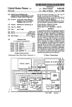
described. After the start (Block 151), at Block 152, the
started based upon a remote climate control handheld unit and
In some applications, the vehicle 121 may have a solar
caused to run for a run time period.
60
Block 154, a tactile indication is provided to a user to permit
the user to use the remote climate control handheld unit to
135 being recharged by the solar panel.
rechargeable battery 135 and that the remote climate control
At Block 153, an alert is sent to the remote climate control
handheld unit prior to expiration of the run time period. At
enable the electrically poWered climate control system 132
based upon the sensor 134 sensing the rechargeable battery
Those of skill in the art Will appreciate that the sensor 134
may also measure the current ?oWing in of or out of the
speaker 146'", and may not have a vibration unit. Other com
ponents of the remote climate control systems 120", 120'" are
similar to those described above With reference to FIG. 2.
Those components therefore need no further discussion
herein.
With reference to the ?owchart 150 of FIG. 11, a method of
operating a remote climate control system in a vehicle is
vehicle’s electrically poWered climate control system is
art.
panel, such as on the roof thereof, coupled to the rechargeable
battery 135. The remote climate controller 122 may also
120" (FIG. 9) may provide only a tactile indication through
the vibration unit 145", and may not have a speaker. In other
the electrically poWered climate control system 132.
coupled to an external poWer source 137. The external poWer
source 137 may be an electrical socket, a recharging station,
or other external poWer source as knoWn to those skilled in the
Other components of the remote climate control system
120' are similar to those described above With reference to
FIG. 7. Those components therefore need no further discus
reset the run time period by sending a reset run time period
65
signal.
If a reset run time period signal is not received at Block 155,
the electrically poWered climate control system is shut off at


![Propagation des incertitudes et calcul de courbes [...]](http://vs1.manualzilla.com/store/data/006372949_1-db4edaa1f40c36a53793e9d10310ce6a-150x150.png)