1
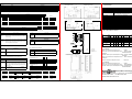
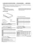
ver 2009-12-31-01
2 Phase Micro Step Motor Driver
MDC2516 User Manual
!
Dangereou
1.Do not contact the inside of the driver. Electric shock and injury may occur.
2.Be sure to connect the earth with the case of the driver and motor. Electric shock and injury
may occur.
3.Switch the power off before installing, moving, inspecting, or maintaining the driver.
4.Never connect/disconnect the motor connector and wires when power is applied.
5.Do not contact the rotating parts of motors.
!
1. Use the precaution
6.Output/input signal circuit
2.The confirmation of content
7.Connecting diagram
3.Store and install
8.Diemsnsions
4.The sunmary
9.Specifications
5.Introduction of the panel
10.Leads of motor connection
Please read and be familiar with the notices of specification and
security
in user manual before to use the driver. Please reserve this user
manual
3.3 Install the way and space of assembly
3.3.1 Install the way
Use two pcs M3 screws to fixed the aluminium to ventilate well place.
Attention
1.Do not use the product at the place where is probable to get wet, or in inflammable, explosive
circumstance.Electric shock, fire ormalfunctions, and damage may occur.
2.Keep ventilative to the drive for heat dissipation. Avoid things obstructing the exhaust window
and keep distance with other devices.
3.Wire correctly as indications and mount the motor on incombustible metal material to avoid
shake or impact.
4. Use DC independently as the power input. Do not connect with other devices such as relay or
magnetic valve to avoid interference.
5.Run with good ventilation (implement of fan is suggested) while applying voltage higher than
30V DC or constant current higher than 3A. Overheat may occur.
6.Motor, drive and relatives should be well fastened before trial run.
7.Motor, drive and relatives should be well fastened before trial run.
8.If any abnormalities occur in operation, check throughly and do not restart the motor before
safety is confirmed.
9.Do not touch the motor, case and other conponents once power failure occurs. High temperature
and high voltage might still exist.
10.Emergency stop system is suggested to add with the motor tranportion facility.
!
3.3.2 Space of assembly
In order to use and cool the result well, driver with close object must keep
enough 25mm(up). The following picture shows.
Attention
1.We suggest to check or replace elements, such as condensers and transistors etc.,of the drive
power wiring every five years. The equipment might be out of order or damaged because of
aging attenuation.
Prohibited
!
1. Don't take apart the driver when breakdown.
Please handed over to the agent.
1. Use the precaution
★ Suitable range
Our product is design for general industrial, not suitable for with having great influence on
safety of life as vehicle transporting or medical apparatus.
★ Warranty range
2. The confirmation of content
The content of package is listed below for confirmation, please check out after
taking off a seal, if any damage or lack, please contact us at once.
◎ The driver
◎ 3.5mm terminal
◎ screws
◎ user manual
Unit
1 piece
1 package
1 book
Warranty is one year after buying from Hanmark or distributor.
3.Storage and Installation
★Avoid the responsibility item
Following item don't belong to warranty range
①take apart the drive, repair or transform by oneself.
②The use of environment or terms are not fit in with drive specifications.
③Unsuitable to use the drive, make the drive breakdown.
④Breakdown not caused from the defect of the design or manufacture of the product.
⑤Breakdown due to responsibility exclusive events, such as misuse, abuse, accident, act of god,
or any natural calamity.
★ Safety Cautions
①These SAFETY CAUTIONS are classified into three grades: "DANGER", "CAUTION",
and "PROHIBITED", which will be well interpreted later. Please follow the indications to avoid damages or injury.
②Read the Operation Manual thoroughly prior to the use (placement, operation, maintenance
and inspection) to put the product in use properly.
!
!
DANGER: safety caution given when incorrect handling could result in hazardous
situation involving the possibility of death or serious injury.
CAUTION: safety caution given when incorrect handling could result in hazardous
situations involving the possibility of moderate or light injury or damage to property.
PROHIBITED: Indicates what shall not be done.
25mm
3.1 Storage
To meet the warranty and extend the product life, store the product as following
instructions while not used.
① Store in the original package as possible
② Keep the storage place clean and dry. The proper temperature is between -20℃~50℃,
and proper humidity is lower than 80%.
③ Avoid to exposure under greased and corrosive atmosphere. Well packaged and put
on shelf.
④ Prevent the body of the machine from impact or shake.
3.2 Installation environment
① Places far away from mist, steam, corrosive atmosphere, ignitable gas, comburstibles,
floatingt. metal or greased dust.
② Operating temperature: 0℃~40℃. Environment humidity: lower than 90% and no
condensation.
③ Use DC independently as the power input. Do not connect with other devices such
as relay or magnetic valve to avoid interference.
④ Places without EMI noise and electric leakage.
⑤ Ventilate if the motor temperature over 70℃.
⑥ Avoid to install at places where the motor might be shocked or with continuous shake.
Impact guidance system is necessary for such places.
25mm
25mm
4. The summary
A. Low vibration, high resolution, suitable for smoothly applications.
B. DC18~80V Power input (curent>4A)。
C. Can adjust and operate the current,0.5~4.0A/phase.
D.
E.
F.
G.
H.
I.
J.
Driving method is constant bi-polar current, match 2 phase motors of 4 or 6 or 8 lead wire.
Two methods of pulse input, Single-pluse (1P) and Two-pulse (2P).
Alarm (ALM) output signal function.
External current off (COF) function.
Driving the micro step drive, just use the normal 2 phase step motor.
Input and ouptut both use Photo coupler to provide noise isolation.
Resolution 200、400、500、800、1000、1600、2000、3200、5000、6400、
10000、12800、25000、25600、50000、51200。
5. Introduction of the panel
1. Green/ Red LED
2. 4PIN Current setting switch
3. 2PIN Stop current setting
switch
4. 10 PIN 3.5mm terminal
5~6. 8PIN 3.5mm terminal
7. 6PIN Function setting
switch
6. Output / Input Signal Circuit
LED
PWR
CW
CCW
ALM
5.2
Name
Power light
Clock-wise light
Count clock-wise light
current overload light
Current Setting Switch
Name
RUN
PIN
DCBA
DCBA
Input signal circuit
Description
When the driver accept DC18~80V, PWR will be light.
Color
Green
Green
Green
Red
MDC2516
CONTROLLER
CONTROLLER
MDC2516
When the driver received one pulse signal, CW will be lgiht.
When the driver received one pulse signal, CCW will be lgiht.
When motor current overload, ALM will be light.
( up is 1,down is 0 )
P
short
Description
To set the drive current when motor run (0.5A~4.0A)
DCBA
9. Specifications
Output signal circuit
DCBA
DCBA
1.8A
2.2A
DCBA
DCBA
DCBA
DCBA
6.1 Pulse wave signal / Direction singal
1.0A
1.4A
DCBA
DCBA
1.2A
5.3
DCBA
1.6A
DCBA
2.0A
2.4A
2.6A
DCBA
2.8A
3.0A
DCBA
DCBA
3.2A
Stop Current Setting Switch
3.8A
3.4A
FE
3.6A
FE
DCBA
FE
4.0A
FE
1P input method seting
2P input method seting
input mode
up
input mode
cw pulse
up
up
Direction
Name
STOP
PIN
FE
Description
60%
To set percentage of current down (30%~60%)
5.4.1 Input Signal Terminal
50%
40%
30%
5.4.2 Output signal Terminal
Name
CW-
ALM+
CCW-
When 2P model, The pluse input terminal which have the
motor CCW.
When 1P model, The pluse input terminal which control
the running direction of the motor.
200,400,500,800,1000,1600,2000,3200,5000,6400,
10000,12800,25000,25600,50000,51200
Control Mode
Max Pulse Speed
Pulse Width
Direction Respond
Input Signal
Input Signal Impedance
Output Signal
Signal Type
Temperature
Moisture
Dimension (mm)
Weight (g)
Signal-Pulse(1P),Two-Pulse(2P)
400K Hz UP
2us (Min)
10us (Min)
+4~+10V, < 20mA
220Ω
Open Collector, 24V, 10mA(Max)
Open Collector
0~40°C
<85% RH
153.5(L)*91(W)*56(H)
660g
+5V
Description
pulse input
Wen the motor current overload, this point will output a signal.
CW
CW
ALM-
Direction
Phase
Model
VEXTA
TAMAGAWA
SANYO
TECO
TECO
CCW
CCW
Name
COF+
Resolution
PWM Constant Bi-Polar Current
DC18~80V@4A
1.0~4.0A/phase
Dreve MDC2516
Excitation off input
CCW+
ccw pulse
up
2 phase micro step motor driver /MDC2516
10. Leads of Motor Connetio
Name
Description
When 2P mode, The pluse input terminal which have the
motor CW.
When 1P mode, The pluse input terminal which have the
motor running.
up
u
7. Connecting Diagram
up
User's interface
CW+
cw pulse
Item / Model
Drive Method
Power
Drive Current
Description
When add a high voltage in this point, the current of the drive
would down to zero at once.
COF-
COF
COF
+5V
Alarm output
錯誤訊號出力
TECO
ALM
ALM
A
6
6
6
6
6
Leads
8
Leads
/A
Black
Black
Black
Black
Red
Green
Green
Green
Green
Red
White
Red Black
B
Red
Red
Red
Red
Green
/B
Blue
Blue
Blue
Blue
Green
White
Green Yellow
CA
CB
Yellow
Yellow
Yellow
Yellow
White
White
White
White
Black
White
Red,White
Black,White
Green,White
Yellow,White
5.5 DC Input Signal Terminal
Name
5.6 Motor Wiring Terminal
Description
Power DC18~80V @4A ; positive input.
Name
+A
-A
V+
Power negative input.
+B
-B
V-
Motor A phase
Motor /A phase
Motor B phase
Motor /B phase
5.7 Function Setting Switch (up is 1,down is 0)
2P Pluse Wave Input
Name
KLMN
ACD
/OFF
Description
To choose driver resolution of step.
Name
Auto current down switch.
When
motor stops, ACD is used for driving auto current
down. OFF is used for fixed driving current when
motor stops.
CW
CCW
Description
KLMN
200
KLMN
800
Pulse wave input.
Down is 1P.
KLMN
1600
Up is 2P,
KLMN
6400
KLMN
KLMN
3200
12800
KLMN
25600
KLMN
51200
KLMN
400
KLMN
500
Description
KLMN
1000
5000
KLMN
2000
KLMN
10000
►DC Input 2 Phase Step Motor Driver........... ....SD200
►AC110V Input 2 Phase Step Motor Driver........SD225 SD245 SD265
MSD228 MSD248
MSD268
►AC85~260V Input 2 Phase Step Motor Driver...SD2202 MSD2204
MSD2206
►DC Input 2 Phase Micro Step Motor Driver.......MD26 MDC2116
MDC2516
►DC Input 5 Phase Step Motor Driver................SD520
►AC110V Input 5 Phase Step Motor Driver.. .....SD500 MSD508
►AC85~260V Input 5 Phase Step Motor Driver...SD528 SD528F-2.8A
MSD558 MSD568
CLOCK pulse input terminal
DIRECTION pulse input terminal
KLMN
GND -
【2 Phase】
DC current
DC 18~80V
CURRENT> 4A
【5 Phase】
1P Pluse Wave Input
CW
CCW
8. Dimensions ( unit:mm )
VDC+
►AC 2 Phase Micro Step Motor Driver...............MAC7516
CW pulse input terminal
CCW pulse input terminal
Name
1P
/2P
+A
-A
+B
-B
Description
KLMN
25000
KLMN
50000
Hanmark Drive Technology Co.,
Address:No.189. Longshou St., Taoyuan City, 330 Taiwan R.O.C
Tel:886-3-360-1689
Fax:886-3-360-1768
website:www.hanmark.com.tw