1
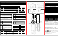
6. Output / Input Signal Circuit
LED
PWR
CW
CCW
ALM
5.2
Name
Power light
Clock-wise light
Count clock-wise light
current overload light
Current Setting Switch
Name
RUN
PIN
DCBA
DCBA
Input signal circuit
Description
When the driver accept DC18~80V, PWR will be light.
Color
Green
Green
Green
Red
MDC2516
CONTROLLER
CONTROLLER
MDC2516
When the driver received one pulse signal, CW will be lgiht.
When the driver received one pulse signal, CCW will be lgiht.
When motor current overload, ALM will be light.
( up is 1,down is 0 )
P
short
Description
To set the drive current when motor run (0.5A~4.0A)
DCBA
9. Specifications
Output signal circuit
DCBA
DCBA
1.8A
2.2A
DCBA
DCBA
DCBA
DCBA
6.1 Pulse wave signal / Direction singal
1.0A
1.4A
DCBA
DCBA
1.2A
5.3
DCBA
1.6A
DCBA
2.0A
2.4A
2.6A
DCBA
2.8A
3.0A
DCBA
DCBA
3.2A
Stop Current Setting Switch
3.8A
3.4A
FE
3.6A
FE
DCBA
FE
4.0A
FE
1P input method seting
2P input method seting
input mode
up
input mode
cw pulse
up
up
Direction
Name
STOP
PIN
FE
Description
60%
To set percentage of current down (30%~60%)
5.4.1 Input Signal Terminal
50%
40%
30%
5.4.2 Output signal Terminal
Name
CW-
ALM+
CCW-
When 2P model, The pluse input terminal which have the
motor CCW.
When 1P model, The pluse input terminal which control
the running direction of the motor.
200,400,500,800,1000,1600,2000,3200,5000,6400,
10000,12800,25000,25600,50000,51200
Control Mode
Max Pulse Speed
Pulse Width
Direction Respond
Input Signal
Input Signal Impedance
Output Signal
Signal Type
Temperature
Moisture
Dimension (mm)
Weight (g)
Signal-Pulse(1P),Two-Pulse(2P)
400K Hz UP
2us (Min)
10us (Min)
+4~+10V, < 20mA
220Ω
Open Collector, 24V, 10mA(Max)
Open Collector
0~40°C
<85% RH
153.5(L)*91(W)*56(H)
660g
+5V
Description
pulse input
Wen the motor current overload, this point will output a signal.
CW
CW
ALM-
Direction
Phase
Model
VEXTA
TAMAGAWA
SANYO
TECO
TECO
CCW
CCW
Name
COF+
Resolution
PWM Constant Bi-Polar Current
DC18~80V@4A
1.0~4.0A/phase
Dreve MDC2516
Excitation off input
CCW+
ccw pulse
up
2 phase micro step motor driver /MDC2516
10. Leads of Motor Connetio
Name
Description
When 2P mode, The pluse input terminal which have the
motor CW.
When 1P mode, The pluse input terminal which have the
motor running.
up
u
7. Connecting Diagram
up
User's interface
CW+
cw pulse
Item / Model
Drive Method
Power
Drive Current
Description
When add a high voltage in this point, the current of the drive
would down to zero at once.
COF-
COF
COF
+5V
Alarm output
錯誤訊號出力
TECO
ALM
ALM
A
6
6
6
6
6
Leads
8
Leads
/A
Black
Black
Black
Black
Red
Green
Green
Green
Green
Red
White
Red Black
B
Red
Red
Red
Red
Green
/B
Blue
Blue
Blue
Blue
Green
White
Green Yellow
CA
CB
Yellow
Yellow
Yellow
Yellow
White
White
White
White
Black
White
Red,White
Black,White
Green,White
Yellow,White
5.5 DC Input Signal Terminal
Name
5.6 Motor Wiring Terminal
Description
Power DC18~80V @4A ; positive input.
Name
+A
-A
V+
Power negative input.
+B
-B
V-
Motor A phase
Motor /A phase
Motor B phase
Motor /B phase
5.7 Function Setting Switch (up is 1,down is 0)
2P Pluse Wave Input
Name
KLMN
ACD
/OFF
Description
To choose driver resolution of step.
Name
Auto current down switch.
When
motor stops, ACD is used for driving auto current
down. OFF is used for fixed driving current when
motor stops.
CW
CCW
Description
KLMN
200
KLMN
800
Pulse wave input.
Down is 1P.
KLMN
1600
Up is 2P,
KLMN
6400
KLMN
KLMN
3200
12800
KLMN
25600
KLMN
51200
KLMN
400
KLMN
500
Description
KLMN
1000
5000
KLMN
2000
KLMN
10000
►DC Input 2 Phase Step Motor Driver........... ....SD200
►AC110V Input 2 Phase Step Motor Driver........SD225 SD245 SD265
MSD228 MSD248
MSD268
►AC85~260V Input 2 Phase Step Motor Driver...SD2202 MSD2204
MSD2206
►DC Input 2 Phase Micro Step Motor Driver.......MD26 MDC2116
MDC2516
►DC Input 5 Phase Step Motor Driver................SD520
►AC110V Input 5 Phase Step Motor Driver.. .....SD500 MSD508
►AC85~260V Input 5 Phase Step Motor Driver...SD528 SD528F-2.8A
MSD558 MSD568
CLOCK pulse input terminal
DIRECTION pulse input terminal
KLMN
GND -
【2 Phase】
DC current
DC 18~80V
CURRENT> 4A
【5 Phase】
1P Pluse Wave Input
CW
CCW
8. Dimensions ( unit:mm )
VDC+
►AC 2 Phase Micro Step Motor Driver...............MAC7516
CW pulse input terminal
CCW pulse input terminal
Name
1P
/2P
+A
-A
+B
-B
Description
KLMN
25000
KLMN
50000
Hanmark Drive Technology Co.,
Address:No.189. Longshou St., Taoyuan City, 330 Taiwan R.O.C
Tel:886-3-360-1689
Fax:886-3-360-1768
website:www.hanmark.com.tw