1
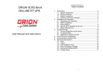
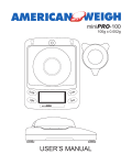
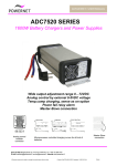
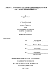
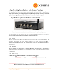
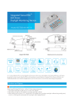
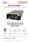
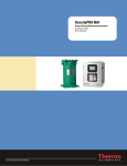
DATASHEET / USER MANUAL MSR 2400R Rugged Power System for Military and Heavy Duty Applications 2400 W modular power system Approved for heavy environment Power supply or battery charging systems Parallel n+1 connection, up to 90A Series connection, up to 360VDC Multi outputs, ± outputs Hot-swap plug-in modules Module fail and mains alarms Operating temperature –40oC … +55 °C Vibration, sin, IEC60068-2-6, 20-50m/s2 (2-5 gn) Vibration, broad-band random, IEC60068-2-64 Bump, IEC60068-2-29, 250m/s2 (25 gn) Shock, IEC60068-2-27, 400m/s2 (40 gn) Cold test, IEC60068-2-1 Damp heat, cyclic, IEC60068-2-30 Dry heat, IEC60068-2-2 19” SUB-RACK UNITS Type Voltage versions MSR7110R/48 MSR7110R/96 24V, 36V, 48V 72V, 96V 8171178A Cover plate for empty module place Modules per rack 1…3 pcs 1…3 pcs Power Mechanics (w x h x d) 800W…2400W 800W…1800W 19” (482mm) / 2U (88mm) / 360mm 19” (482mm) / 2U (88mm) / 360mm 25TE / 2U RECTIFIER MODULES Type Input voltage *) ADC7180R/12 ADC7180R/24 ADC7180R/36 ADC7180R/48 ADC7180R/72 ADC7180R/96 50…260 VAC 50…260 VAC 50…260 VAC 50…260 VAC 50…260 VAC 50…260 VAC Nominal Output Voltage 12 VDC 24 VDC 36 VDC 48 VDC 72 VDC 96 VDC Voltage Setting Range 12-15VDC 24-30VDC 36-54VDC 48-60VDC 72-108VDC 90-144VDC Max Output Current 30 A 30 A 20 A 15 A 10 A 7.5A Current Limit Setting 0-30A 0-30A 0-20A 0-15A 0-10A 0-7.5A Max Power 800W 800W 800W 800W 800W 800W Mechanics (w x h x d) 25TE / 2U / 230mm 25TE / 2U / 230mm 25TE / 2U / 230mm 25TE / 2U / 230mm 25TE / 2U / 230mm 25TE / 2U / 230mm *) Max power 600W at DC input, reduced power 55…200VAC or 78…200VDC Powernet Oy Martinkyläntie 43, FI-01720 VANTAA, Tel. +358 10 2890 700 E-mail [email protected], [email protected] Internet www.powernet.fi We reserve the right to change the specification without notice Created: 21.09.2012 TRä/RLi Update 17.03.2015 HLI File: 711cR0f.doc DATASHEET / USER MANUAL INPUT Input voltage Frequency Safety Input current Inrush current Isolation 55…264 VAC 78…360 VDC / max 600W Mains switch Soft start Input / ground Input / outputs Output / ground Front panel with light Mains input connector Common input for each rectifier OUTPUT Voltage Current Short circuit protection MCBs on front panel 55…200VAC reduced power, see module datasheet 78…200VDC reduced power, see module datasheet 45...65Hz According to EN60950, Class I Max 4.5A per module max 7A 10ms peak, otherwise less than 4.5A 1500VAC 3750VAC 500VDC 12, 24, 48VDC One per PSU 72, 96VDC One per sub-rack, max 10A current IEC320 C14 male connector 12…120VDC / max 800W per module 0…30A / max 800W per module Short circuit protected, electronic current limit 3 x 30A MCB in negative output 3 x 10A MCB in negative output Output connector 3-pole 10mm2 screw terminal for each rectifier (+ , - , PE) Hot swap Series diode in each rectifier Hot-swap allowed, Input and output switch at OFF position Series/parallel operations All modules can be connected in series or in parallel CONTROLS Input Output ALARMS Input failure Output failure Alarm connector Nominal voltages Nominal current per module Rectifier modules ADC7110R/48 sub-rack ADC7110R/96 sub-rack 3 terminal groups on rear panel On the front panel On the front panel Power switch with ON/OFF light MCB ON/OFF safety switch U in nom < appr. 150VAC Module failure or output switch off Rear panel Pin configurations Normally open and closed relay contacts Relay contact and MCB auxiliary relay Removable 12-pole 2.5mm2 screw terminal 1 2 3 4 5 6 7 8 9 10 11 12 ENVIRONMENTAL Temperature range Cooling Shock and vibration Operating Storage ADC7180R modules IEC60068-2 We reserve the right to change the specification without notice Mains alarm COMMON Mains alarm NO Mains alarm NC Parallel output alarm COMMON Parallel output alarm NO *) Series output alarm PSU1 COMMON Series output alarm PSU1 NC *) Series output alarm PSU2 COMMON Series output alarm PSU2 NC *) Series output alarm PSU3 COMMON Series output alarm PSU3 NC *) *) Normally = Mains / PSU OK Not in use -40°C...+70 °C, de-rating at +50°C...+70 °C -40°C...+85 °C Temperature controlled fan in front panel See approvals below Created: 21.09.2012 TRä/RLi Update 17.03.2015 HLI File: 711cR0f.doc DATASHEET / USER MANUAL STANDARDS / APPROVALS Safety EN60950 Class I EMC emissions EN50081-1 Main standard EN55022 class B Conducted emissions 150 kHz …30 MHz Radiated emissions 30 MHz … 1000 MHz EN50082-2 Main standard EN61000-4-2 EN61000-4-3, ENV50204 EN61000-4-4 EN61000-4-5 EN61000-4-6 EN61000-4-8 EN61000-4-11 Electrostatic Discharge Electromagnetic field immunity Fast Transients Surge Conductive Immunity Power Frequency Magnetic Field Power Line Quality EN61000-3-2 EN61000-3-3 Harmonic Currents Emissions Voltage Fluctuation and Flicker Sensation Environmental IEC60068-2 Main Standard Vibration sinusoidal Vibr. broad-band random Bump Shock Cold test Damp Heat, Cyclic Dry Heat IEC60068-2-6, Test Fc IEC60068-2-64, Test Fh IEC60068-2-29, Test Eb IEC60068-2-27, Test Ea IEC60068-2-1, Test Ab IEC60068-2-30, Test Db IEC60068-2-2, Test Bb 20m/s2 (2gn) 9-200Hz, 50m/s2 (5gn) 200-500Hz Spectral acceleration 3.57gnrms 5-500Hz 250m/s2 (25gn) 6ms 400m/s2 (40gn) 6ms -40oC 3 oC, transportation and operation +55oC 2 oC, transportation and operation +70oC 2 oC, transportation and storage 19” sub-rack Height Width Depth Rack without rectifiers Rectifier Steel Positions for 3 pcs of ADC7180 modules 2U 19” 300mm, excluding handles and connectors 5.5 kg 1.35kg IP20 EMC immunity Product Family Standard MECHANICAL Power Rack Dimensions Weight Enclosure Installation space for wires We reserve the right to change the specification without notice Created: 21.09.2012 TRä/RLi Update 17.03.2015 HLI File: 711cR0f.doc DATASHEET / USER MANUAL Operating and connecting the sub-rack and modules General MSR7110R sub-racks have be developed can be used to supply several output voltages from 0V up to 400VDC in series connection. MSR7110R sub-racks can be used to supply several output voltages from 0V up to 400VDC in series connection. Modules can be connected in parallel, series or to have multi output voltages from the same sub-rack. Units are hot swappable, but the sub-rack also have both input and output switch to make the change without power. 1…3 pcs of modules can be installed in the sub-rack. Empty module places are covered by the cover plate. Mounting the sub-rack Sub-rack is installed in 19” cabinet and mounted by 4pcs of M6 screws from the front panel. Mounting the plug-in module The plug-in module is installed by pushing it to the bottom of sub-rack as long as the connector in the rear panel have the contact with the mating connector in sub-rack. Mounting screws in modules front panel are fastened. Removing the module is made in opposite order. Mains connection The mains is supplied by IEC320 C14 male connector. Use 1-phase power cords cross-section 3 x 1,5mm2. The minimum mains fuse is 16A. Make sure that both input and output are switched off in the front panel of sub-rack before connecting the mains. Turn the mains switch to up position. The switch light indicates that mains is connected. The unit is starting about 4 seconds. The unit’s output led in front panel is lightning green. Output connection Use minimum 4mm2 output cable, 6mm2 preferred. Connect cables to the screw terminal in the sub-rack’s rear panel via the cable clamp. Output MCBs can be turned to the ON position after module’s output led in front panel is green. Outputs can be in stand-alone, parallel or series use. 1. Stand-alone use Connect minimum 4mm2 cables from modules + and - screw terminal to load. 2. Parallel use Connect each module to the load by minimum 4mm2 cables. To ensure proper load sharing the length and cross section of each output cable need to be the same and the output adjustment at each module should be equal. 3. Series use The series connection is made by connecting the positive output of module 1 to the negative output of module 2 and connecting the load between the positive output of module 2 and negative output of module 1. Use minimum 4mm2 cables. Output voltage adjustment The factory setting for the output is the nominal voltage (for example 48VDC). Output of each module can be adjusted by turning Uadj trimmer. The adjustment is made by small screw driver. Output current limit adjustment The factory setting for the current limit is the nominal output current . Output current limit (max current) can be adjusted from the Iadj trimmer. Alarms Potential free change over relay contacts (NO, NC, COM) are included in system. We reserve the right to change the specification without notice Created: 21.09.2012 TRä/RLi Update 17.03.2015 HLI File: 711cR0f.doc DATASHEET / USER MANUAL Input alarm Input alarm is indicated when mains reduce below 150V. Both normally open contact between pins 1-2 and normally closed contact between pins 1-3 are available. Module fail or output MCB fail Each rectifier have module fail relay alarm NO and NC contact. Standard sub-rack includes NC contacts from each rectifier and parallel connected common alarm from whole system with NO contacts. Parallel connected NO contacts are in use when switch S4 is in NO position. Common alarm can be now connected between pins 4-5. If the switch S4 is in NC-position (serial alarm), output alarms of each PSU can be used individually from pins 6-7, 8-9 and 10-11 or to these individual alarms can be connected in series and the common NC output can be taken out between pins 6 – 11. The status normal means the normal operating condition for the power supply. The cross section of alarm cable can be 0,22 … 0,75mm2. Electrical connections in the sub-rack Voltage versions 12VDC, 24VDC and 48VDC We reserve the right to change the specification without notice Created: 21.09.2012 TRä/RLi Update 17.03.2015 HLI File: 711cR0f.doc DATASHEET / USER MANUAL Electrical connections in the sub-rack Voltage versions 72VDC and 96VDC Pin Configuration in rear panel We reserve the right to change the specification without notice Lead through position for analog control cable Created: 21.09.2012 TRä/RLi Update 17.03.2015 HLI File: 711cR0f.doc