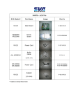
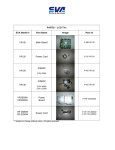
1
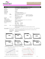
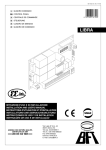
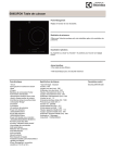
DATASHEET / USER MANUAL ADC7480 SERIES 3000W Battery Chargers and Power Supplies Wide output adjustment range 0…320VDC Analog control by external 0-5VDC voltage Temp.comp charging, sense as on option Power fail relay alarm Master-Slave connection Analog control modular connector Microprocessor controlled charging curves for all kind of batteries Master-Slave connection Sales & R&D Martinkyläntie 43, FI-01720 VANTAA, Tel. +358 10 2890 700 E-mail [email protected], [email protected] Internet www.powernet.fi Powernet reserves the right to change the specification without notice Created: JMa/TRä 08.06.2012/ Updated: 19.08.2015 HLi 748c5o DATASHEET / USER MANUAL POWER SUPPLIES AND BATTERY CHARGERS, TRIMMER ADJUSTABLE Input voltage range Nominal Voltage Nominal Current Max Type **) ADC7480/12 ADC7480/24 ADC7480/36 ADC7480/48 ADC7480/72 ADC7480/110 ADC7480/160 ADC7480/220 70-264VAC/80-369VDC 70-264VAC/80-369VDC 70-264VAC/80-369VDC 70-264VAC/80-369VDC 70-264VAC/80-369VDC 70-264VAC/80-369VDC 70-264VAC/80-369VDC 70-264VAC/80-369VDC output voltage setting range 12 VDC 24 VDC 36 VDC 48 VDC 72 VDC 110 VDC 160 VDC 220 VDC 0-18 VDC 0-36 VDC 0-54 VDC 0-72 VDC 0-108 VDC 0-165 VDC 0-230 VDC 0-320VDC output current 200 A 127 A 95 A 64 A 42 A 25 A 20 A 14 A setting range 0-200A 0-127A 0-95A 0-64A 0-42A 0-25A 0-20A 0-14A Installation / dimensions (Width x Height x Depth, mm) power **) 3000W 3200W 3200W 3200W 3200W 3200W 3200W 3200W Wall/Bench 400x250x80 mm Wall/Bench 400x250x80 mm Wall/Bench 400x250x80 mm Wall/Bench 400x250x80 mm Wall/Bench 400x250x80 mm Wall/Bench 400x250x80 mm Wall/Bench 400x250x80 mm Wall/Bench 400x250x80 mm ANALOG CONTROLLABLE MODELS BY EXTERNAL 0-5VDC VOLTAGE Input voltage range Nominal Voltage Nominal Current Max Type *) ADC7480/12AI ADC7480/24AI ADC7480/36AI ADC7480/48AI ADC7480/72AI ADC7480/110AI ADC7480/160AI ADC7480/220AI **) 70-264VAC/80-369VDC 70-264VAC/80-369VDC 70-264VAC/80-369VDC 70-264VAC/80-369VDC 70-264VAC/80-369VDC 70-264VAC/80-369VDC 70-264VAC/80-369VDC 70-264VAC/80-369VDC output voltage setting range 12 VDC 24 VDC 36 VDC 48 VDC 72 VDC 110 VDC 160 VDC 220 VDC 0-18 VDC 0-36 VDC 0-54 VDC 0-72 VDC 0-108 VDC 0-165 VDC 0-230 VDC 0-320VDC output current 200 A 127 A 95 A 64 A 42 A 25 A 20 A 14 A setting Range 0-200A 0-127A 0-95A 0-64A 0-42A 0-25A 0-20A 0-14A Installation / dimensions (Width x Height x Depth, mm) power **) 3000W 3200W 3200W 3200W 3200W 3200W 3200W 3200W Wall/Bench 400x250x80 mm Wall/Bench 400x250x80 mm Wall/Bench 400x250x80 mm Wall/Bench 400x250x80 mm Wall/Bench 400x250x80 mm Wall/Bench 400x250x80 mm Wall/Bench 400x250x80 mm Wall/Bench 400x250x80 mm BATTERY CHARGERS WITH TEMPERATURE COMPENSATION Type Input voltage range *) **) ADC7480/12T ADC7480/24T ADC7480/36T ADC7480/48T ADC7480/72T ADC7480/110T ADC7480/160T ADC7480/220T 70-264VAC/80-369VDC 70-264VAC/80-369VDC 70-264VAC/80-369VDC 70-264VAC/80-369VDC 70-264VAC/80-369VDC 70-264VAC/80-369VDC 70-264VAC/80-369VDC 70-264VAC/80-369VDC Output voltage factory setting 13.7 VDC 27.4 VDC 41.4 VDC 54.8 VDC 82.2VDC 123.3VDC 137VDC 246.6 VDC Programmed output voltages Output current (see table page 8) (see table) 3.3-18 VDC 12-28 VDC 13.7-42 VDC 13.7-60 VDC 27,4-82,5 VDC 82.2-137 VDC 82.2-219.2 VDC 109.6-287.7 VDC 200 A 127 A 95 A 64 A 42 A 25 A 20 A 14 A Max power **) 3000W 3200W 3200W 3200W 3200W 3200W 3200W 3200W Installation / dimensions (Width x Height x Depth, mm) Wall/Bench 400x250x80 mm Wall/Bench 400x250x80 mm Wall/Bench 400x250x80 mm Wall/Bench 400x250x80 mm Wall/Bench 400x250x80 mm Wall/Bench 400x250x80 mm Wall/Bench 400x250x80 mm Wall/Bench 400x250x80 mm *) Cable sets with modular connectors are included in packing: 1.5m cable set for analog control and 2.5m for or temp.comp models **) Reduced power 80…230VAC/VDC, see curves at next page If voltage version is more than 36V charger output is not SELV (Safety Extra Low Voltage) circuit. MODELS WITH POWER FAIL RELAY ALARM (24V models as a type number example) Type Option description Cable set ADC7480/24H ADC7480/24AIH ADC7480/24TH Trimmer adjustable model with power fail relay alarm Analog controllable model with power fail relay alarm Temp.comp model with Power fail relay alarm 1.5 m, modular connector Analog + relay cables Temp.comp + relay cables MASTER-SLAVE CONNECTION (24V models as a type number example) Master units ***) Slave units ADC7480/24 or ADC7480/24AI (optional for ADC7520/24T) ADC7480/24S serial bus control in and out Control to slave via serial bus**** ADC7480/24SH slave unit with relay, serial bus in only Cable set for master slave connection included in slave unit type number, 0.6m modular connectors in both ends ***) Master unit or slave with serial bus output can not include the relay alarm ****) TTL level serial bus, need level converter if use with standard RS-232 port CUSTOMISED VERSIONSON S • • • Cyclic battery chargers or customized charging curves for all kind of batteries Sense models Customized mechanics Powernet reserves the right to change the specification without notice Created: JMa/TRä 08.06.2012/ Updated: 19.08.2015 HLi 748c5o DATASHEET / USER MANUAL TECHNICAL DATA Input voltage 70…264 VAC (70…230VAC reduced power, see curve below) 80…369 VDC (80…230VDC reduced power) Efficiency 89% at full load, over 90% at 50% load (230VAC input) Input current 16A (max) Frequency 47-63 Hz Power Factor >0.95 Inrush current Soft start Output ripple <1% from output voltage, rms Mechanics Wall mounting, see dimensions first page Connectors Input Power cord, European schuko plug Output Models 12V, 24V, 36V, 48V copper bus bar terminals Model 72V 10 mm2 1.5m output cables Models 110V, 160V, 220V 6 mm2 1.5m output cables Option Options Modular connector Enclosure Aluminum case IP 20 Weight 7.1 kg without cables Output grounding Floating Ambient temperature -20°C…+45°C at full load, abs. max. +55°C, see curve below Over temperature protection Processor controlled on/off Over current protection Electrical current limit Reverse polarity protection With fuse Isolations Input - chassis 1500VAC Input - output 3750VAC Output - chassis 500VAC Standards Safety Class I IEC60950-1:2005(2nd Edition)+A1:2009 EN 60335-2-29:2004 +A2:2010 EN 60335-1:2002+A11:2004+A1:2004+A12:2006+A2:2006+A13:2008 EN 62233:2008 Note: If charger’s rated output voltage is higher than 36V it doesn’t fulfill article 10.101 (“The no-load d.c. output voltage shall not exceed 42,4V.”) EMC emissions Commercial and light-industrial environment EN61000-6-3, EN55022 Class B, EMC Immunity Industrial environment EN61000-6-2 Harmonics EN61000-3-2 Flickering EN61000-3-3 200 140 150 120 100 I [A] 50 U [V] 2 4 6 24V 72V 20 5 16 32 48 64 80 96 160V 10 U [V] 0 0 I [A] 15 110V 5 U [V] 0 0 25 50 75 100 125 150 U [V] 0 0 6 12 18 24 30 36 42 48 54 20 10 0 0 25 I [A] 15 U [ V] 10 48V 10 0 0 8 12 16 20 24 28 32 36 20 30 30 U [V] U [V] 4 25 I [ A] 36V 40 20 0 30 40 40 20 8 10 12 14 16 18 50 I [A] 50 0 0 60 60 40 20 0 I [A] 80 I [A] 80 60 12V 100 70 100 50 100 150 16 14 12 10 8 6 4 2 0 200 8 16 24 32 40 48 56 64 72 I [A] 220V U [V] 0 50 100 150 200 250 300 Nominal output voltage / current characteristics 3000W modules Output power / input voltage de rating curve Powernet reserves the right to change the specification without notice Output power / ambient temperature Created: JMa/TRä 08.06.2012/ Updated: 19.08.2015 HLi 748c5o DATASHEET / USER MANUAL INSTALLATION The location must be dry, dust-free, and indoors. The acceptable temperature range for operation is -20°C to +45°C. A higher ambient temperature will limit the current supply. CAUTION: The charger is not waterproof. Keep it dry and away from areas of high humidity to avoid the risk of electrical shock and damage to the charger. The equipment may be installed either vertically or horizontally. To ensure sufficient ventilation, leave approximately 10 cm of space around all air in- and outlets of the charger. Do not cover the equipment. Defined IP protection is reached if wall assembly used as instruction manual says. POWER SUPPLY / CHARGING OPERATION ← Ensure that the unit is switched off and that the environment meets the conditions described previous section ↑ Connect the output cables to the load / battery terminals: + cable to the + terminal and - cable to the - terminal. → Turn the power on by turning the switch to the I position. ↓ During the normal power supply operation / charging process the STATUS light will show a constant orange light. ° To avoid sparking, turn the power off before disconnecting the cables. CONNECTION WITH DC INPUT Wires in PSU’s power cable to be connected as follows: L DC input positive or negative N DC input negative or positive PE Ground OUTPUT VOLTAGE AND CURRENT LIMIT ADJUSTMENT Trimmer or analog control adjustable modules, type example ADC7480/24 or ADC7480/24AI: The output voltage and output current limit of the module can be adjusted as follows: Trimmer adjustable models: with the multi-turn potentiometer located on the front panel Analog controllable models by external 0-5VDC voltage, see detailed instructions Both voltage and current can be adjusted from zero to maximum value. Maximum 3200W output power is available within the adjustment range. Temp. comp. models, type example ADC7480/24T: Unit includes 16pcs of programmed output voltages, see temp. comp. models setting tables page. Any of these 16 different voltage settings can be taken in use. See instructions for choosing the programmed voltage. LED A orange LED indicates that the output of the charger module is healthy. RELAY ALARM Alarm relay indicates presence of AC input and charger failure. Both normally closed signals and normally open contacts are available. OUTPUT OVERCURRENT PROTECTION Output of the unit is protected against over current and short circuits by automatic, self-resetting electronic current limit. SERIES / PARALLEL CONNECTION Parallel operation: Passive load sharing. External series diodes are needed for redundant n+1 systems. Series operation: Up to 500V total voltage WARNING! Dangerous voltages, capable of causing death, are present in this equipment. Do not remove the cover. No operator serviceable parts inside. Refer servicing to qualified service personnel. Powernet reserves the right to change the specification without notice Created: JMa/TRä 08.06.2012/ Updated: 19.08.2015 HLi 748c5o DATASHEET / USER MANUAL SELECTION TABLE OF ADC7480 FEATURES This table shows which features are possible at the same time. IF N THEN then not possible. A n a L o g T r I m m er R e l a y B B T u u e s s m p O I ut n S e n s e S w i t c h Some of allowed combinations are optional. Contact manufacturer or your local distributor for further details. Trimmer adjustment Analog control (isolated) Relay alarm BusOut (serial bus control to slave) BusIn Temp.comp. Sense Customised charging algorithm chargers with code Switch N N N N N N C o d e N N N N N N N N N N PIN CONFIGURATION, MODULAR CONNECTORS FRONT PANEL REAR PANEL J43 J46 J47 J44 J69 J1 Relay Alarm option Digital serial bus out, control for external relay Digital serial bus in option Temperature compensation and Sense options Not in use (reserved factory testing) Analog control, isolated (for example type ADC7480/24AI) Powernet reserves the right to change the specification without notice Created: JMa/TRä 08.06.2012/ Updated: 19.08.2015 HLi 748c5o DATASHEET / USER MANUAL OPTIONAL ANALOG CONTROL VERSIONS, ISOLATED Analog control option allows full control for output current and voltages and it gives measured values for both of these. There is also available +5V internal power source for logic use. The analog input have 500V electrical insulation to power supply’s input and output. PIN CONFIGURATION, MODULAR CONNECTOR Interface to analog control card is made through AMP Modular 6 connector. It’s part number is 215-876-1. The product specification number is 108-19064 and application number is 114-19019. Part number for cable connector that fits to modular 6 is 737 336-1. Pin configuration: 1. Ground 2. Target value for current 3. Target value for voltage 4. Measured value for current 5. Measured value for voltage 6. +5V, (max 20mA) output Controlling analog card: All control voltages must be between 0 and 5 volts. Over 5V steering is not allowed. Logic for steering is positive so 5V in target value means maximum value from power supply and 0V means minimum output. If controlling connector is unplugged from modular connector, the power supply takes it’s minimum values for output. Measured values can be read from measured signals. Measured voltages are scaled equal as target values. If power supply lies on it’s voltage reference, then measured voltage should be equal as target. Same thing on current steering and it’s measured value. Measured signals (both together) can be loaded only 20mA or proper operation is not guaranteed. Modular connector is isolated from power supply’s input, enclosure and output terminals. That allows serial and parallel connection to separate power supply’s so that equal steering voltages are used. Number or connected devices are not limited. Only be sure that 500V insulation voltage is not exceeded. If connector in analog card is not a modular connector (9 pin D-connector), it is a different version of analog controlled power supply and this manual is not valid to it. Connection example, using internal +5VDC power source and external potentiometers: +5V output can be used to feed logic voltages for external circuits. Connection in an example works as a potentiometer controlled power supply. It is important to notice that +5V output is not allowed to load more then 20mA or proper operation is not guaranteed. Tuning instructions: Attention !!! Analog interface is tuned in a factory before it is delivered to customer. There should not be any reason for tuning if card is used between 0-5V voltage values. Qualified person is needed for tuning the device. Tuning can be done with a pair of digital multi meters and example schematic above. Procedure is following: ADC7480 front panel Location of tuning trimmers for analog control Trimmers are covered by sticker Powernet reserves the right to change the specification without notice 1. Adjust from potentiometers 5V to voltage target and 2V for current target. Connect digital voltage meter to power supply output. Tune from “Voltage Set” trimmer maximum output voltage to right value. 2. Connect digital voltage meter to Modular pin number 5. Tune from trimmer “Voltage Meas” so that digital voltage meter shows always equal value as is in pin 3 (target voltage). 3. Connect digital current meter to output so that it short-circuits the output. Now tune current target potentiometer to 5V. Tune from “Current Set” trimmer output current to value that is maximum value for device according to it’s specification. Be sure that your current meter has a right range. Do never exceed the current values that are specified for the device. If specified value is not known, take a contact to distributor. 4. Measure with digital multi meter voltage from Modular connector pin 4 Tune from trimmer ”Current Meas” to equal with voltage in modular pin 2 (Target Current). Created: JMa/TRä 08.06.2012/ Updated: 19.08.2015 HLi 748c5o DATASHEET / USER MANUAL OPTIONAL RELAY ALARM, TEMP.COMP, SENSE AND SERIAL BUS VERSIONS J43: pin1= Not connected J43: pin2= Relay contact common J43: pin3= Relay contact normally closed J43: pin4= Relay contact normally open J46: pin1= Relay control + J46: pin2= Serial bus gnd J46: pin3= Relay control gnd J46: pin4= Serial bus out col. (+) J47: pin1= Not connected J47: pin2= Serial bus gnd J47: pin3= Not connected J47: pin4= Serial bus in J44: pin1= Sense plus (+) J44: pin2= Temp sens (+) J44: pin3= Temp sens ( - ) J44: pin4= Sense minus ( - ) TEMPERATURE COMPENSATION MODELS, type number example ADC7480/24T The temp.comp cable enables the charger to adjust the output voltage in accordance with battery voltage and temperature fluctuations Temp.comp. / sense Modular connector See instructions for changing and adjusting the output voltage OPTIONAL MASTER SLAVE CONNECTION Using master power supply together with Slave unit. Master unit can be trimmer adjustable standard model ADC7480/24 or analog controllable model ADC7480/24AI (24V as an example). Note ! Unit with relay alarm, type exampleADC7480/24H can’t be used as a master unit. Slave unit is separate unit without adjustment possibility, type ADC7480/_ _ S. Connecting two or more ADC7480 units in series or parallel increases the output supply current or voltage. The output voltage and current of the master unit can be controlled by trimmers or by external analog control. The bus output from the master is connected to the first slave unit, which voltage / current equals to masters settings. More power can be provided by connecting more slave units to the chain. The connection principle is illustrated in the picture. Powernet reserves the right to change the specification without notice Created: JMa/TRä 08.06.2012/ Updated: 19.08.2015 HLi 748c5o DATASHEET / USER MANUAL PROGRAMMED VOLTAGES FOR TEMP.COMP. MODELS, type number example ADC7480/24T ADC7480/12T 12VDC 200A Code switch position 0 1 2 3 4 5 6 7 8 9 A B C D E F Nominal Battery voltage 6 VDC 6 VDC 6 VDC 12 VDC 12 VDC 12 VDC 12 VDC 12 VDC 12 VDC 12 VDC 12 VDC 12 VDC ADC7480/24T 24VDC 127A Voltage factory setting 3,3 VDC 5 VDC 6,75 VDC 6,85 VDC 6,9 VDC 12 VDC 13,4 VDC 13,5 VDC 13,6 VDC 13,7 VDC 13,7 VDC 13,7 VDC 13,8 VDC 13,9 VDC 14 VDC 15 VDC Output Current 200 A 200 A 200 A 200 A 200 A 200 A 200 A 200 A 200 A 200 A 133 A 67 A 200 A 200 A 200 A 200 A Factory default Voltage factory setting 13,7 VDC 24 VDC 27,4 VDC 34,25 VDC 36 VDC 40,2 VDC 40,5 VDC 40,8 VDC 40,95 VDC 41,1 VDC 41,1 VDC 41,1 VDC 41,25 VDC 41,4 VDC 41,7 VDC 42 VDC Output Current 95 A 95 A 95 A 95 A Factory default X Nominal Battery voltage 12 VDC 24 VDC 30 VDC 36 VDC 36 VDC 36 VDC 36 VDC 36 VDC 36 VDC 36 VDC 36 VDC 36 VDC 36 VDC 36 VDC maximum maximum maximum maximum maximum maximum X 63 A 31 A maximum maximum maximum maximum Nominal Battery voltage 24 VDC 36 VDC 48 VDC 60 VDC 60 VDC 60 VDC 60 VDC 60 VDC 72 VDC 72 VDC 72 VDC 72 VDC 72 VDC 72 VDC Voltage factory setting 27,4 VDC 41,1 VDC 54,8 VDC 60 VDC 67,5 VDC 68 VDC 68,5 VDC 68,5 VDC 68,8 VDC 72 VDC 81 VDC 81,6 VDC 82,2 VDC 82,2 VDC 82,2 VDC 82,5 VDC Output Current 42 A 42 A 42 A 42 A 42 A 42 A 42 A 21 A 42 A 42 A Factory default maximum maximum maximum X 28 A 14 A maximum ADC7480/160T 160VDC 20A Code switch position 0 1 2 3 4 5 6 7 8 9 A B C D E F Nominal Battery voltage 84 VDC 96 VDC 108 VDC 110 VDC 120 VDC 120 VDC 120 VDC 120 VDC 126 VDC 132 VDC 144 VDC 150 VDC 156 VDC 168 VDC 180 VDC 192 VDC 12 VDC 12 VDC 12 VDC 24 VDC 24 VDC 24 VDC 24 VDC 24 VDC 24 VDC 24 VDC 24 VDC 24 VDC 24 VDC 24 VDC Voltage factory setting 12 VDC 13,6 VDC 13,7 VDC 13,8 VDC 24 VDC 26,8 VDC 27 VDC 27,2 VDC 27,3 VDC 27,4 VDC 27,4 VDC 27,4 VDC 27,5 VDC 27,6 VDC 27,8 VDC 28 VDC Output Current 127 A 127 A 127 A 127 A 127 A Factory default maximum maximum maximum maximum maximum X 85 A 42 A maximum maximum maximum maximum Code switch position 0 1 2 3 4 5 6 7 8 9 A B C D E F Nominal Battery voltage 12 VDC 24 VDC 36 VDC 48 VDC 48 VDC 48 VDC 48 VDC 48 VDC 48 VDC 48 VDC 48 VDC 48 VDC 48 VDC 48 VDC Voltage factory setting 13,7 VDC 27,4 VDC 41,1 VDC 48 VDC 53,6 VDC 54 VDC 54,4 VDC 54,6 VDC 54,8 VDC 54,8 VDC 54,8 VDC 55 VDC 55,2 VDC 55,6 VDC 56 VDC 60 VDC Output Current 64 A 64 A 64 A 64 A Factory default maximum maximum maximum maximum maximum X 43 A 21 A maximum maximum maximum maximum maximum ADC7480/110T 110VDC 25A ADC7480/72T 72VDC 42A Code switch position 0 1 2 3 4 5 6 7 8 9 A B C D E F Nominal Battery voltage ADC7480/48T 48VDC 64A ADC7480/36T 36VDC 95A Code switch position 0 1 2 3 4 5 6 7 8 9 A B C D E F Code switch position 0 1 2 3 4 5 6 7 8 9 A B C D E F Code switch position 0 1 2 3 4 5 6 7 8 9 A B C D E F Nominal Battery voltage 72 VDC 80 VDC 84 VDC 96 VDC 96 VDC 96 VDC 96 VDC 96 VDC 108 VDC 108 VDC 108 VDC 108 VDC 108 VDC 108 VDC 110 VDC 120 VDC Voltage factory setting 82,2 VDC 91,3VDC 95,9 VDC 108 VDC 108,8 VDC 109,6 VDC 109,6 VDC 110,4 VDC 121,5 VDC 122,4 VDC 123,3 VDC 123,3 VDC 123,3 VDC 124,2 VDC 125,6VDC 137 VDC Output Current 25 A 25 A 25 A 25 A 25 A 25 A 13 A 25 A 25 A 25 A 25 A 17 A 8A 25 A Factory default X 25 A 25 A ADC7480/220T 220VDC 14A Voltage factory setting 95,9 VDC 109,6 VDC 123,3 VDC 125,6VDC 135 VDC 137 VDC 137 VDC 138 VDC 143,9VDC 150,7VDC 164,4VDC 171,3VDC 178,1VDC 191,8VDC 205,5VDC 219,2VDC Output Current 20 A 20 A 20 A 20 A 20 A 20 A 10 A 20 A 20 A 20 A 20 A Factory default X maximum maximum maximum maximum maximum Code switch position 0 1 2 3 4 5 6 7 8 9 A B C D E F Nominal Battery voltage 96 VDC 108 VDC 120 VDC 180 VDC 204 VDC 216 VDC 216 VDC 216 VDC 216 VDC 216 VDC 216 VDC 216 VDC 216 VDC 216 VDC 220 VDC 252 VDC Voltage factory setting 109,6 VDC 123,3 VDC 137 VDC 205,5 VDC 232,9 VDC 242 VDC 243 VDC 244 VDC 245 VDC 246,6 VDC 246,6 VDC 246,6 VDC 248 VDC 249,5 VDC 251,2VDC 287,7 VDC Output Current 14 A 14 A 14 A 14 A 14 A Factory default maximum maximum maximum maximum maximum X 10 A 5A maximum maximum maximum maximum Factory default code switch position by bold in tables Powernet reserves the right to change the specification without notice Created: JMa/TRä 08.06.2012/ Updated: 19.08.2015 HLi 748c5o DATASHEET / USER MANUAL INSTRUCTION TO CHANGE THE PROGRAMMED VOLTAGE FOR TEMP.COMP./SENSE MODELS, type number example ADC7480/24T ← Disconnect the power cord from the power line. ↑ Disconnect the output cables from the battery. → See the current code switch position of the unit. ↓ See new switch position code from the programmed output voltages sticker on the unit ° Rotate the code switch to the required position. Code switch The adjustment can be checked as follows: Short-circuit the output cables of the charger (output short circuit). Connect the charger to the power line. Follow the Status-led color. Switch ON the charger from the on/off switch. Count all the number of green blinks. There must be as much number of blinks as the code switch position number is. Note! If the position of the code switch is O, Status-led blinks only once and returns to red. The code switch positions A…F respond numbers 10…15 ☺ Now the charger has been adjusted! HINTS IF NOT SUCCEED You didn't have chance to count the number of blinks => You can start the test with the on/off switch of the charger again and count. You have made the wrong setting => Switch the charger off again and make the correct setting and count the blinking to check. You cannot find the required charging algorithm on list available => Contact the seller / importer and ask if the charger can be updated with the algorithm you need. Powernet reserves the right to change the specification without notice Created: JMa/TRä 08.06.2012/ Updated: 19.08.2015 HLi 748c5o