1
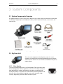
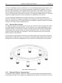
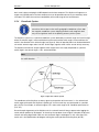
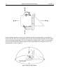
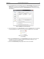
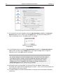
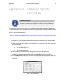
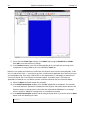
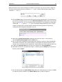
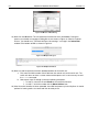
Table of Figures
v
Table of Figures
Figure 1: Typical System Components .........................................................................................................9
Figure 2: Brush and Slip Ring Layout......................................................................................................... 10
Figure 3: SkyScan Coordinate System ...................................................................................................... 11
Figure 4: Top-Down Coordinate System View ........................................................................................... 12
Figure 5: SkyScan in Parked Position ........................................................................................................ 12
Figure 6: SkyScan4 Shipping Locks .......................................................................................................... 19
Figure 7: Azimuth Window Plate ................................................................................................................ 20
Figure 8: Zenith Window Plate ................................................................................................................... 20
Figure 9: Correct DIP Switch Positions ...................................................................................................... 45
Figure 10: SD1000U Device Information Settings Page ............................................................................ 45
Figure 11: SD200 Device Information Settings Page ................................................................................. 46
Figure 12: SD200 Waiting for Connection .................................................................................................. 46
Figure 13: SD1000U Connection(out) Settings Page ................................................................................. 47
Figure 14: ParaniWIN Connection Successful Dialog ................................................................................ 47
Figure 15: SD1000U Device Setting Page ................................................................................................. 48
Figure 16: ParaniWIN Configuration Complete Dialog ............................................................................... 48
Figure 17: SMI Port Properties ................................................................................................................... 49
Figure 18: SMI View Layout........................................................................................................................ 50
Figure 19: SMI Hex String Entry ................................................................................................................. 51
Figure 20: SMI Response to X! ................................................................................................................... 51
Figure 21: SMI Browse for SMX File .......................................................................................................... 51
Figure 22: SMI Select Motor Dialog ........................................................................................................... 52
Figure 23: SMI Upload Progress ................................................................................................................ 52
Figure 24: SMI Upload Finished ................................................................................................................. 52