1
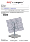
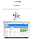
HELIOS ANALYTICS for positioner MICRO, TIV27C, TIV27E, TIV26A User Manual Document Rev. 13 dated 01-04-2015 Program you can download from: http://www.solar-motors.com/gb/monitoring-programs-d489.shtml _____________________________________________________________________________________ SAT CONTROL d.o.o., Pozenik 10, SI4207 CERKLJE SLOVENIA – EU www.solar-motors.com / [email protected] - Copy rights SAT CONTROL, all rights reserved! CONNECTING/DISCONNECTING of MICRO positioner: Colored connectors can be pulled out of positioner and plugged in, without screwing wires. Thought we suggest you make sure that all screws are tied properly on all wires on both ends of cables (on motor side and on positioner side). Be careful not to connect falsely as system might suffer damage. BUTTONS: Positioner Micro has two black buttons, one runs Motor A towards retracted position (in) and the other button runs Motor A towards extended position (out). Positioners POZSOL27x (OG+ trackers) also have buttons for manuals operation with same function. One button runs Motor A towards starting point and the other runs motor towards ending position. If you press both buttons at same time, red LED indicator will shine and manual operation will go into Axis B mode, where one button runs Motor B in and the other button runs Motor B out. After few seconds of inactivity mode automatically goes into Axis A mode. If you keep both buttons pressed for ~15 seconds, tracking mode will be enabled (No manual time setup is available at Micro). At TIV27x positioner you can set up time and enable tracking by driving motor into most perpendicular position and holding both buttons ~15s. Tipp: If tracking is enabled, motors will automatically return to sun-tracking position. If you wish the tracker to stay in position that was set manually, take transparent fuse out of the junction box or disconnect power supply. Attention: DO NOT run motors into retracted or extended position! Buttons are meant for testing and emergency use only. Note that all wiring is done before running motors! HELIOS ANALYTICS: The basic tracker operation is not conditioned by the use of a PC, but it provides additional functions that can be useful for advanced users. In addition, different parameters of solar tracker can be seen in this menu. CHANGING LANGUAGE: Language can be changed in drop down menu System, menu Settings. Available languages are English and German. Page 2 ATTENTION!! Changing values in the menu may influence the solar tracker operation! If you encounter problems with tracker, go to Chapter 50: Troubleshooting. Each white input field displays the current value, i.e., the solar tracker setting. Clicking in a particular input field turns the field yellow , what means you can change the value. As long as the input field is yellow, you can enter a new value in it. When you are satisfied with the new value, press »Enter«. Entered value will be sent to positioner, input field will turn white again and new (changed) value will be showed. Some input fields meant as indicators so values and could not be changed (for example: supply voltage display). In such fields, changing value will not take effect. CONNECTION: Positioner is connected to Helios via USB bus (default) or RS485 bus (optional). Use enclosed USB cable. In case, you use the direct USB A to USB B or Micro B cable you have to install VCP driver. Run and install the driver file named VCP_V1.4.0_Setup.exe. Note: for RS485 you will need a RS485 dongle on the PC side, as PC does not have RS485 standard port. Please refer to additional paper. RS485 dongle is not a part of solar tracker and you need to buy additionally. RS485 dongle have their own driver to create virtual com port – VCP. RS485 driver you can download from this link: http://www.solar-motors.com/files/USB2RS485_DRIVER/USB2RS485_Driver.zip Page 3 Helios top row Positioners Big white space one the left is a space where all positioners on communication bus are shown. When on USB, only one positioner will show. When on RS485 bus, up to 32 positioners can be shown, which can be picked with click. Files dropdown menu All values in fields can be exported into a file with extension “hss”. It is useful to backup current settings. It is also possible to import values from saved “hss” file. If you are unsure whether tracker’s settings are correct, you can verify by simple maneuver: Check motor label and find parameter “Mech. version” (newer motors) or “MW ver” (older motors). Parameters at newer versions go from MC1 upwards (MC1, MC2, …). Older versions are at separated by type (SM3, SM4S520M1, SM4S520M2, SM4S900M3) and those types have underclasses by number from 1000 upwards (1000, 1001, …). Applies to older version “MW ver.”: Basically, motors are the same with different markings. Translation table: http://www.solarmotors.com/files/INSTRUCTIONS_FOR_INSTALLATION_AND_USE/Mechanical%20versions%20-%20Translation%20table.pdf Find correct parameters in table Mechanical gears and common parameters: http://www.solarmotors.com/files/INSTRUCTIONS_FOR_INSTALLATION_AND_USE/Mechanical%20gears%20and%20common%20parameters.pdf Both tables are available under tab Support: http://www.solar-motors.com/gb/support-d24.shtml Another option is to verify motor’s “Mech. Version” or “MW ver” and import suitable *.hss file in Helios analytics, which are available under tab Support: http://www.solar-motors.com/gb/support-d24.shtml Page 4 System dropdown menu Menu includes two submenus: Settings and Locking. Submenu Settings includes parameters “Program settings” box, “COM port settings” box and “Custom position” box. Under “Program settings” Language and scan of RS485 IDs can be changed. Under “COM port settings” communication properties for RS485 bus can be changed (already pre-set). Under “Custom position” angle of three buttons in Helios Analytics main menu can be changed. Clicking on a button disables tracking and forces the position. See details in chapter 19. Submenu Locking is not relevant for regular users. Update Driving electronic (firmware) in solar tracker is upgradable. It means that we constantly improve the program, which is running in your product. Check for latest version on our web site http://www.solar-motors.com/, tab »support« or direct path: http://www.solar-motors.com/gb/support-d24.shtml. If newer version exists, download and save zip file to your local disk. Unzip the file to a known location. Update via Helios Analytics In Helios analytics program select menu Update, select correct COM port, browse for latest downloaded upgradable file (*.ehx) and press Update. Wait until transfer reaches 100% and click “Close”. If update is successful, new number of FW version will be shown. After upgrade procedure make sure to replace all “–nan” fields with “0” (Zero), if you don’t know the appropriate value. “-nan” fields can cause the system to malfunction. If update is not successful, update the positioner manually. Note: Described feature is available only for versions “B1” and higher. Lower versions need to be updated manually. See upgrading manuals below. Manual update is possible on new versions, too. Manuals for old boot loader releases: PC side: you must have the following files: "app_36_ver5.41.ehx or suntracer.ehx" (see note 1), “app_36_ver5.41.bat” (see note 1) and "update.exe". Save them all in same folder, i.e. c:\your_folder\ Page 5 Solar tracker controller side: Disconnect all power supplies from your controller. Press "W" button (button to run motor OUT) and connect your solar tracker controller to a PC (on USB port) with USB cable, which was included by solar tracker (orange LED must light). Then release the button and orange LED will be flashing (time limited to 1 minute). PC side: While LED is still flashing, click on “app_36c_ver5.41.bat” file. You will be asked for used COM port (you can see it in device manager), insert it and press enter. Transfer will begin, LED will turn off. At 100% upgrade is finished. Do you have problems with upgrading? Refer to www.solar-motors.com/files/Helios/Problems with upgrading - solutions.pdf Note 1: name.ehx or name.bat could be different. Described is just an example. Support Link to USB drivers page and Information window with our contact information. COM port Before getting any data from solar tracker, select correct COM port and click icon To disconnect, click icon Note: you need to have USB (VCP) driver installed. Drivers are included in the archieve file. Page 6 Monitoring tab Link Indicates communication status. If the value is incrementing, Helios has a stable connection to Solar tracker. Otherwise check cables, re-plug USB cable and restart Helios Analytics. SunTracer type Is type of electronic module inside the tracker. You will be asked after it when contacting our service team. SunTracer Version Is version of program running inside the positioner. This parameter will change after upgrade. Service Field shows service data, errors, mode etc.. Usupply Current supply voltage connected to solar tracker. Time Current SOLAR time for your location (see geo. longitude/latitude). Note that solar time could differ from your zone time. It is correct only for your accurate geo longitude. The range for hours is 0-23, and minutes 0-60. Hint: if you set geo. longitude to 0.0, time must completely equal with UTC time. Time zone: Parameter “Time zone“ applies to Sunrise and Sunset indication and has no effect on actual tracking. Day/month/Year Current date. Range of days is 1-31, months 1-12, of years 1970<. Longitude, latitude Indicate your geographical longitude and latitude (important for solar time calculation). Negative longitude values go western from Greenwich, negative latitude values go southern from equator (southern hemisphere). Page 7 Moving interval Means at what interval the solar tracker will correct its position to trace the sun. Possible values are from 60 to 900 seconds (1-15 minutes). If you check option “Resolution 0.1 degree” possible values are 1 ~ 900 seconds. »Sync time« button Pressing the »Sync time« button automatically sets the current time and date. If your time or date is incorrect (more than ten minutes), press the »Sync« button to open a wizard where you insert your local Longitude. Application automatically downloads G+MT time from your computer and writes it in the solar tracker memory. Note: The mean solar time used by the solar tracker is set for your geographical longitude, and differs from your zone time. Therefore do not change it after synchronizing. Enable, disable buttons Enable button enables tracking, Disable button disables tracking. H/V alignment button Pressing this button causes solar tracker to move in complete horizontal position. This is necessary during mechanically setup the tracker to align correct angles. Pre-set angles are: motor A = 0° and motor B = 90.0º. If panels (or mirror,…etc) are not in horizontal position after motor were stopped and some minor shift appear, you need to adjust mechanically (screws, clamps) to get proper horizontal position. For completely horizontal position, take spirit level as a sufficient measuring device. Custom position buttons These are predefined buttons with predefined angles. You can use them, for example, emergency park position in strong wind or high snow parking position for cleaning it from the panels or your custom park position. Pressing any of these buttons automatic tracking will become disabled and tracker will turn the panel into desired position. You can define all three buttons on your own: navigate to “System” and press “Settings”. Change text, angle A and angle B. See chapter 2. »Do reference A/B« buttons Use buttons to synchronize motors. In case of any change between real axes position and internal counters (impulses) or after mechanic/electronic service synchronization needs to be done. After pressing each button, motors run to its reference position (home). When motors stop, positioner is synchronized with actual motors position. Attention: If system is not synchronized when in tracking mode, motors could suffer severe damage! By clicking Do reference A/B, errors will be cleared automatically. Angle A, B Parameters show current angle for each tracker axis. Angle A usually means hour angle and angle B elevation. Hour angle has negative values in the morning and positive values in the afternoon. If you want to set tracker to specific angle, disable tracking, insert number into space “Angle” (in degrees) and press enter. Position, destination (A/B) Parameters show current and destination and position in impulses. Those values can only be used to diagnose the solar tracker operation. I motor, A,B Show current of each motor at that moment. Manual movements with buttons With 4 red buttons you can manually move both axes. If you wish to move axes manually by arrows or inserting angle, Automatic tracking must be disabled. Parameter “Mode” indicates current status of tracker: » tracking ok « - automatic tracking enabled, the Sun is above the horizont, tracking is possible (according to mechanical range) » sun too far « - automatic tracking enabled, Sun is unreachable (i.e. during the night) » tracking disabled « - automatic tracking disabled Page 8 Status (A/B) Indicate a current operating status of tracker (“ moving in”, etc.) Error (A/B) Indicates that an error occurred when tracking. If status shows an error and you have already solved the problem, click on “Clear” to enable motors again. overcurrent: motor's high curent exceeds limitation setting hall: position feedback sensor signal failed too long ref: going to reference is too long cable: bad connection between motors and positioner Common Box indicates warnings and actions that tracker is performing. Power failed: this flag is set after each power fault (use clear button) Button pressed: when the button on positioner is pressed the box is checked Button stuck: button is being pressed for longer time and is probably stuck A/B end switch pressed: motor is at the end – reference position A/B losing hall impulses: position feedback sensor signal on specific Motor does not match the actual one. A&B async: Only in synchronous run mode. If »A-B asynch.diff« value is set and actuall difference between A and B exceed this value the flag appears and the motors stop. Low sun radiation (Refers to Solar optical sensor) / Stop & Clear input / Wind input (7): When pin 7 on orange plug is connected to GND, flag appears. For more information see title Options tab, chapter 42. Snow input / Reference input (6): When pin 6 on orange plug is connected to GND, flag appears. For more information see title Options tab, chapter 42. Advanced tab Page 9 Coordinate mode Means which coordinate system astronomic equations are used. Generally used is Azimuth-Elevation system (AE), other less known is Polar-Mount system (PM). Note: If you are using our tracker, parameters are already set. Coordinate m. 1 2 X X 3 4 5 6 7 8 11 X X X X X X X X Geometry m. 1 2 3 X X X X X X Slew drive azimuth, elevation tracking(coordinate 11 azimuth only [Deviation=0°]) Azimuth / Hour angle tracking (coordinate 11 Deviation=0°) Elevation tracking 11 X Slew drive Elevation tracking (Deviation =90°) 13 X Elevation tracking (Deviation =90°) Coordinate modes 5 for Hour angle and 6 for Elevation angle is used in Heliostats. For tracker to operate as heliostat, check “Heliostat” under tab Options and define parameter “Target” under tab Advanced parameters. Coordinate modes 7 (Azimuth) and 8 (Elevation) are used in mixed motor systems, when one motor is slew drive and another linear one. When geometry modes 11 and 13 are in use, tracker's horizontal position is 0° and vertical position is 90° (opposite of other geometries). Geometries Different trackers have different geometries. Geometry includes parameters A1-A6, B1, B2 and number of selected geometry geometry mode. Note: If you are using our tracker, parameters are already set. Do not change anything. If you have your own tracker, see Geometry document available on our web page or contact our technical support. If Geometry mode is 0, axis is not in use (disabled). It will not be controlled. Geometry mode parameters are fixed by purchasing conditions. Contact our sales team to add additional geometries. Motor A/B – Coordinate mode 11 Coordinate mode 11 is calculating best trajectory for one-axis trackers. Whether trackers are Azimuth / Hour angle / Elevation based, correct Geometry mode should be picked. Parameters are used for anti-shadowing function: - Deviation (Azimuth / Hour angle only): fixes physical deviation, when tracker is not pointed directly to south at 0° (Rotation parallel with earth, refer to page 20; scheme Coordinate mode 11 – angle Beta) - Slope of terrain (Elevation only): Useful for powerplants - modifies anti-shadowing regarding terrain angle (Rotation perpendicular to earth, refer to page 20; scheme Coordinate mode 11 – angle Alpha) - Panel width (anti-shadowing function): Width of full tracker surface - Panel spacing (anti-shadowing function): Distance between trackers pillars - Panel safety width (anti-shadowing function): Panel thickness Moving properties Positioner measures motor movement with hall incremental encoder. Max range defines maximum permitted impulses, at which motor will stop. Above, motor will be hard stopped. The same goes for min range limit. Relation between impulses and degrees (slew drives) or millimeters (linear motors) is defined by gear ratio. Gear ratio is counted number of impulses by positioner per one degree or one millimeter. Note: In case of using our tracker, parameters are already set. Inrush current ratio, Inrush current time Inrush current time defines for how many milliseconds current higher than “I motor max” is allowed. It is limited to “I motor max” multiplied with “Inrush current ratio”. This setting is useful in cold weather when motors consume more current in startup. By default it is set to our motors specifications: Inrush current ratio = 2.5 to 3 Inrush current time = 500-700 ms Note that those parameters will take effect in positioners “Micro” with firmware 6.40 or higher and in positioners “TIV27x” with firmware 6.58 or higher. Day mode time (Versions 6.57 and lower) Is the time, when tracker starts tracking. Until then it waits in the night position. It can be set between 1:00 and 12:00. Page 10 Night mode time (Versions 6.57 and lower) Is the time, when tracker stops tracking and goes to night position. It can be set between 14:00 and 23:00. Sunrise offset (Versions 6.58 and higher) As there is no more Night mode time, sunrise can be delayed or sped up. Sunset offset (Versions 6.58 and higher) As there is no more Day mode time, sunset can be delayed or sped up. Night position Is the position in degrees where the tracker will be parked during the night (between Sunset and Sunrise). You can disable night position with typing off in this window. This cause that the motor A or B with disabled night position will not move to night position and it will stay at last position driven before sunset or at last manually turned position. You can disable only motor A or motor B, both or none. If you disable B motor, you save one cycle of lifetime of motor each day. For example: By the tracker with 2 linear motors model ST44M3V15Por ST44M2VxP, the night position for motor B can be disabled, because the position of the elevation at sunset is practically same as the position of sunrise. This way the motor at night is not moving anywhere and save lifetime of motor. SN1,2,3 Are serial numbers of solar tracker positioning module. RS485 Id Is ID number for RS485 bus. The tracker will respond only to this number. Note: changing ID during use of RS485 mode can cause communication to be lost. Set proper ID via USB. U supply factor and I motor factor Are voltage and current measuring factors. Those values are pre-set. RTC correction, Soft RTC correction Applies to real time clock divergence. If time is faster or slower than real solar time (expected difference is less then a minute per month), than you can set this value to correct this divergence. Value means add or subtract inserted seconds per a day. Checked on parameter "RTC Software" at the options TAB means that when 24V power is present shall run "Soft RTC correction" but when 24V power is not present, the "RTC correction". Synchronous mode Applies when both motors are supposed to run parallelly into a specific direction (useful when one controlling unit is used to control two 1-axis trackers). The value is maximall permitted diferrence (impulses). H/V default target angle Applies to Heliostats only. Parameters define horizontal and vertical angle at which solar tracker sees the target. Target is the point in a front of the tracker, where you want to have a spot. Positive angles are up from the horizon (vertical direction) and west from the south (horizontal direction). Negative are below the horizon (vertical direction) and east from the south (horizontal direction). Note: For tracker to operate as Heliostat, check “Heliostat” in Options tab and set correct “Coordinate mode” in Advanced parameters tab. H/V target angle 2/3, Heliostat period 2/3 start/end If you desire seperate targets in different slices of the day, insert target angle and starting and ending time of day's period. Sensors tab Under tab Sensors focus, wind, snow sensor and over temperature sensors are configured. Sensors are enabled in the “Options” tab. Page 11 Focus Solar Optical sensor function is enabled under tab Options. Solar Optical sensor or Focus sensor is fine-tuning-only sensor to eliminate mechanical tolerances made by installation and therefore tracker achieves better accuracy. It is essential for concetrator applications. Sensor outputs are direct misalignment readouts for both axis. Expected values are from 0 to app 2000 (@24VDC powering). According to the “Middle” values, offsets are incremented or decremented slowly to get sensor output values more or less equal to middle values. Offsets will be added to the tracker’s angles. When parameter “Focus sensor in use” is checked, new parameter will appear in “Service” line under tab Monitor: “F:seek” or “F:avg”. In clear weather system checks every minute how much is it out of focus and adapts Offset in such manner. “F:seek” will appear in Service line. In the meantime it averages tracking trajectory with latest offset. “F:avg” will appear in service line. Maximum offset parameter defines at which angle deviation the system will still find sun focus. When using Solar optical sensor for the first time, make sure weather is clear. Set parameter Max offset to “10.0” and observe what is maximum angle deviation in the morning and in the evening (Offset A/B). Then insert maximum angle deviation into parameter Max offset, increased by 1.0 (if maximum deviation through day was 2.4°, set it to 3.4°). When weather is not completely clear the sensor cannot function properly and without “Low sun radiaton sensor” tracker goes into previously set Maximum offset negative position. If you have Low sun radiation sensor installed (pin diode with switch, which pulls to GND when radiation is low), system detects it and tracks with last Offset A/B. “F:avg” will appear in Service line. Low radiation sensor should be plugged into orange connector, pin No. 7 (previously A_end_switch_2). Low radiation sensor should pull down to GND when triggered. Wind Wind sensor feature is enabled under tab Options. If the wind is strong it can damage the tracker. Therefore it is suitable to move panels into wind save angle A/ B (usually in completely horizontal position), when the wind speed exceeds speed threshold for the first time. After getting to wind save position, positioner will wait fall time long until going back to normal operation. If wind speed exceeds the speed threshold again, a new fall time period must be waited. Wind speed is output data of the measuring wind speed. Conversion factor is factor of wind sensor meaning how much speed causes 1 revolution per second (at impulse types) or how much speed causes 1 volt. Sensor must be of impulse type – with no additional resistor by the reed switch (not current loop 4-20mA impulses output type). Attention: There are two different wind sensor types on market, provided by SAT CONTROL. Older version with “Conv. Factor” = 1.22 and wired on 2 wires (until December 2013) and new version (from January 2014) with “Conv. Factor” = 2.44 and wired on 3 wires. New version also includes a label with parameter “Conv. Factor” and older version does not (blank). Hint: You can enable wind mode on one axis only by setting the “Wind safe angle” of other axis to off. Wind mode is turned off on axis A Snow Snow function can be enabled under tab Options. When Snow sensor is enabled, Overtemperature shift is disabled. Page 12 When snow sensor is activated, the tracker will move into snow clean angle A and B so snow slides down (normally in nearly vertical position). If wind mode is activated, snow mode will be disabled. Over temperature shift Over temperature shift is enabled under tab Options. When Over temeprature shift is enabled, Snow sensor is disabled. In some applications it is necessary to shift panel out of ideal position to lower the tempeature. Tracking is still enabled but shifted for an Over temperature shift A and B angle. When temperature drops the sensor is being switched off and the tracker will go into normal tracking after the Over temp shift time out runs out. Options tab Configuration options flags Sensor flags are available for the user. Here you can turn on external sensors: focus sensor, wind sensor, snow sensor. Other flags refer to mechanical configuration for which the motor was made. Some flags are mechanically depended and are not meant to be changed by user (Axis flags). Options Show which additional features and functions are available. Those features are free of charge and are included by default. Note: For tracker to operate as Heliostat, define its target in “H/V target angle” and set correct “Coordinate mode” in Advanced parameters tab. “Go to reference” input (6) enables external triggering of sending motors into reference. When pin 6 on orange plug is connected to GND, motors will search reference point. For more information see title Monitor tab, chapter 20. Snow secondary input (6) enables triggering “Snow sensor function” and “Overtemperature shift function” at external pin 6 on orange plug instead on Internal connection (sensors). Handy if you are missing grey-flat-6-pin cable with red connector. If box is unchecked, functions are triggered from Internal connection (sensors). Refer to Wiring scheme in chapter 51 Supplement. Function is defined in box Check: Snow sensor in use / Uncheck: Overtemperature shift under Configuration Flags. Stop & Clear input (7) enables the system to stop all motors by external button and clear any possible errors. Wind secondary input (7) enables Wind sensor reading at external pin 7 on orange plug instead on Internal connection (sensors). Handy if you are missing grey-flat-6-pin cable with red connector. If box is unchecked, wind speed is being read from Internal connection (sensors). Refer to Wiring scheme in chapter 51 Supplement. Wind mode is enabled in box Wind sensor in use under Configuration flags. Low sun radiation (refers to Solar optical sensor): Low sun radiation sensor is enabled by leaving boxes “Stop & Clear input” and “Wind secondary input” unchecked. Solar optical sensor is enabled in box Focus sensor in use under Configuration flags. If the sky is not completely clear, Solar optical sensor cannot function properly and is switched off. Refer to chapter 44 Focus. Heliostat Checked box mean that heliostat mode is allowed, but this does not mean that will automatically work as a heliostat mode. When you want to switch on the heliostat mode you need to setup the coordinate mode motor A to 5 and coordinate mode motor B to 6. Beside of this you need to setup the resolution 0.1 degree, time interval to 20 seconds and setup the at least default target or more targets and more periods. Page 13 Page 14 Troubleshooting USB driver is not recognized: o Turn off UAC (User Account Control): https://www.google.si/search?q=how+to+turn+off+uac&oq=how+to+turn+off+uac&aqs=chrome..69i57j69i61j0l4.3175j0j9&so urceid=chrome&espv=210&es_sm=93&ie=UTF-8 USB device is not recognized or Device is recognized as false communication type: o Plug it into different USB jack o If positioner is recognized as RS485 when using USB communication, check if cable/plug/jack etc. is damaged. Pick different USB jack. o If positioner is recognized as USB when using RS485 communication, one of wires might be loose. Positioner's voltage or motor's current consumption is shown incorrectly: o Verify (with voltmeter) that voltage is 24V on white plug, No. 9 and 10. o If you can measuer voltage/current correctly, check parameters »U supply factor« and »I motor factor«. o »U supply factor« @Micro = 115 o »I motor factor« @Micro/TIV27x/TIV26 = 80 »U supply factor« @TIV27x/TIV26 = 64 Motor does not move: o Positioner or motor smells burned or is smoking: Disconnect it from power supply immediately. CAUTION: Be very careful as equipment can be very hot! Wait one minute after disconnecting before touching it. Take positioner out of housing and visually inspect the damage. Send a photo of burned area to support with request of evaluation whether positioner can be repaired. o Axis is already in error. Open Helios analytics, verify the error and try to remove it by yourself. When you are done resolving, click »Clear« to clear the error. o Positioner has no connection to motor and cannot move. »A/B Cable« error will soon errupt. Check that ALL cables are tied into plugs on both sides of cable (on positioner and on motor side) and clear error. o In case problem is still present, disable tracking and switch cables of motors (Cable A Cable B). If the problem remains on same axis cable (and different motor), there is still no connection on cable or there is a problem on positioner. Disconnect system from power and disconnect motor cable. Measure conductivity of every single wire with Ohm-meter when bending/twisting the cable! If problem switched to another axis cable (but on the same motor), motor itself is at fault. Motor stops after half a second: Motor drags more current than it is defined in parameter »I motor Max«. »Overcurrent« error will soon errupt. Refer to chapter 26 and to online table »Mechanical gears and Common parameters«, additionally to table »Translation Table for Mechanical versions (Older to Newer)«. Both are available on www.solar-motors.com under tab Support at the bottom of the page. http://www.solar-motors.com/gb/support-d24.shtml Motor stops after 3 seconds: Position feedback sensor signal is failing. »Motor A/B losing hall impulses« flag is already present, »Hall A/B« error will soon errupt. o Check that ALL cables are tied into plugs on both sides of cable (at positioner and at motor). o In case problem is still present, switch cables on motors (Cable A Cable B). If the problem remains on same axis (and different motor), there is still no connection on cable or there is a problem on positioner. Disconnect system from power and disconnect motor cable. Verify conductivity of every single wire with Ohm-meter when bending/twisting the cable! If problem switched to another axis (but on the same motor), motor itself is at fault. Tracker has false position: o One of motors already stopped. Refer to troubleshooting options above and to Chapter 26: Errors. o Motors have lost its reference or it was not set up at all. Disable tracking and click »Do reference A« and »Do reference B«. o Time, Date or parameters Latitude and Longitude are set up false. Set parameters correctly Replace inner battery and set parameters Source of problem is not obvious or cannot be discovered: o Make sure that NO field is filled with »-nan« parameter. If you don't know the value, insert »0« (Zero). “-nan” fields can cause the system to malfunction. o Download latest Helios Analytics and update positioner firmware. Helios Analytics is available on www.solar-motors.com under tab Monitoring programs. Latest firmwares are available under tab Support, divided by Suntracer type (chapter 6). Make sure to download the correct one. When all options of troubleshooting are exhausted, contact support for help with detailed description of problem, Tracker type and motors type (copy »MW ver.« or »Mech. Version« from motor label). Also attach screen shots of all tabs from Helios Analytics. Page 15 Supplement Wiring scheme: Page 16 Page 17 Slew drive geometry for azimuth (Geometry 1 for Coordinate mode 1): Page 18 Slew drive geometry for elevation (Geometry 1 for Coordinate modes 2 and 4): Hour Angle (Geometry 2 for Coordinate mode 3): Page 19 Page 20 Elevation (Geometry 3 for Coordinate modes 2 and 4): Page 21 Coordinate mode 11: _________________________________________________________________________________________________________________________ Manufacturer: SAT CONTROL d.o.o. Poženik 10, SI-4207 CERKLJE - SLOVENIA-EU ® S u n T r a c e r i s r e g i s t r e d t r a d e m a r k o f c o m p a n y S a t C o n t r o l . © A l l r i g h t s r e s e r v e d . Phone: +386 4 281 62 00, Email: [email protected] Web site: www.solar-motors.com Copying is prohibited. Product is patented and protected by the Copyright Law. SunTracer is a registered trade mark of the Sat Control © company. All rights reserved. Page 22