1
Application Note
A Web Page Interface for the
eZ80F91 MCU Using Java
AN017806-0810
Abstract
An Internet-enabled product built around the eZ80AcclaimPlus!™ microcontrollers/microprocessors using the
Zilog TCP/IP stack (ZTP) involves developing web pages to control the product’s functionality. This
application note focuses on developing an application to remotely control the pins of the eZ80F91 MCU from
a web page, and display the status of a pin on the web page. The details about how to write a Java applet, add
the applet into a HTML code, use ZTP’s HTTP -related APIs and integrate the complete system are discussed
in this application note.
With this Java-based application, a two-way control mechanism is demonstrated wherein the user controls the
LEDs on the eZ80® Development Platform via the buttons on the web page, and toggles the color of indicators
(LED icons) on the web page using switches on the Development Platform.
This Java-Based Web Page Interface is thus another Java-enabled process control application that uses the
Internet/Intranet. (See the related Zilog application note on a Thermostat Demo using the eZ80F91 MCU.)
Note: The source code (AN0178-SC01) associated with this application note has been tested with
ZDS II—eZ80Acclaim! version 5.1.1 and is available on the Zilog web site.
Zilog Product Overview
This section provides a brief overview of the Zilog products used in this application note, which include
eZ80AcclaimPlus! Connectivity ASSP and the ZTP software suite.
eZ80AcclaimPlus! MCU Family Overview
The eZ80Acclaim family of MCU includes Flash and non-Flash products. The Flash-based eZ80AcclaimPlus!
MCU, device is suited for designing high performance embedded applications. With execution speeds up to 50
MHz and an on-chip Ethernet MAC (eZ80F91 only), you can execute complex applications supporting
networking functions quickly and efficiently. Combining on-chip Flash and SRAM, eZ80AcclaimPlus! device
provides the memory required to implement communication protocol stacks and achieve flexibility when
performing in-system updates of application firmware.
Zilog TCP/IP Software Suite Overview
The ZTP integrates a rich set of networking services with an efficient real-time operating system (RTOS). The
operating system is a compact preemptive multitasking, multithreaded kernel with interprocess
Copyright ©2010 by Zilog®, Inc. All rights reserved.
www.zilog.com
A Web Page Interface for the eZ80F91 MCU Using Java
communications (IPC) support and soft real-time attributes. Table 1 lists the standard network protocols
implemented as part of the embedded TCP/IP protocol stack in ZTP.
Table 1. Standard Network Protocols in ZTP
HTTP
TFTP
SMTP
Telnet
IP
PPP
DHCP
DNS
TIMEP
SNMP
TCP
UDP
ICMP
IGMP
ARP
RARP
Many TCP/IP application protocols are designed using the client-server model. The final stack size is link-time
configurable and determined by the protocols included in the build.
Discussion
Figure 1 on page 3 depicts the general data communication path using the eZ80F91 Development Kit, the
ZPAKII, and an Ethernet Hub. With this hardware, the eZ80F91 MCU is ready to be used as an efficient web
server when Zilog’s ZTP software is downloaded on it. ZTP provides the software to drive the hardware used
for TCP/IP connections. This hardware comprises SERIAL1 (UART1/UART2) for PPP connections and the
Ethernet Media Access Controller (EMAC) for Ethernet connections among other peripherals.
The Zilog TCP/IP Software Suite (ZTP) contains a set of libraries that implement an embedded TCP/IP stack.
The ZTP Applications Programming Interface (API) allows programmers using any member of the eZ80®
family of processors (including the eZ80Acclaim! product line) to rapidly develop internet-ready applications
with minimal effort.
AN017806-0810
Page 2 of 22
A Web Page Interface for the eZ80F91 MCU Using Java
Hardware Setup for the ZTP Applications Using Ethernet Smart Cable
Hardware Setup for the ZTP Applications Using Serial Smart Cable/USB Smart Cable
Figure 1. General Setup with the eZ80F91 MCU as a Web Server
HTTP Server in ZTP
The implementation of Hyper Text Transfer Protocol (HTTP) in ZTP enables eZ80F91 microcontroller to
work as an HTTP server. The eZ80F91 MCU-based products implemented as an HTTP server can store web
AN017806-0810
Page 3 of 22
A Web Page Interface for the eZ80F91 MCU Using Java
pages and provide them to browsers on demand. The HTTP layer also provides the facility of creating socket
connections between networked products and allows them to interchange data reliably over the Ethernet.
For this Java-Based Web Page Interface application, a C program supports the web pages and helps the user
interact with the web server.
Using the ZTP HTTP user interface primarily involves writing user application code that calls the appropriate
ZTP HTTP API functions. It also involves integrating user web pages into the web server using ZDS II.
ZTP HTTP CGI Functions
Embedded systems typically do not contain a file system. The lack of a file system means that embedded
systems cannot save CGI scripts as separate *.cgi files. Instead of saving CGI scripts as separate *.cgi
files, ZTP uses C function calls, collectively called CGI functions. When a CGI function is called, the HTML
code stored in the web server is sent to the web browser. It is in these function calls that a programmer writes
code to read the information sent by a web browser. This information is then processed as required by the
application. ZTP provides the following CGI functions to the user.
•
•
•
int http_output_reply(http_request *request, int reply)
char *http_find_argument(http_request *request, char *arg)
int _http_write(http_request *request, char *buff, int count)
In each ZTP CGI function, the pointer to the request structure is used to keep the requests from different
clients separate.
The http_output_reply() function is used to return an acknowledgement to the browser that made the
request.
The http_find_argument() function is used to extract parameters from the received data in the parsed
browser request.
The _http_write() macro is used to return data to the browser that sent the request that invoked the CGI
function.
For detailed information about the protocols used in ZTP, refer to the ZTP Programmer’s Guide (RM0008),
available along with the ZTP software.
Java Applets and HTML HTTP
A Java applet is a program that adheres to a set of conventions that allow it to run on Java-compatible
browsers. Most of the standard HTML browsers support Java applet execution. The standalone systems using
Java applets must add a Java Virtual Machine (JVM) to run an applet.
Hypertext Markup Language (HTML) is used to display information in web browsers. A web page is basically
coded in HTML, which is interpreted at run-time by the browser. A web page that can change its content
depending on the information obtained by the server at run-time is called dynamic. A static web page on the
other hand displays fixed information. Inserting an applet into the web page allows the web page to display
dynamic information because the applet changes its content during run-time. The web browser creates the
applet object when it encounters the <applet> tag in the HTML code; the <applet> tag provides the name
of the Java class file (stored as Java byte code in the web server) from which the applet object is created. Visit
www.java.sun.com for information about the Java language.
AN017806-0810
Page 4 of 22
A Web Page Interface for the eZ80F91 MCU Using Java
Developing the Java-Based Web Page Interface Application
This section discusses the implementation of the Java-Based Web Page Interface in detail. This section also
explains the implementation of the operations that occur when a button is clicked on the web page and when a
switch on the Development Platform is pressed. In addition, this section includes instructions about how to
interface the application specific files to the standard ZTP files.
The block diagram of the eZ80F91 web server setup for the Java-Based Web Page Interface application is
shown in Figure 1 on page 3. The eZ80F91 MCU is configured to work as a web server, and a client PC with a
browser is used to control the GPIO pins on the eZ80F91 MCU via the web pages. The switches SW1, SW2
and the LEDs DCD (D1), RX (D2) are on the Development Platform and are used to demonstrate the working
of this application.
A browser is used to access the eZ80F91 web server to obtain the current status of different GPIO pins or to
change the status of the pins and thereby control the system over the Ethernet. The locally networked devices
are connected together in an intranet and are accessible to the outside world (Internet) through a gateway.
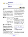
Figure 2 displays an overview of the communication between eZ80F91 web server and an HTML browser.
Figure 2. Communication Between Client Browser and the eZ80F91 Web Server
The web server transmits an HTML file (containing a link to the Java applet) to the client browser. The Java
applet contains a graphical user interface (GUI) component that is displayed on the web page as shown in
Figure 3 and Figure 4 on page 6. The web page displays the buttons that control the LEDs and the indicators
(LED icons) that are controlled by the switches on the Development Platform.
AN017806-0810
Page 5 of 22
A Web Page Interface for the eZ80F91 MCU Using Java
AN0178 Demo
Figure 3. LED and Switch Control Demo Web Page
Figure 4. Java Applet Component on HTML Web Page
Note: By default, the HTTP server closes the TCP connection as soon as the HTTP request is
processed, and, therefore, persistent connections are not possible.
AN017806-0810
Page 6 of 22
A Web Page Interface for the eZ80F91 MCU Using Java
The software implementation can be divided into the following sections:
•
•
Designing the web page, which includes coding the Java applet for the GUI.
Developing the functionality, which comprises the following:
– Implementing the functionality to control the LEDs on the Development Platform
– Implementing the functionality to effect a change in the indicators (LED icons) on the web page using
the switches on the Development Platform
Creating the Web Page
The source code of for the HTML file Switch.htm displays the web page as shown in Figure 3 on page 6. The
HTML script contains a link to the Java applet using the following lines of code:
<applet width="340" height="250" code="SwitchCtrl.class">
<param name="bgcolor" value="#FFFFFF">
</applet>
The applet is executed from the Java class file SwitchCtrl.class, which is previously stored in the
eZ80F91 web server in the form of ASCII characters. The SwitchCtrl.class file is obtained upon
compiling the SwitchCtrl.java file. The Java file SwitchCtrl.java is coded as detailed in this
application note. The entire Java source code is available in AN0178-SC01.zip.
Importing Relevant Java Packages
In the SwitchCtrl.java file, the relevant packages that the main program uses are imported in the
beginning of the file. The packages are similar to the *.lib and *.h files of the C language. In the program
for the applet, the following packages containing the relevant classes are defined as imported:
import
import
import
import
import
java.applet.Applet;
java.awt.*;
java.io.*;
java.net.*;
java.awt.event.*;
The imported packages are part of the core Java APIs that every Java program uses in the Java run-time
environment. The java.applet package contains classes that are essential for Java applets. The
java.awt package contains the most frequently used classes in the Abstract Window Toolkit (AWT), which
provides the Java graphical user interface (GUI) properties.
A subclass to extend the properties provided to the applet by the packages is implemented next, with the
following lines of code:
public class SwitchCtrl extends Applet implements Runnable ,
ActionListener{
...
)
The extends keyword indicates that SwitchCtrl is a subclass of the Applet class.
From the Applet class, applets inherit a great deal of functionality, the most important of which is the ability
to respond to browser requests. When a Java-capable browser loads a page containing an applet, the browser
AN017806-0810
Page 7 of 22
A Web Page Interface for the eZ80F91 MCU Using Java
sends a request to the applet telling the applet to initialize itself and start executing.
Declaring the Variables
After creating the Applet class, the variables that can be used by any function or subclass are declared within
the SwitchCtrl class as follows:
...
Socket rwSocket;
Socket inSocket;
Thread readThread;
String ipaddr=null;
String ip=null;
int portNumber;
int port;
Button xButton;
Button yButton;
DataOutputStream os;
DataInputStream is;
Image image1;
Color firstBulbColor = Color.green;
Color secondBulbColor = Color.green;
Initializing the Applet
The applet is initialized using the public void init() method. The init() method is called when the
applet is first created and loaded by the underlying software (the web browser). This method performs all the
one-time operations that the applet requires for its operation such as creating the user interface or setting the
font or displaying the logo.
...
public void init(){
...
}
The file formats *.gif and *.jpg are used to load and display images on the browser screen. Images are
stored as an instance of the Image class. The applet method getImage() returns an instance of these files:
image1 = getImage(getDocumentBase(), "logo.gif");
Setting the Applet Background Color
The following piece of code is used to set the background color of the applet based on the color value received
from the HTML page:
...
String s3 = getParameter("bgcolor");
if(s3 != null)
try{
setBackground(new Color(Integer.parseInt(s3.substring(1),16)));
}
...
The catch() method that is used to handle errors and exceptions in Java is used to handle invalid color
values. The error message is displayed on the Java Console that can be opened from the web browser.
AN017806-0810
Page 8 of 22
A Web Page Interface for the eZ80F91 MCU Using Java
Note: The Java Console is available as an option under the Tools menu in the web browser when the
Java Runtime Environment (JRE) is installed on the client PC. The JRE can be downloaded from
the website, http://www.java.sun.com.
...
catch(NumberFormatException _ex){
System.out.println("Invalid format for bgcolor: " + s3);
}
setLayout(null);
...
Creating the Buttons
To create buttons with text, the new Button() method is used. The setBounds() method specifies the
area (the X and Y axis) where the button is to be placed on the web page and also specifies its width and
height.
The add() method adds the new button to the Applet. The setEnabled() method either activates or
disables the button. The button is activated only when the setEnabled() method is true and disabled when
it is false. The following code illustrates the methods explained to create buttons:
...
xButton = new Button("D1");
xButton.setBounds(120, 160, 50, 30);
xButton.addActionListener(this);
add(xButton);
yButton = new Button("D2");
yButton.setBounds(180, 160, 50, 30);
yButton.addActionListener(this);
add(yButton);
xButton.setEnabled(true);
yButton.setEnabled(true);
...
Obtaining the Host IP Address
The applet is started using the public void start() method. The IP address of the host where the
applet is run must be obtained so that a socket can be opened for a communication channel to be set up
between the client and the web server. The following code is used to set the port number and obtain the host IP
address, which is then sent to the web server (see the “Adding and Integrating Application-Specific Files to
ZTP” section on page 14):
...
public void start(){
System.out.println("Enter Start");
ipaddr = getCodeBase().getHost();
System.out.println("IP Addr " + ipaddr.toString());
portNumber = 80;
System.out.println("PortNumber=" + portNumber);
AN017806-0810
Page 9 of 22
A Web Page Interface for the eZ80F91 MCU Using Java
The following code handles the error due to a connection failure:
try{
rwSocket = new Socket(ipaddr.toString(), portNumber);
}catch(UnknownHostException _ex){
System.out.println("An error occurred while establishing the communication
with the server");
}catch(IOException _ex){
System.out.println("Couldn't get I/O for the connection to: " +ipaddr);
}catch(Exception e){
System.out.println("An error occurred while reading the response.Try
reloading the page. ");
}
A new thread is then created and started with the following lines of code:
if(readThread == null){
readThread = new Thread(this);
readThread.start();
}
Creating the Applet Heading
The text or the heading for the Applet is printed using the paint(Graphics) method of the
java.awt.Graphics package. The paint(Graphics) method is coded as follows:
public void paint(Graphics g) {
System.out.println("Enter Graphics"+g);
g.setColor(Color.black);
g.fillRect(0,0,400,28);
g.drawImage(image1,0,0, this);
g.setColor(Color.white);
g.setFont(new Font("Arial", 1, 14));
g.drawString("LED and Switch Control Demo", 75, 18);
g.setColor(Color.yellow);
g.setFont(new Font("Arial", 1, 10));
g.drawString("Press the switches on the board to activate the
LEDs below", 40, 45);
g.setColor(Color.white);
g.setFont(new Font("Arial", 1, 10));
g.drawString("LED1", 139, 62);
g.drawString("LED2", 191, 62);
g.setColor(firstBulbColor);
g.fillOval(130,70,40,40);
g.setColor(secondBulbColor);
g.fillOval(185,70,40,40);
g.setColor(Color.yellow);
g.setFont(new Font("Arial", 1, 10));
g.drawString("To switch ON / OFF the LEDs on the board, click
the buttons", 25, 145);
System.out.println("Exit Graphics");
}
The setFont() method is used to set the font. The drawString() method prints the specified text on the
AN017806-0810
Page 10 of 22
A Web Page Interface for the eZ80F91 MCU Using Java
browser. The fillOval() method paints the LED icons (labeled as LED1 and LED2 on the web page) on
the screen according to the position (X and Y axis) and size (width and height) as specified. The
setColor() method is used to specify the color for the LED icon.
Synchronizing Independent Threads
To run the main thread and obtain the IP address of the client at Port 5000 (user specified), the following code
is used. The synchronized keyword tells the applet to synchronize all the threads.
synchronized public void run() {
System.out.println("Enter RUN");
ip = getCodeBase().getHost();
System.out.println("IP Addr " + ip.toString());
port = 5000;
Reading and Parsing the Data from the Port
When the applet runs, the browser displays the indicators (LED icons, LED1 and LED2) and buttons (SW1
and SW2) on the screen.
The Socket class is used to set up Port 5000 for input. The data on the port is then read and parsed to obtain
the proper string value after eliminating & and \n characters. This value is then passed to the
updateBulbStatus() method.
...
try{
inSocket = new Socket(ip.toString(),port);
is = new DataInputStream(inSocket.getInputStream());
System.out.println("InStream is:>> " +is);
while(true) {
str = "";
while((b = is.readByte()) != '&') { }
while ((b = is.readByte()) != '\n') {
str = str + (char)b; //read bytes, not Unicode characters
}
System.out.println("Input read is:>>" +str);
updateBulbStatus(str);
}
}catch(Exception e) {
System.out.println("An error occurred while reading the
response.Try reloading the page. ");
}
...
Changing the Color of the Indicators
The updateBulbStatus() method, which toggles the color of the indicators (LED icons) on the web page
between red and green, is constructed as follows:
public void updateBulbStatus(String msg){
System.out.println("Enter UpdateBulbStatus");
System.out.println("Received String" +msg);
if (msg.equals("LED1on")) {
redraw(1,Color.red);
}
AN017806-0810
Page 11 of 22
A Web Page Interface for the eZ80F91 MCU Using Java
else if (msg.equals("LED1off")){
redraw(1,Color.green);
}
else if (msg.equals("LED2on")){
redraw(2,Color.red);
}
else if (msg.equals("LED2off")){
redraw(2,Color.green);
}
System.out.println("Exit updateBulbStatus");
}
...
Controlling the LEDs on the Development Platform
When the button SW1 or SW2 is clicked on the web page, the actionPerformed() method is invoked,
and a data string corresponding to the clicked button is stored in variable s.
...
public void actionPerformed(ActionEvent ev) {
System.out.println("Enter Action Performed");
String label = ev.getActionCommand();
String s = new String();
if(label.equals("D1")){
s = "command=1&dummy=0";
sendData(s);
}else if(label.equals("D2")){
s = "command=2&dummy=0";
sendData(s);
}
System.out.println("Exit Action Performed");
}
The data in the string s is sent to the socket by the sendData() method with an alert for any error that may
occur. After sending the data, the socket is closed to complete the communication. The HTTP layer of the web
server listening on Port 5000 parses and interprets this data and provides the requisite value to the CGI
function switchinput_cgi.
...
public void sendData(String s) {
System.out.println("Enter SendData");
String s1 = null;
s1 =s;
s1 = "GET /switch_cgi?" + s1 + " HTTP/1.1\r\n";
s1 = s1 + "Host: " + ipaddr.toString() + "\r\n\r\n";
System.out.println("Data to send =" + s1);
try{
System.out.println("rwSocket::"+rwSocket);
Socket outSocket = new Socket(ipaddr, portNumber);
os = new DataOutputStream(outSocket.getOutputStream());
os.flush();
os.write(s1.getBytes());
outSocket.close();
}catch(IOException _ex){
AN017806-0810
Page 12 of 22
A Web Page Interface for the eZ80F91 MCU Using Java
System.err.println("Write exception"+_ex);
}
System.out.println("Exit Send Data");
}
The Java source code construction for the applet is now complete. To compile this code, the Java compiler
version 1.1 must be installed on the PC (PCs with a web browser such as Mozilla Firefox or Netscape already
contain the Java Virtual Machine that contains the Java compiler). The following command, at the DOS
prompt, is used to compile the Java code:
Javac –deprecation –target 1.1 SwitchCtrl.java
After successful compilation, a class file SwitchCtrl.class is created. This class file is further
converted to a SwitchCtrl_class.c file (where the contents of the file are stored in the form of an array)
when the project is compiled using the Zilog’s ZDS II compiler.
Controlling the LEDs on the Development Platform
In the Java-Based Web Page Interface application a CGI function, switchinput_cgi() is used to call the
ZTP HTTP CGI functions in order to read the user input from the HTML web page when the button SW1 or
SW2 is clicked on the web page, and to transmit that input data to the Development Platform. For more details,
see the “ZTP HTTP CGI Functions” section on page 4.
The switchinput_cgi() function is declared as follows:
INT16 switchinput_cgi(struct http_request *request)
This CGI function initially calls the ZTP HTTP API http_init() function to initialize the web server,
makes a TCP connection on the specified port and waits for a client request. On receiving a request from the
client, the web server provides a response according to the web server configuration.
The CGI function then calls the ZTP HTTP CGI function, http_output_reply() to send an
acknowledgement to the client browser. The http_find_argument() is called to search for the string
command indicating which of the buttons (SW1 or SW2) is pressed; the respective LED on the Development
Platform is then switched ON/OFF. Figure 5 on page 20 shows the sequence of events.
Controlling the LED Icons on the Web Page
The Port B of the eZ80F91 MCU is initialized with PB0 and PB1 as input pins and PB3 and PB4 as output
pins (see the Switch.c file in the AN0178-SC01.zip file available on the Zilog web site). Port B is
continuously polled for any change in status in ZTP’s main.c file.
When the SW1/SW2 switch on the Development Platform is pressed, the change in the switch status is
captured by the Switch_Input() function (a flag is set or reset to indicate the status of the switches) and
an appropriate string is written for the switch. The strings LEDon or LEDoff are used to indicate whether the
LED icons on the web page must be displayed in green (OFF) or red (ON). These strings are sent as arguments
in the switchinput_cgi() function. See the “Controlling the LEDs on the Development Platform”
section on page 12 for details of this CGI function.
The ZTP HTTP API http_find_argument() is called within the switchinput_cgi() function to
AN017806-0810
Page 13 of 22
A Web Page Interface for the eZ80F91 MCU Using Java
search for the string (LED1on/LED1off). This string is sent to the browser where the color of the indicators
(LED icons, LED1/LED2) on the web page turns green or red. Figure 6 on page 21 shows the sequence of
events.
Adding and Integrating Application-Specific Files to ZTP
The Java-Based Web Page Interface applic ation described in this application note requires the eZ80®
Development Platform with the eZ80F91 module, and the Zilog TCP/IP stack (ZTP). To execute this
application, the files specific to the application must be added and integrated to the ZTP stack before the stack
is downloaded onto the eZ80F91 MCU. This section contains the details of adding the application specific files
to the ZTP stack.
The Java-Based Web Page Interface files are in the AN0178-SC01.zip file available on the Zilog web site.
The application files are of the following types:
•
•
•
•
•
C (*.c) files
Header (*.h) files
HTML (*.htm/*.html) files
Java (*.class) files
Image (*.gif) files
The ZTP stack is available on the Zilog website and can be downloaded to a PC with a user registration key.
ZTP can be installed in any location as specified by the user; its default location is C:\Program
Files\ZiLOG.
Note: Before adding and integrating the application specific files to ZTP, ensure that all the settings
for the ZTP stack are at default values.
Perform the following steps to add and integrate the Demo files to the ZTP stack:
1.
2.
Download ZDS II Acclaim 5.0.0 with ZTP 2.3.0 and install, browse to the location where ZTP was
installed and open the following directories:
...\ZTP\ZTP2.3.0_Lib\ZTP\SamplePrograms\ZTPDemo
...\ZTP\ZTP2.3.0_Lib\ZTP\SamplePrograms\Website.Acclaim
Download AN0178-SC01.zip and extract its contents to a directory on your PC. There are two
extracted folders within AN0178-SC01:
\JWC_Demo
\JWC_website.acclaim
3.
4.
Select and copy all the *.htm (or *.html), *.gif files, and *.class files located in the
\JCW_website.acclaim directory to the
...\ZTP\ZTP2.3.0_Lib\ZTP\SamplePrograms\Website.Acclaim directory. Copy the
*.c and *.h files located in the \JCW_Demo directory to the
...\ZTP\ZTP2.3.0_Lib\ZTP\SamplePrograms\ZTPDemo directory.
Launch ZDS II–eZ80Acclaim! 5.0.0 and open the website.zdsproj project located in the
...\ZTP\ZTP2.3.0_LIB\ZTP\SamplePrograms\Website.Acclaim directory.
a) Add all the *.htm (or *.html) and *.class and *.gif files located in the
...\ZTP\ZTP2.3.0_LIB\ZTP\SamplePrograms\Website.Acclaim directory to the
website.zdsproj project. To do so, click Project and then click Add Files.
AN017806-0810
Page 14 of 22
A Web Page Interface for the eZ80F91 MCU Using Java
b)
• The *.htm file to be added is: switch.htm
• The *.class file to be added is: SwitchCtrl.class
• The *.gif file to be added is: Logo.gif
Open the website.c file from within ZDS II and add the following prototype declarations to it:
// Java-Based Web Page Interface Demo pages
extern const struct staticpage switch_htm;
// Java Applets
extern const struct staticpage SwitchCtrl_class;
// CGI functions
extern int switchinput_cgi (struct http_request *request);
// Pictures: JPG, GIF
extern const struct staticpage logo_gif;
c) The website.c file contains an array, Webpage website [ ], that provides information
about the HTML pages. Replace the last line of the array {0, NULL, NULL, NULL} with the
following lines of code:
{HTTP_PAGE_STATIC, "/SwitchCtrl.class", "application/ octect-stream",
&SwitchCtrl_class},
{HTTP_PAGE_STATIC, "/switch.htm", "text/html", &switch_htm},
{HTTP_PAGE_DYNAMIC, "/switch_cgi", "text/html", (struct staticpage *)
&switchinput_cgi},
{HTTP_PAGE_STATIC, "/logo.gif", "image/gif", &logo_gif},
{0, NULL, NULL, NULL}
d) From within ZDS II–Acclaim 5.0.0, open the left.htm file located in the \Web Files
directory. Search for the Demos<br> statement and add the following piece of HTML code
above the Demos<br> statement to create a link from the default eZ80Acclaim! ® web page to
the Java Switch Applet web page:
Java Demo<br>
<a href="switch.htm">AN0178 Demo</a><br> <br>
e) Build the website.zdsproj project to obtain the new library file
Acclaim_website.lib.
f) Copy this Acclaim_website.lib from the
...\ZTP\ZTP2.3.0_LIB\ZTP\SamplePrograms\Website.Acclaim directory to
the ...\ZTP\ZTP2.3.0_LIB\ZTP\Lib directory where it will replace the existing one.
Note:
The
...ZTP\ZTP2.3.0_Lib\ZTP\Lib
folder
already
contains
an
Acclaim_website.lib file, and it must be replaced with the newly generated file. Click Yes
to replace the file.
5.
g) Close the website.zdsproj project.
From within ZDS II, open the ZTPDemo_F91.zdsproj file available in the
...\ZTP\ZTP2.3.0_LIB\ZTP\SamplePrograms\ZTPDemo directory.
a) Add the *.c file located in the
...\ZTP\ZTP2.3.0_LIB\ZTP\SamplePrograms\ZTPDemo directory to the
ZTPDemo_F91.zdsproj project. To do so, click Project and then click Add Files.
The *.c file to be added is: switch.c
b) For this application, DHCP (Dynamic Host Configuration Protocol) is disabled; therefore, ensure
that the following is set in the ZTPConfig.c file:
UINT8 b_use_dhcp = FALSE;
AN017806-0810
Page 15 of 22
A Web Page Interface for the eZ80F91 MCU Using Java
c) Look for the following structure definition in the ZTPConfig.c file:
struct commonServers
"172.16.6.48",
"",
"",
"",
"172.16.6.194"
};
csTbl={
/* Default
/* Default
/* Default
/* Default
/* Default
Timer Server */
Network Timer Server( NTP ) */
rfs server */
File Server - Not currently Used */
Name Server */
struct If ifTbl[MAX_NO_IF]= { /*interface 0 -> Ethernet Configurattion*/
{
&usrDevBlk[0],
/* Control block for this device*/
ETH,
/* interface type */
ETH_MTU,
/* MTU */
ETH_100,
/* Speed ETH_100, ETH_10, ETH_AUTOSENSE */
"172.16.6.203",
/* Default IP address */
"172.16.6.1",
/* Default Gateway */
0xffffff00UL
/* Default Subnet Mask */
},
Note: The Bootrecord variable contains network parameters and settings (in the four-octet
dotted decimal format) specific to the local area network at Zilog, by default. Modify the above
structure definition with appropriate IP addresses within your local area network (For details
about modifying the structure definition, refer to the ZTP 2.3.0 documents.)
d) Open the emac_conf.c file and change the default MAC address (provided by ZTP) such that
each eZ80® Development Platform on the LAN contains a unique MAC address. For example,
INT8 f91_mac_addr[ETHPKT_ALEN] = {0x00,0x90,0x23,0x00,0x04,0x04};
In the 6-byte MAC address shown above, the first three bytes must not be modified; the last three
bytes can be used to assign a unique MAC address to the eZ80Acclaim! ® Development Platform.
e) Open the main.c file of the ZTPDemo_F91.zdsproj project and add the following given
include file :
#include "switch.h"
Add the following line:
RZK_THREADHANDLE_t g_hdl_T1;
f) Add the following lines of code above the return(OK) statement located at the end of the
ZTPAppEntry function in main.c file:
PortBInit();
g_hdl_T1 = RZKCreateThreadEnhanced((RZK_NAME_t *)"THREAD1",
(RZK_PTR_t)AcceptClient,
NULL,
T1_STACK,
T1_PRIO,
T1_TICKS,
RZK_THREAD_PREEMPTION | RZK_THREAD_ROUNDROBIN,0);
if (g_hdl_T1 == NULL)
xc_fprintf(CONSOLE,"Can't create the thread (INVALID handle)");
else
RZKResumeThread(g_hdl_T1);
AN017806-0810
Page 16 of 22
A Web Page Interface for the eZ80F91 MCU Using Java
6.
g) Comment out the following line in the main.c file:
Initialize_FileSystem(); ? //Initialize_FileSystem();
Also comment the Intialize_Filesystem() function description in the main.c file
h) In the ZTPInit_Conf.c file, comment out the following line:
Init_DataPersistence(); ? //Init_DataPersistence();
i) In the ZTPConfig.c file, make the following change:
g_ShellLoginReqd = FALSE
Save the files and close the ZTPDemo_F91.zdsproj project.
Demonstration
This section contains the requirements and instructions to set up the Java-Based Web Page Interface Demo and
run it.
Requirements
There are hardware and software requirements.
Hardware
• eZ80F91 Development Kit
• eZ80Accla imPlus!-based evaluation board
• PC with an Internet browser (Mozilla Firefox) with the Java Virtual Machine.
Software
• Zilog Developer Studio II—IDE for eZ80Acclaim! 5.0.0 (ZDS II 5.0.0)
• Zilog’s TCP/IP stack (ZTP 2.3.0)
Setup
The basic setup to assemble the Java-Based Web Page Interface demo is illustrated in Figure 1 on page 3. This
setup illustrates the connections between the PC, Smart Cable, LAN/WAN/Internet and the eZ80F91
Development Kit.
Settings
HyperTerminal Settings
Set the HyperTerminal to 57.6 Kbps Baud and 8-N-1 with no flow control.
Additional Settings for the eZ80® Development Platform
• Connect PB3 of J6 Header to Pin6 of the J9 Connector (Count Pin6 starting from the J9 marking). Or
connect an LED to PB3 of J6 Header with respect to ground.
• Connect PB4 of J6 Header to Pin7 of the J9 connector (Count Pin7 starting from the J9 marking). Or
connect an LED to PB4 of J6 Header with respect to ground
Procedure for Setting up the Java-Based Web Page Interface Demo
The procedure to build and run the Java-Based Web Page Interface Demo is described in this section.
1.
2.
Ensure that the required Java-Based Web Page Interface Demo files are added and integrated to ZTP
before proceeding. See the “Adding and Integrating Application-Specific Files to ZTP” section on
page 14.
Make the connections as shown in Figure 1 on page 3. Connect the power supply of the eZ80F91
Development Kit.
AN017806-0810
Page 17 of 22
A Web Page Interface for the eZ80F91 MCU Using Java
3.
4.
5.
6.
7.
Connect the eZ80 development platform to the PC with a crossover Ethernet cable. This connection is
made by means of the orange-colored cable. This Ethernet connection can also be made via a hub or
switch.
Launch ZDS II for eZ80Acclaim! and open the Java-Based Web Page Interface Demo project file
(ZTPDemo_F91.zdsproj) located in the
...\ZTP\ZTP2.3.0_LIB\ZTP\SamplePrograms\ZTPDemo directory.
Build the project and download the resulting file ZTPDemo_F91_FLASH.hex file (located in the
...\ ZTP\ZTP2.3.0_LIB\ZTP\SamplePrograms\ZTPDemo directory) into an eZ80F91
module that is attached to the eZ80 development platform. Push the Reset button on the platform.
After reset, the eZ80 development platform is ready to work as a web server gateway. The
programming is performed using Zilog’s ZDS II Flash Loader utility (Tools > Flash Loader).
Connect either the port marked CONSOLE with a straight-through cable to a PC port used by a
terminal program such as HyperTerminal.
Once IP assigned to the gateway is known, user can use the IP address in the Mozilla Firefox and run
the Web Page Interface for the eZ80F91 MCU Using Java application Demo. Refer to the next section.
Running the Running the Java-Based Web Page Interface Demo
Use the following procedure to run the Java-Based Web Page Interface Demo:
1.
Launch the Internet browser on the PC. Enter the IP address for the eZ80® Development Platform
specifie d in ZTPConfig.c. The Index.html page is displayed. The LEDs (labeled DCD and RX)
on the Development Platform light up to indicate an active link between the eZ80F91 web server and
the PC-based client browser.
2.
Click on the Switch link under Java Switch Demo located in the left side of the screen. A new web
page (LED and Switch Control Demo) opens displaying the buttons and the indicators (LED icons).
3.
Click on the SW1 button on the Switch Control Demo Website. Notice that the LED (labeled DCD) on
the Development Platform is switched off and this on/off feature toggles on every mouse click. The
same procedure is performed on the SW2 button for the LED (labeled RX).
4.
Press the SW1/SW2 switch on the eZ80® Development Platform. The color of the indicator (LED
icons) changes from red to green. Subsequent clicking of the switches toggles the color of the LED
icons on the web page.
Summary
The eZ80F91 microcontroller is used for building Internet-enabled products that are controlled over an Internet
or intranet using web pages. This Application note demonstrates how the current status of a pin on the
eZ80F91 MCU can be remotely viewed and controlled by using a Java applet in a web page. This type of
simple interface utilizes the HTTP component of Zilog’s ZTP stack, which provides reliable transfer and
control of data. The details provided in this application note can be used to build more complex user interfaces
for real-world applications.
References
The following documents are associated with the eZ80®, eZ80Acclaim! ® , and eZ80AcclaimPlus!™ family of
products:
•
•
•
•
eZ80F91 Product Specification (PS0192)
Zilog TCP/IP Software Suite Programmer’s Guide Reference Manual (RM0008)
Zilog Developer Studio II—eZ80Acclaim! User Manual (UM0144)
eZ80AcclaimPlus!™ Connectivity ASSP eZ80F91 ASSP Product Specification (PS0270)
AN017806-0810
Page 18 of 22
A Web Page Interface for the eZ80F91 MCU Using Java
•
•
•
eZ80AcclaimPlus!™ ASSP Product Brief (PB0220)
eZ80F91 Mini Enet Module for eZ80AcclaimPlus!™ Product Specification (PS0271)
Zdots SBC for eZ80AcclaimPlus!™ Connectivity ASSP Product Specification (PS0261)
AN017806-0810
Page 19 of 22
A Web Page Interface for the eZ80F91 MCU Using Java
Appendix A—Flowcharts
This appendix contains the flowcharts for the Java-Based Web Page Control Interface implementation using
the eZ80F91 MCU.
Figure 5 displays the flowchart for toggling the LEDs on the eZ80® Development Platform using the D1 and
D2 buttons on the web page.
Figure 5. Flowchart to Toggle the LEDs on Development Platform Using Buttons
AN017806-0810
Page 20 of 22
A Web Page Interface for the eZ80F91 MCU Using Java
Figure 6 displays the flowchart for changing the color of the LED icons (LED1 and LED2) on the web page
using the SW1 and SW2 switches on the eZ80® Development Platform.
Figure 6. Flowchart to Change the Color of LED Icons on Web Page Using Switches
AN017806-0810
Page 21 of 22
A Web Page Interface for the eZ80F91 MCU Using Java
Warning:
DO NOT USE IN LIFE SUPPORT
LIFE SUPPORT POLICY
ZILOG'S PRODUCTS ARE NOT AUTHORIZED FOR USE AS CRITICAL COMPONENTS IN LIFE
SUPPORT DEVICES OR SYSTEMS WITHOUT THE EXPRESS PRIOR WRITTEN APPROVAL OF THE
PRESIDENT AND GENERAL COUNSEL OF ZILOG CORPORATION.
As used herein
Life support devices or systems are devices which (a) are intended for surgic al implant into the body, or (b)
support or sustain life and whose failure to perform when properly used in accordance with instructions for use
provided in the labeling can be reasonably expected to result in a significant injury to the user. A critical
component is any component in a life support device or system whose failure to perform can be reasonably
expected to cause the failure of the life support device or system or to affect its safety or effectiveness.
Document Disclaimer
©2010 by Zilog, Inc. All rights reserved. Information in this publication concerning the devices, applications,
or technology described is intended to suggest possible uses and may be superseded. ZILOG, INC. DOES
NOT ASSUME LIABILITY FOR OR PROVIDE A REPRESENTATION OF ACCURACY OF THE
INFORMATION, DEVICES, OR TECHNOLOGY DESCRIBED IN THIS DOCUMENT. ZILOG ALSO
DOES NOT ASSUME LIABILITY FOR INTELLECTUAL PROPERTY INFRINGEMENT RELATED IN
ANY MANNER TO USE OF INFORMATION, DEVICES, OR TECHNOLOGY DESCRIBED HEREIN OR
OTHERWISE. The information contained within this document has been verified according to the general
principles of electrical and mechanical engineering.
eZ80AcclaimPlus! is a trademark of Zilog, Inc. eZ80Acclaim! and eZ80 are registered trademarks of Zilog,
Inc. All other product or service names are the property of their respective owners.
AN017806-0810
Page 22 of 22