1
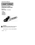
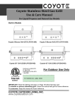
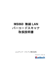
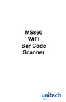
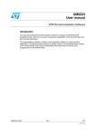
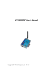
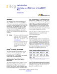
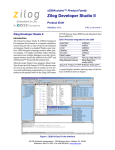
Wireless Zdots® Single Board Computer Development Kit Quick Start Guide QS007504-0410 Introduction This Quick Start Guide provides instructions to use Zilog’s Wireless Zdots® Single Board Computer (SBC) with the Demo project WLANDemo.zdsproj. WLANDemo.zdsproj is a sample project in which the communication of a PC to a web page is wireless, it is run by Zdots SBC. The WLANDemo.zdsproj is used along with standard Zilog TCP/IP (ZTP) software suite. This Demo project can only be used on Wireless Zdots SBC. Do not use this Demo project on Zilog’s eZ80Acclaim!® development kit. This project can also be used as the starting point for your application development. Figure 1. Wireless Zdots® SBC Development Kit Copyright ©2010 by Zilog®, Inc. All rights reserved. www.zilog.com Wireless Zdots® Single Board Computer Development Kit Wireless Module RS-232 Adapter Prototype Area ZDI Interface Wireless Development kit Base Board Figure 2. Wireless Zdots® SBC and Base Board NOR Flash eZ80F91 On-Board Antenna SRAM RS-232/PWR Input/Output MII Input/Output Figure 3. Wireless Zdots® SBC QS007504-0410 Page 2 of 19 Wireless Zdots® Single Board Computer Development Kit Wireless module Plug-in Headers Test Points DC Power Input ZDI Prototype Figure 4. Wireless Base Board Kit Contents This section describes the hardware and software requirements for installing and using Wireless Zdots® Single Board Computer Development Kit. Hardware The hardware included in this kit are: • eZ80AcclaimPlus! Wireless Zdots SBC • eZ80AcclaimPlus! Wireless Zdots SBC Development Kit Base Board • RS-232 Adapter • USB Smart Cable • 5 V DC Power Supply • RS-232 Cable QS007504-0410 Page 3 of 19 Wireless Zdots® Single Board Computer Development Kit Notes: The additional hardware that are required to run the Demo (not included in the kit) are: 1. A USB to Serial Adapter for host PC that do not have a serial COM port. 2. Wireless LAN router. Software and Documentation (on CD-ROM) The software included in this kit are: • Zilog Developer Studio II (ZDS II)-eZ80 Acclaim!® • Zilog TCP/IP Stack (ZTP) ZDS - Object Code Notes: 1. For latest revision, visit www.zilog.com. 2. For procedure to download the ZTP software, see Downloading the ZTP Software on page 18. System Requirements Table 1 lists the system requirements for running ZDS II. Table 1. ZDS II System Requirements Recommended Configuration Minimum Configuration PC running Microsoft Windows XP PC running Microsoft Windows XP Professional/ Professional Windows 2000 SP4/Windows 98 SE Pentium III/500 MHz or higher processor Pentium II/233 MHz processor 128 MB RAM 96 MB RAM 110 MB hard disk space 25 MB hard disk space (documentation not installed) Super VGA video adapter Super VGA video adapter CD-ROM drive CD-ROM drive One or more RS-232 communications ports One or more RS-232 communications ports USB high-speed port USB high-speed port QS007504-0410 Page 4 of 19 Wireless Zdots® Single Board Computer Development Kit Installing the ZDSII Software and Kit Documentation Follow the steps below to install the ZDS II and documentation: 1. Insert the ZDS II CD into the CD-ROM drive. DemoShield launches automatically. If the DemoShield does not launch automatically, open the Windows Explorer, browse to your CD-ROM drive, and double-click launch.exe to launch the installer. 2. From the product installer list you can choose to install ZDS II alone, or both ZDS II and associated documentation. You can also copy the documentation directly from your CD-ROM drive to your hard disk using Windows Explorer or read the documentation directly from the CD-ROM itself. For customer service and technical support, Zilog® recommends you to create an account on http://support.zilog.com. Installing the USB Smart Cable Follow the steps below for installing the USB Smart Cable and associated driver software. Windows Vista-32 Follow the steps below to install the USB Smart Cable for Windows Vista-32. 1. Connect the USB Smart Cable to the Host PC. The Found New Hardware dialog box is displayed. 2. Select Locate and install the driver software (recommended). The Driver Software Installation window is displayed, and then the Found New Hardware-USB Smart Cable dialog box is displayed. 3. Select I don’t have the disc. Show me other options. 4. Select Browse my computer for driver software (advanced). 5. Browse to the following driver directory: <ZDS II Installation Directory>\device drivers\USB The Windows Security dialog box is displayed. 6. Select Install this driver software anyway. 7. When the software is installed, click Closed. QS007504-0410 Page 5 of 19 Wireless Zdots® Single Board Computer Development Kit Windows XP Follow the steps below to install the USB Smart Cable for Windows XP: 1. Connect the Zilog USB device to the Host PC. The Found New Hardware Wizard should activate automatically after connecting the Zilog USB device for the first time; select No, not at this time if asked to connect to Windows Update. 2. Select Install from a list or specific location (Advanced); then click Next. Note: If the Windows Logo testing dialog appears, select Continue Anyway. 3. Select Search for the best driver in these locations and Include this location in search:. 4. Browse to the following driver directory and click Next. <ZDS installation>\device drivers\USB\ 5. Click Next after the appropriate driver is found. 6. Click Finish to complete the installation. Windows 2000 Follow the steps below to install the USB Smart Cable for Windows 2000: 1. Connect the Zilog USB device to the Host PC. The Found New Hardware Wizard should activate automatically after connecting the Zilog USB device for the first time. 2. Click Next in the Found New Hardware Wizard after it has been activated. 3. Select Search for a suitable driver for my device (Recommended) and click Next. 4. Select Specify a location and click Next. 5. Browse to the following driver directory and click OK. <ZDS installation>\device drivers\USB\ 6. Click Next after the appropriate driver is found. 7. Click Finish to complete the installation. QS007504-0410 Page 6 of 19 Wireless Zdots® Single Board Computer Development Kit Windows 98SE Follow the steps below to install the USB Smart Cable for Windows 98SE: 1. Connect the Zilog USB device to the Host PC. The Add New Hardware Wizard should activate automatically after connecting the Zilog USB device for the first time. 2. Click Next in the Add New Hardware Wizard after it has been activated. 3. Select Search for the best driver for your device (Recommended) and click Next. 4. Select Specify a location: and browse to the following driver directory, and click Next. <ZDS installation>\device drivers\USB\ 5. Click Next after the appropriate driver is found. 6. Click Finish to complete the installation. Hardware Setup Figure 5 displays the hardware setup for the ZTP Wireless Local Area Network (WLAN) Demo application that is used to demonstrate wireless data transfer. Figure 5. Hardware Setup for the ZTP WLAN Demo Application QS007504-0410 Page 7 of 19 Wireless Zdots® Single Board Computer Development Kit RS-232 Driver 6 Pin TTL Level TX, RX, RTS, CTS, 3.3 V and Ground RS-232 DB9 Figure 6. RS-232 Adapter Follow the steps below to set up the hardware: 1. Connect Zdots SBC to J1 of the Wireless base board. See Figure 2 on page 2 for actual image. The SBC must be connected before applying the power. Note: Pin 1 of Zdots SBC should match the pin 1 of the base board; this is indicated by square solder around the pin. 2. Connect the RS-232 adapter (99C1067-001G) to the WLAN Zdots SBC J3 header. Note: Pin 1 is indicated by the square solder on the solder side. 3. Connect the USB Smart cable (or any Zilog Debug tool) to the 6-pins ZDI interface on the Wireless Base Board on your development PC. See Connecting the USB Smart Cable to the Development Board on page 9. 4. Connect the RS-232 cable to the RS-232 adapter P1 connector and the other end to the communication port (COM1) of the PC. Note: This is connected on your PC as displayed in Figure 5 on page 7. 5. Connect the power supply (5 V DC) cable to the Wireless Base board J4 connector. 6. Set up an access point (AP) in the test area and power it ON. For information on how to set up the wireless router, see Configuring the Router on page 15. QS007504-0410 Page 8 of 19 Wireless Zdots® Single Board Computer Development Kit Connecting the USB Smart Cable to the Development Board Caution: The power to the development board must be disconnected or turned OFF before connecting or disconnecting the USB Smart Cable. Attach one end of the six-conductor ribbon cable (included) to the USB Smart Cable sixpin DBG connector (see Figure 7). Attach the free end of the ribbon cable to the DBG connector (ZDI Interface) on the development board. Ensure that pin 1 on the ribbon cable (indicated by the dark stripe) is aligned with pin 1 on the target connector (indicated by a square solder on the DBG pin). Figure 7. Connecting the Six-Conductor Ribbon Cable to the USB Smart Cable Configuring the HyperTerminal Application The HyperTerminal program must be configured before starting the Demo application. Follow the steps below to configure the HyperTerminal application: 1. In Windows operating system, launch the HyperTerminal application by navigating to Start All Programs Accessories Communications HyperTerminal. The Connection Description dialog box is displayed. 2. Enter the name for a new connection in the Connection Description dialog, and click OK. The Connect To dialog box is displayed. 3. In the Connect Using text field, select the port (COM1 or COM2) to which the serial cable is connected. Click OK to open the Port Settings dialog box for the selected port. QS007504-0410 Page 9 of 19 Wireless Zdots® Single Board Computer Development Kit 4. In the Port Settings tab of dialog box, enter the following values in the respective text fields: Bits per second 57600 bps Data bits 8 Parity None Stop Bits 1 Flow control None 5. Click OK to establish connection to the eZ80® development platform using the serial port. How to Execute WLAN Demo Application Running the RAM-Based WLAN Demo Project using the ZDS II Toolset Follow the steps below to execute the WLAN Demo project in the Zilog Developer Studio II (ZDS II) development environment: Note: The following procedures reference the WLANDemo.zdsproj located in the CD-ROM. Insert Zilog TCP/IP Stack (ZTP) ZDS - Object Code Version X.Y.Z1 CD into the CD-ROM drive. InstallShield Wizard appears and starts installation. Follow the on-screen procedures. By default, it is installed at C:\Program Files\ZiLOG\ZTP_X.Y.Z_Lib_ZDS. 1. Set up the hardware as displayed in Figure 5 on page 7. 2. To launch ZDS II, navigate to Start All Programs Zilog ZDS IIeZ80Acclaim!_<Version> _ZDS II-eZ80Acclaim!_<Version>. 3. Select Open Project from the File menu in ZDS II to open the sample ZTP Demo project located in the following path: For ZDSII - eZ80Acclaim! 5.1.0: C:\Program Files\ZiLOG\ZDSII_eZ80Acclaim!_5.1.0\ZTP\ZTP2.3.1_Lib\ZTP\ SamplePrograms\WLANDemo\WLANDemo.zdsproj 1 Where X.Y.Z refers to the major, minor, and revision number of the release. QS007504-0410 Page 10 of 19 Wireless Zdots® Single Board Computer Development Kit <ZTP Installed Dir>\ZTP_X.Y.Z_Lib_ZDS\ZTP\SamplePrograms\WLANDemo\WLANDemo.zdsproj> where <ZTP Installed Dir> is the path to the ZTP folder that you set when you installed the ZTP_X.Y.Z_Lib_ZDS. The default location of <ZTP Installed Dir> is C:\Program Files\ZiLOG. 4. Select Build Set Active Configuration to open the Select Configuration dialog box, and select the RAM configuration. 5. From the Project menu in ZDS II, select Settings. The Project Settings dialog box appears. 6. In the Project Settings dialog box, select the Debugger tab. In the Debugger tab, ensure eZ80F91_WiFi_RAM option is checked and the correct debug tool is selected. In this Demo, USB Smart Cable is used as the Debug Tool. 7. Click OK to close the Project Settings dialog box. Note: If the ZDS II prompts to Rebuild the Project, click YES to enable the configuration on Project Settings. 8. After the successful build, run the Demo application using Debug Go. This is observed on Hyper Terminal window: Initializing SPI Initializing SDIO card get SYSCLKR=c0000000 set SYSCLKR=c0000003 get SYSCLKR=c0000003 RTL8711_3rdCUT SYSCTRL : 68 ! EEPROM ID=8711 EEPROM MAC Address = 0-90-23-0-4e-ab Downloading FW# totlen=118300, img sz=118200, hdrsz=100...Done Firmware Init OK[ZTP ]> 9. Once the shell prompt appears, use the scan command on the Hyper Terminal window and press Enter to search the access points (AP) available in the range. QS007504-0410 Page 11 of 19 Wireless Zdots® Single Board Computer Development Kit Firmware Init OK[ZTP ]>scan SSID Scanning .................Done Number of Aps 2 SSID MAC Address Ch ================== ================= == 00:20:a6:50:f3:65 11 NETGEAR 00:18:f8:4a:62:48 11 [ZTP ]> RSSI ==== ffa2 ffa2 Secure ===== WEP WEP Then use the wep [<SSID> <keyld=0-3> [keyDataHex]]shell command to specify the hexadecimal WEP key. To display the current WEP key information just issue the ‘wep’ command with no parameters. Use the join<SSID> shell command to connect to a specified AP. [ZTP ]>wep NETGEAR 0 378E919303657C6DBCA9B29A5E Active WEP key for SSID NETGEAR is 0 37 8e 91 93 03 65 7c 6d bc a9 b2 9a 5e [ZTP ]>wep Active WEP key for SSID NETGEAR is 0 37 8e 91 93 03 65 7c 6d bc a9 b2 9a 5e [ZTP ]>join NETGEAR Sending Auth.... Joining BSS....SSID NETGEAR Querying DHCP Server...DHCP OK Initializing network stack... IF IP addr Def Gtway state 0 10.20.2.39 10.20.2.39 UP type Ethernet HTTPD ready TELNET ready[ZTP ]> For more details on shell commands, refer to Zilog TCP/IP Software Suite Programmer’s Guide (RM0041). Note: SSID and WEPKEY are provided by the wireless router. In this demo NETGEAR and 378E919303657C6DBCA9B29A5E key are used. See Figure 9 and Figure 10 on page 17. 10. After successful connection to the BSS (AP) the network stack will be initialized and Zdots® SBC behaves as a complete wireless station. QS007504-0410 Page 12 of 19 Wireless Zdots® Single Board Computer Development Kit 1. To support FLASH and COPY_TO_RAM configuration on Wireless Zdots SBC (due to new external SPANSION Flash) ZDS II Flash driver configuration file must be modified. Replace the FlashDevice.xml file in the ...\ZDSII_eZ80Acclaim!_4.x.x\config folder with the file given in the WLANDemo folder. In the Project Settings Debugger; eZ80F91_WiFi_Flash must be selected for FLASH and COPY_TO_RAM configurations. After replacing the FlashDevice.xml file close all ZDS II instances and reopen again. Notes: 2. By default the wlan_conf.c file contains WLAN parameters set to zero. In this case, you can configure these parameters through shell and connect to a BSS (AP). 3. If the WLAN parameters in wlan_conf.c are valid (that is, not initialized to NULL), the Demo connects to the specified BSS (AP) without the user interaction. 4. In FLASH and COPY_TO_RAM configurations the SSID and WEP key can be set through the configwlan shell command. For more details, refer to Zilog TCP/IP Software Suite Programmer’s Guide (RM0041). 5. The Zdots® WLAN solution cannot be configured to work as an Access Point. Web Server Demonstration Follow the steps below to use the features of WLAN Demo: 1. When you run the WLAN Demo application Zdots SBC accesses the BSS with the specified SSID and displays the network parameters such as IP address and a login prompt on the HyperTerminal. You can type help on the prompt to know other command line applications. 2. Use ping command from any PC in the same BSS/ESS as Zdots SBC running ZTP. Ping command can be used from Zdots SBC shell to other PC also. 3. Open an Internet Explorer from a PC/laptop where the router is connected and browse the eZ80® WLAN Zdots SBC with the IP specified on the Hyper Terminal. In this demo the given IP address is 192.168.1.102. See Figure 8. Note: IP Address may vary. Please verify this value on IP addr on the hyperterminal. QS007504-0410 Page 13 of 19 Wireless Zdots® Single Board Computer Development Kit Figure 8. Website Browsing You can use Telnet client from a PC to browse the eZ80 WLAN Zdots SBC and access its shell prompt through the wireless connection. QS007504-0410 Page 14 of 19 Wireless Zdots® Single Board Computer Development Kit Configuring the Router The following steps below in configuring the router is set with SSID equal to ‘NETGEAR’ and the generated keys: Note: These steps are based on LINKSYS WRT54G Router. 1. Disable the wireless connection on your laptop/PC. 2. If you are using Proxy server for your LAN settings, you can disable it by browsing to Start Settings Control Panel Internet Options Connections LAN Settings. Uncheck the proxy server on Proxy Server section then select Automatically detect settings on Automatic configuration section. Then click OK on LAN Settings and Internet Properties. 3. Connect the cable on the Ethernet port of your laptop/PC to the router (AP) using one of its port (not the internet port). 4. Power ON your router. 5. Type 192.168.1.1 in the address bar of Internet Explorer (IE). 6. Enter ‘admin’ in the Password field. Do not enter any User name. You can now see the Linksys page as displayed in Figure 9. 7. Select Wireless Basic Wireless Settings. Change the Wireless Network Name (SSID): field to ‘NETGEAR’. See Figure 9. QS007504-0410 Page 15 of 19 Wireless Zdots® Single Board Computer Development Kit Figure 9. Basic Wireless Settings 8. Click Save Settings. Then click Continue if settings are successful. 9. Select Wireless Wireless Security. Ensure that WEP is selected on the Security Mode: field as displayed in Figure 10 (Change the Security Mode to WEP through the drop down button). Note: Click Generate if Key 1 and other Keys do not have a value. QS007504-0410 Page 16 of 19 Wireless Zdots® Single Board Computer Development Kit Figure 10. Wireless Security 10. Click Save Settings. Then click Continue if settings are successful. 11. You can now try to connect using the specified SSID and Key 1. 12. You can now run your project. See: “How to Execute WLAN Demo Application” QS007504-0410 Page 17 of 19 Wireless Zdots® Single Board Computer Development Kit Downloading the ZTP Software Follow the steps below to download the ZTP software from Zilog website www.zilog.com: 1. Visit the link http://support.zilog.com/support/product/products.asp. 2. Login with registered username and password. After a successful login you can now register your product. Click on Register New Products, and enter the Registration Key Number found on the Registration Card that is included on the kit. Then click on the Register button. 3. Locate and find eZ80F91WF01ZCOG and click on the corresponding Updates Available link. 4. Click on Zilog TCP/IP Stack (ZTP) ZDS - Object Code to download ZTP X.Y.Z object package; that is, ZTP_X.Y.Z_Lib_ZDS.exe file. 5. After a successful download, locate ZTP_X.Y.Z_Lib_ZDS.exe. Double click ZTP_X.Y.Z_Lib_ZDS.exe and follow the on-screen instructions to complete the installation. By default ZTP_X.Y.Z_Lib_ZDS is installed in the following location: C:\Program Files\ZiLOG\. References The documents associated with Wireless Zdots® SBC, ZTP, and RZK available on www.zilog.com are listed below: • • • • • • • • • eZ80AcclaimPlus!™ Wireless Zdots® Single Board Computer Product Specification (PS0280) Wireless Zdots® Single Board Computer Development Kit User Manual (UM0224) Zilog TCP/IP Software Suite Programmer's Guide (RM0041) Zilog Full-Feature TCP/IP Software Suite Product Brief (PB0154) Zilog TCP/IP Software Suite Quick Start Guide (QS0049) Zilog TCP/IP Stack API Reference Manual (RM0040) Zilog Real-Time Kernel Product Brief (PB0155) Zilog Real-Time Kernel Quick Start Guide (QS0048) Zilog Real-Time Kernel Reference Manual (RM0006) QS007504-0410 Page 18 of 19 Wireless Zdots® Single Board Computer Development Kit Warning: DO NOT USE IN LIFE SUPPORT LIFE SUPPORT POLICY ZILOG'S PRODUCTS ARE NOT AUTHORIZED FOR USE AS CRITICAL COMPONENTS IN LIFE SUPPORT DEVICES OR SYSTEMS WITHOUT THE EXPRESS PRIOR WRITTEN APPROVAL OF THE PRESIDENT AND GENERAL COUNSEL OF ZILOG CORPORATION. As used herein Life support devices or systems are devices which (a) are intended for surgical implant into the body, or (b) support or sustain life and whose failure to perform when properly used in accordance with instructions for use provided in the labeling can be reasonably expected to result in a significant injury to the user. A critical component is any component in a life support device or system whose failure to perform can be reasonably expected to cause the failure of the life support device or system or to affect its safety or effectiveness. Document Disclaimer ©2010 by Zilog, Inc. All rights reserved. Information in this publication concerning the devices, applications, or technology described is intended to suggest possible uses and may be superseded. ZILOG, INC. DOES NOT ASSUME LIABILITY FOR OR PROVIDE A REPRESENTATION OF ACCURACY OF THE INFORMATION, DEVICES, OR TECHNOLOGY DESCRIBED IN THIS DOCUMENT. ZILOG ALSO DOES NOT ASSUME LIABILITY FOR INTELLECTUAL PROPERTY INFRINGEMENT RELATED IN ANY MANNER TO USE OF INFORMATION, DEVICES, OR TECHNOLOGY DESCRIBED HEREIN OR OTHERWISE. The information contained within this document has been verified according to the general principles of electrical and mechanical engineering. eZ80, eZ80Acclaim!, eZ80AcclaimPlus!, and Zdots are trademarks or registered trademarks of Zilog, Inc. All other product or service names are the property of their respective owners. QS007504-0410 Page 19 of 19