1
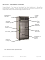
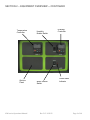
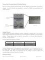
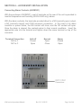
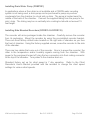
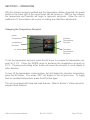
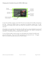
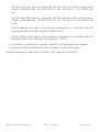
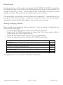
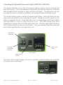
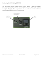
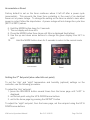
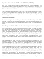
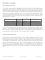
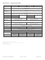
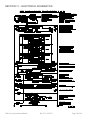
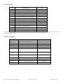
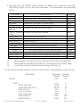
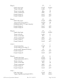
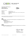
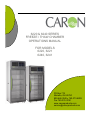
6220 & 6240 SERIES FREEZE / THAW CHAMBER OPERATIONS MANUAL FOR MODELS 6220, 6221 6240, 6241 PO Box 715 Marietta, OH 45750 800-648-3042 740-373-6809 Fax 740-374-3760 www.caronproducts.com [email protected] Dear Valued Customer: Thank you for purchasing CARON Products & Services equipment. We appreciate your business and look forward to being your preferred supplier of controlled environment equipment products in the future. At CARON, we are committed to continuous quality improvement. Our goal is to supply our customers with highly reliable equipment at a fair price. In order to openly monitor our performance, we would appreciate your feedback on our products and services. If you have questions, or any suggestions for improvement based on the installation or operation of the equipment you have purchased, please contact our service department at [email protected] or 740-373-6809. Thanks again for your business! 6200 series Operations Manual Rev D 2/14/2012 Page 2 of 60 TABLE OF CONTENTS Section 1 – Warranty .................................................................................... 5 Section 2 – Equipment Overview ................................................................. 8 Section 3 – Installation ............................................................................... 10 Unpacking Choosing a Location Preliminary Cleaning Installing the Port Stopper Installing the Shelves Leveling the Unit Connecting the Drain Line Connecting the Water Supply Connecting Electrical Power Connecting Communications and Analog Outputs Section 4 – Optional Accessory Installation ............................................. 16 Connecting Alarm Contacts (ALRM301) Installing the Carboy Water System (BOTL301) Installing the Heatless Dryer Package (DRYR301) Connecting the Fluorescent Lighting (LGHT301 & LGHT305) Installing Drain Water Pump (PUMP301) Installing the Side Mounted Recorders (RCDR314 & RCDR315) Section 5 – Operation ................................................................................. 23 Changing the Temperature Set-point Changing the Humidity Set-point Operation of the Defrost and Low Temperature Systems Operation of the Delux Controller System Section 6 – Optional Accessory Operation ............................................... 30 Using the Carboy Water System (BOTL301) Operation of the Heatless Dryer Package (DRYR301) Controlling the Fluorescent Lighting (LGHT301 & LGHT305) Controlling the LED Lighting (LGHT302) Interior Electrical Outlet (OUTL301 & OUTL302) Adjusting the Fresh Access Ports (PORT302) Operation of the Front 10” Mounted Recorders (RCDR303 / RCDR304) Operation of thermal Side Mounted Recorders (RCDR314, RCDR315) 6200 series Operations Manual Rev D 2/14/2012 Page 3 of 60 Section 7 – Calibration ............................................................................... 45 Calibrating the Temperature Calibrating the Humidity Calibrating Optional Chart Recorders Section 8 – Alarms ...................................................................................... 47 Alarm System Overview Changing Alarm Set-points Section 9 – Preventative Maintenance ...................................................... 48 Section 10 – Specifications ........................................................................ 49 Section 11 – Electrical Schematics ........................................................... 50 Section 12 – Troubleshooting .................................................................... 52 Section 13 – Spare Replacement Parts ..................................................... 53 Section 14 – Advanced Users Section ...................................................... 55 Unlocking the Controllers Locking the Controllers Appendix A – Ramp & Soak Programming Example ............................... 56 Appendix B – Declaration of Conformity .................................................. 60 6200 series Operations Manual Rev D 2/14/2012 Page 4 of 60 SECTION 1- WARRANTY INFORMATION Please review this section before requesting warranty service. At CARON, one of our primary goals is to provide customers with high levels of personal service and top quality products, delivered on time, and backed by technical service and support for the life of the product. Before contacting us for warranty service, please be aware that there are repairs that are not covered under warranty. These include: 1) Calibration of control parameters. 2) Damage resulting from improper use. 3) Service calls for improper installation including electrical service, gas and water supply tubing, gas supplies, room ventilation, unit leveling, or ambient conditions that are out of specification. 4) Customer modifications made to parts or subsystems. 5) Shipping damage either obvious or concealed as a result of freight handling. WARRANTY DEFINED Caron Products & Services, Inc. (herein after CARON) hereby warrants that equipment manufactured by CARON is free from defects in materials and workmanship when the equipment is used under normal operating conditions in accordance with the instructions provided by CARON, as follows: COVERED: Parts and labor for a period of one (1) year from date of shipment (first six digits of serial number tag contain date of shipment). Any part found defective would be either repaired or replaced at CARON's discretion, free of charge, by CARON in Marietta, OH. Parts that are replaced will become the property of CARON. This service includes diagnosis and correction of individual CARON product malfunctions, or failures, and may consist of temporary procedures to be followed by the customer while a permanent solution is sought. If CARON factory service personnel determine that the customer's unit requires further service, dependent of the model involved, CARON may, at its sole discretion, provide a service technician to correct the problem, or return the unit to the factory. If a unit is to be shipped back to the factory, CARON will pay all ground shipping charges via UPS or other common carrier. CARON will have the right to inspect the equipment and determine the repairs or replacement parts necessary. The customer would be notified, within a reasonable time after inspection, of any costs incurred that are not covered by this warranty prior to initiation of any such repairs. 6200 series Operations Manual Rev D 2/14/2012 Page 5 of 60 NOT COVERED: Cost of express shipments such as Federal Express, UPS Next Day Air, UPS Second Day Air, or any other express shipment charges. Any customer modifications of this equipment, or any repairs undertaken without the prior written consent of CARON, will render this limited warranty void. CARON is not responsible for consequential, incidental or special damages. In no event will CARON be responsible for damages more than the price of the product. Repairs necessary because of the equipment being used under other than normal operating conditions or for other than its intended use. Repair or replacement of parts due to the customer's failure to follow normal maintenance instructions. Parts considered consumable such as: light bulbs, filters, gases, etc … Damage from use of improper water quality. Damage from chemicals or cleaning agents detrimental to equipment materials. Force Majeure or Acts of God. This writing is a final and complete integration of the agreement between CARON and the customer. CARON makes no other warranties, express or implied, of merchantability, fitness for a particular purpose or otherwise, with respect to the goods sold under this agreement. This warranty cannot be altered unless CARON agrees to an alteration in writing and expressly stated herein, shall be recognized to vary or modify this contract. Ohio Law governs this warranty. Caron Products & Services, Inc. PO Box 715 · Marietta, OH 45750 740-373-6809 6200 series Operations Manual Rev D 2/14/2012 Page 6 of 60 INTERNATIONAL SYMBOLS AND DEFINITIONS ? Help i Information Warning of hazardous area Warning of hot surface Warning of dangerous electric voltage Earth (ground) protective conductor WARNINGS Local government may require proper disposal 6200 series Operations Manual Rev D 2/14/2012 Page 7 of 60 SECTION 2 – EQUIPMENT OVERVIEW Congratulations! You have just purchased the latest technology in freeze/thaw environmental chambers. Before using the equipment, familiarize yourself with key components of the product and thoroughly read this manual. Replaceable air intake filter Lockable Control Panel Power Switch Illuminated CARON Logo Adjustable Sliding Shelf Left Side Access Port Right Side Access Port Door Handle Temperature (& Humidity) Sensors Casters & Leveling Feet Note: Glass door shown; optional solid door 6200 series Operations Manual Rev D 2/14/2012 Page 8 of 60 SECTION 2 – EQUIPMENT OVERVIEW -- CON TINUED Temperature Controller Options Panel 6200 series Operations Manual Humidity Enable Switch Alarm Silence Switch Rev D 2/14/2012 Humidity Controller Visual Alarm Indicator Page 9 of 60 SECTION 3 -- INSTALLATION Unpacking Your new unit has been thoroughly packaged to avoid shipping damage. However, the unit should be fully inspected upon arrival before signing for receipt. If the package has visual damage, notes should be made on the freight bill and signed by the delivery company. In the event of concealed damage after the unit is uncrated, keep the carton and packaging material. Call the shipping company within 7 days of receipt, request inspection and retain a copy of the inspection report. Caron provides full on-site installation services for all models. Our installation services guarantees the proper set-up and startup of all equipment. Please contact the Service Department at 740-373-6809 or [email protected] for details. Choosing a Location This product weighs in excess of 500 pounds. Ensure that sufficient resources are available to safely move the product. To ensure proper operation, the unit must be located on a firm level surface, capable of supporting approximately 800 pounds. The unit should be located in an 18°C – 25°C ambient area and where there is no direct airflow from heating and cooling ducts as well as out of direct sunlight. Allow four inches of clearance on all sides of the product to allow for connections and airflow. Model 6220 / 6240 6221 / 6241 Water Source Needed Yes No Water Drain Yes *Yes * Depending on user set points, these units may not need a drain. recommended at temperatures below 15°C. Drains are The unit requires a dedicated electrical connection. Power requirements vary depending upon the chamber model, see Connecting Electrical Power section. Choose a location where these facilities are, or can be made available. If a water source, or a drain is not available, contact CARON customer service and ask about our CRYS102 product line or click this weblink for information on the product: http://www.caronproducts.com/65 6200 series Operations Manual Rev D 2/14/2012 Page 10 of 60 Preliminary Cleaning Your new environmental chamber was thoroughly cleaned prior to leaving the factory. It is recommended however, to disinfect all interior surfaces with a general purpose laboratory cleaning agent prior to using the product. After cleaning, dry all interior components with a sterile cloth as necessary. Installing the Port Stoppers The unit has an access port built into each side of the cabinet. The ports are designed to allow customer access for equipment validation and for installation of other equipment inside the chamber. These ports should be sealed with the provided rubber stoppers to allow the chamber to function properly. Install the stoppers provided in the port on each side of the unit. Installing the Shelves Each new environmental chamber includes four or five perforated stainless steel shelves. Each shelf requires two shelf channels for installation. The left and right shelf tracks are the same. Prior to installation, take time to consider what the size of the product being placed in the chamber will be and set the shelf spacing accordingly. Additional shelving can be purchased through CARON customer service if necessary. To install the shelf channels insert the rear tab on the shelf channel into the rear wall on the side wall of the chamber. Then insert the front tab into the front pilaster. Push the entire shelf channel towards the rear of the unit and snap it down into place. Each shelf is capable of supporting a uniformly distributed load of 50 pounds. The maximum chamber capacity is 500 pounds (stationary). An optional re-enforced floor is available for heavy loads. Chamber should be empty when being moved. Do not have multiple loaded shelves out simultaneously or the chamber may tip. 6200 series Operations Manual Rev D 2/14/2012 Page 11 of 60 Leveling the Unit Place a level on the middle shelf of the incubator. Adjust the feet until the unit sits level left to right and front to back. Even if the unit is level without adjustment, the leveling feet should still be lowered to avoid the cabinet moving while opening and closing the outer door & prevent a flat spot from forming on the casters. Connecting the Drain Line When using a pressurized water source, failure to connect the unit to a drain could result in facility flooding. The chamber drain connection is located in the bottom middle of the back of the chamber. A 3/8” NPT fitting and tubing are supplied in the unit parts kit. Thread the fitting into the drain connection and slide the tubing into the drain connection. Pull on the tubing after installation to make sure it is tight. Route the drain tubing to a local floor drain. The drain line relies on gravity to remove water from the chamber. The drain line must remain below the chamber to drain properly. Kinks or elevations in the drain line above the cabinet drain will not allow the chamber to drain. If a local floor drain is not available, a variety of accessories are available through CARON customer service. These accessories can also be viewed at www.caronproducts.com. For non-humidified chambers operated above 15°C, a drain is not needed. Install the 3/8” plug into the drain connection. Connecting the Water Supply To ensure proper operation, distilled or deionized water is required as a supply on units that have humidity control. If these water sources are not available contact CARON customer service. 6200 series Operations Manual Rev D 2/14/2012 Page 12 of 60 Use only distilled or deionized water with a resistivity between 50K-CM and 1M-CM and a pH of greater than 6.5. Using water outside this range will void your warranty. Do not use water that contains chloramines. Chloramines can damage internal rubber gaskets resulting in leaks. A water inlet fitting on the back of the unit and ¼” black tubing are provided to connect the water supply to the chamber. Connect an appropriate water supply to the fitting. Incoming line pressure should be regulated to not exceed 80 psi. If a Condensate Recirculator water recycling system was purchased as a water supply, refer to its user’s manual for proper installation of the water supply. Connecting Electrical Power Connect each chamber to a grounded circuit. Failure to do so could result in electrical shock. The unit requires a dedicated electrical outlet. See table below for model specific power required and connection. Model # -2 -3 Power Requirements 230V, 60Hz, 12A FLA 230V, 50Hz, 10A FLA Plug Connection NEMA 6-15 CEE 7/7 When the required electrical connection is available, plug the provided power cord into the unit and the electrical outlet. 6200 series Operations Manual Rev D 2/14/2012 Page 13 of 60 Connecting Communications & Analog Outputs This unit comes standard with features such as RS485 communications and analog outputs. A set of terminals are provided to connect to RS485 communications and analog outputs. Analog Outputs Analog outputs are either milliamps (0-20mA, 4-20mA) or voltage (0-5V, 1-5V, 0-10V, 0-20V) signal output that represents each of the displayed temperature (and humidity) values. These options can be used for connection to in-house data acquisition, recorder, or alarm system. Factory default settings are as follows: Parameter Temperature Humidity Analog Output 0–5V 0–5V Corresponding Value -50 – 100 °C 0 – 100 %rh Connect shielded wires to the appropriate signal terminals: I(+) for current (mA) or V(+) for voltage (DC). For both current and voltage outputs, COM(-) is common terminal. The controller itself must be programmed for the voltage or current signal and corresponding scale (see Operations Section) Communications 6200 series Operations Manual Rev D 2/14/2012 Page 14 of 60 RS-485 communications are intended to communicate with a PC using ModBus RTU or Standard Bus. The maximum number of chambers connected to a single PC is limited to 247 controllers (Modbus) or 16 controllers (Standard Bus). Chambers 6221 & 6421 have one controller each. Chambers 6220 & 6420 have two controllers each. Connect shielded wires to the RS-485 Communications terminal blocks. Communications wires should be shielded and routed away from power wires. Maximum distance of total wire is 2000 feet. When connecting multiple chambers, route wires in a daisy chain fashion. A termination resistor of 120 ohms may be placed across RS-485(-) and RS-485(+) of the last chamber in the daisy chain. For PC’s having an RS-232 serial port (9-pin D-Sub) connection, an RS-485 to RS-232 converter may be used. Recommended sources are B&B Electronics (P/N 4850I9TB) and CMC-Connecticut Micro Computer (ADA485L). SFTW301 software is available from CARON to load onto a PC to monitor and record data. This data storage is not 21CFR Part 11 compliant. 6200 series Operations Manual Rev D 2/14/2012 Page 15 of 60 SECTION 4 – ACCESSORY INSTALLATION Connecting Alarm Contacts (ALRM301) With the purchase of ALRM301, a set of terminals on the rear of the unit is provided to monitor temperature and humidity (6220 & 6240 only) alarms. With the alarm contacts, the terminals provided allow for a NO (normally open) output, a NC (normally closed) and COM (common) connection. In the event of an alarm condition or power failure, the NO contact will close, and the NC contact will open. Once the alarm is cleared, the contacts return to their normal conditions. Insert the appropriate wire into the terminal and tighten down the screw terminal on top of the connector. Terminal Connection N/O to C N/C to C 6200 series Operations Manual Unit off Closed Open Normal Open Close Rev D 2/14/2012 Alarm Closed Open Page 16 of 60 Installing Carboy Water System (BOTL301) Models 6220 & 6240 can be purchased with an optional 2.5 gallon carboy water system. The carboy system is preassembled and shipped inside the chamber. The four ¼” bolts required to mount the carboy to the unit will be mounted in the left hand side of the chamber. Remove the carboy assembly from inside the chamber and attach it to the chamber using the ¼” bolts. ¼” Bolts (4 total) Tubing connects/ disconnect to carboy Attach the preassembled tubing provided with the carboy to the water inlet on the rear of the chamber. Tubing to water inlet Fill the carboy with water as described in the “connecting a water supply” section of the manual. 6200 series Operations Manual Rev D 2/14/2012 Page 17 of 60 Installing the Heatless Dryer Package (DRYR301) The Heatless Dryer Package extends the operational limits to a minimum humidity control point of 2% RH and improves the dehumidification rate by purging the chamber with dry air. Air flows through the Dryer Package only when dehumidification is required to maintain the humidity set point. It uses compressed air at 90 to 100 psig to operate. Maximum airflow required is 480 SCFH (8 CFM). Of this 300 SCFH (5 CFM) is injected into the chamber as dry air and 180 SCFH (3 CFM) is exhausted into the room after being used to regenerate the desiccant. Particles of dirt or rust, as well as large amounts of condensed moisture or oil that may be in the compressed air line feeding the dryer must be removed from the air stream before it enters the dryer. Dryer Panel Tower Clamps (optional) Power Cord Air Tube Mounting Brackets Flow Meter Outlet Air Supply Inlet Pressure Regulator Knob Flow Meter Adjustment Coalescent Filter With Drain 6200 series Operations Manual Pressure Regulator Dial Rev D 2/14/2012 Page 18 of 60 Incoming compressed air must be free of dirt, oil, moisture and filtered to 10 microns minimum. Incoming compressed air must not exceed 100 psig. CARON recommends installing a pressure gauge, filter, and shutoff prior to the dryer to monitor incoming air pressure. The air supply (either house air or other compressed air source) must be 90 to 100psig at the air supply inlet. An oil-less compressor may be used. A Sound Suppression Kit maybe used to reduce the dryer noise (contact CARON service for details). 1. Attach Dryer Package to exterior chamber with four mounting screws. Mounting Screws Mounting Screws 2. Connect dryer package power cord and 3/8” orange tubing into the dryer panel on the chamber Power Cord Connection Tube Connection 6200 series Operations Manual Rev D 2/14/2012 Page 19 of 60 3. Attach 3/8” orange tubing from the chamber to the flow meter outlet. Flow Meter Outlet 4. Connect compressed air to dryer package inlet fitting (1/4 NPT) Dryer Inlet See Operations section of the manual for instructions on setting the pressure regulator and flow meter. 6200 series Operations Manual Rev D 2/14/2012 Page 20 of 60 Connecting the Fluorescent Lighting (LGHT301 & LGHT305) Chambers with optional fluorescent lighting have light banks consisting of two lamps each. 6220 series models have three independent light banks and 6240 series models have four light banks on two independent controls. The light banks are suspended to the shelf underside. The lights shipped fully installed in place from the factory. See the Operations or Maintenance sections of the manual for more details. Lights should only be used in a non-condensing environment. Light Bank Wires Light Banks 6200 series Operations Manual Rev D 2/14/2012 Page 21 of 60 Installing Drain Water Pump (PUMP301) In applications where a floor drain is not available and a CARON water recycling system is not being used, a drain pump can be purchased to pump any excess condensate from the chamber to a local sink or drain. The pump is located near the middle of the back of the chamber. Connect the supplied tubing from the pump to the sink / drain. The tubing may be run vertically into a ceiling but should not exceed 15 feet height. Installing Side Mounted Recorders (RCDR314 & RCDR315) The recorder will arrive packaged inside the chamber. Carefully remove the recorder from its packaging. Mount the recorder by using the pre-installed recorder bracket. There are three factory drilled holes located on the right side of chamber as you face the front of chamber. Using the factory supplied screws, screw the recorder to the side of the chamber. There are two cables that come out of the recorder. One is to power the recorder; the other is the temperature and/or humidity signals coming from the chamber. With power to the equipment turned off, plug the two connectors into their mating connector at the top of the chamber. Turn power to the chamber back on. Standard factory set up for chart speed is 7 day operation. Refer to the Chart Recorder’s User’s Manual provided with the recorder to change the chart speed settings for various chart speeds. 6200 series Operations Manual Rev D 2/14/2012 Page 22 of 60 SECTION 5 – OPERATION With the chamber properly installed and the appropriate utilities connected, the power switch on the lower right of the control bezel can be turned on. Within a few minutes, the temperature and humidity will begin to approach set-points. Allow the unit to stabilize for 12 hours before use or prior to making any calibration adjustments. Changing the Temperature Set-point Actual Temperature Increase Temperature Set-point Temperature Set-point Decrease Temperature Set-point EZ Button To set the temperature set-point, press the UP arrow to increase the temperature setpoint by 0.1C. Press the DOWN arrow to decrease the temperature set-point by 0.1C. Pressing and holding either button will cause the set-point to scroll rapidly in either direction. To turn off the temperature control system, but still display the chamber temperature, press the EZ button. The words “OFF” will display in the set-point area. To toggle back to controlled temperature, press the EZ button again. The unit is equipped with ramp and soak features. Refer to Section 7 of the manual to program these features. 6200 series Operations Manual Rev D 2/14/2012 Page 23 of 60 Changing the Humidity Set-point (6220 & 6240 only) Actual Humidity Increase Humidity Set-point Humidity Set-point Enable Humidity Control Switch Decrease Humidity Set-point EZ Button To set the humidity set-point, press the UP arrow to increase the humidity set-point by 1% RH. Press the DOWN arrow to decrease the humidity set-point by 1% RH. Pressing and holding either button will cause the set-point to scroll rapidly in either direction. If humidity is not required in the chamber, the RH system can be disabled by turning off the Enable Humidity switch. This will disable the entire RH system including the controller. The system can be turned back on at anytime. To turn off the humidity control system, but still display the chamber humidity level, press the EZ button. The words “OFF” will display in the set-point area. To toggle back to controlled humidity, press the EZ button again. 6200 series Operations Manual Rev D 2/14/2012 Page 24 of 60 Operation of the Defrost / Low Temperature System A Defrost System is used to maintain operational temperature below 5ºC. When the chamber temperature is below 4.5ºC, the defrost system is enabled automatically. When the chamber temperature is above 4.5ºC (except during a defrost cycle), the defrost system is disabled automatically. When the defrost system is enabled (below 4.5ºC), a defrost cycle will occur once every 96 hours and lasts for 20 minutes. During the defrost cycle, the chamber temperature will increase several degrees above set point to melt any ice that has formed on the evaporator. This temperature ‘spike’ is normal and assures long-term operation. Operation in Low Temperature Mode (6220 & 6240 only) When the chamber is operating at temperatures below 4.5C, it automatically enters the Low Temperature Mode. In this mode, the humidity control and display is disabled because of the risk of water freezing and causing damage. When in low temperature mode, the humidity controller will not turn on and the yellow ‘inactive’ light will illuminate when the humidity switch is turned on. 6200 series Operations Manual Rev D 2/14/2012 Page 25 of 60 Operation of the Delux Controller System The chambers can be purchased with upgraded controllers. The controllers have additional features of RS485 communications, analog outputs, and ramp & soak. RS485 Communications: Each controller on the network (connected to the same PC or master device) must be programmed with a unique address. If multiple chambers are being connected, each controller will have to be assigned a unique address. Factory defaults for the controllers are addresses 1 for temperature and 2 for humidity. As an example, a second chamber would need to be assigned address 3 for temperature and 4 for humidity. To assign new addresses to controllers, the controllers must be unlocked. Refer to Section 13, Unlocking the Controllers. Once the controllers are unlocked on each controller, follow these steps to set a unique address for each controller: 1) 2) 3) 4) 5) 6) 7) 8) 9) 10) 11) 12) 13) 14) Press and hold the up and down key simultaneously for six seconds. The upper display will read Ai and the lower will read SEt Press the up key until the upper display reads CoM Press the advance key until PCoL appears Set the protocol to either Modbus (Mod) or Standard Bus (Std) Press the advance key until Ad.M (Modbus) or Ad.S (Standard) appears Press up/down to increase/decrease the address number *Press the advance key until bAUd appears *Press the up/down arrow keys to set the baud rate (38.4K is default) *Press the advance key until Par appears *Press the up/down arrow keys to set the Parity (‘none’ is default) *Press the advance key until M.hL appears *Press the up/down arrow keys to set the Word Order (‘Lohi’ is default) Press infinity to exit to the main menu *When using ModBus, other parameters such as Baud Rate, Parity, and Word Order must be set. Standard Bus only requires a unique address be set. Once all addresses are entered refer to Section 13 to relock the controllers. 6200 series Operations Manual Rev D 2/14/2012 Page 26 of 60 Analog Outputs: With DLUX301 & DLUX302 controllers, there is an analog output signal for temperature and humidity which represents the actual chamber values. This allows the chamber to be connected to an in-house data acquisition or alarm system. The analog signal outputs are selectable as either voltage DC or milliamp. In both cases, the output is scalable from 0.0 to 20.0. Common settings are 0-1V, 0-5V, 1-5V, 0-10V, 0-20mA, and 4-20mA. The factory default settings are 0-5V. For each selected output range, a temperature and humidity value must correspond to the high and low range. This range should be large enough to encompass the entire chamber possible values and small enough to provide adequate resolution. The analog outputs can be calibrated by placing an offset into the controller. This offset affects only the analog outputs and not the controller displayed value. To change the controller displayed value, see the calibration section in the manual. To change the factory defaults of the controllers, the controllers must be unlocked. Refer to Section 14, Unlocking the Controllers. 1. 2. 3. 4. 5. Pressing the up and down keys simultaneously for 6 seconds. Press the up key until otPt is displayed Press the advance key until the upper display reads 1 Press the up button until 3 is displayed Press the advance button to scroll through the parameters; use the up and down arrow buttons to change the parameters. Factory default parameters are listed below Parameter Description Type Function Retransmit Source Scale Low Scale High Range Low Range High Calibration Offset Display o.tY Fn r.Sr S.Lo S.hi r.Lo r.hi o.CA Value Volt rMt Ai 0.00 5.00 0.0 100.0 0.0 For a DC volt output, set the Type to “Volt” For a mA output, set the Type to “MA” 6200 series Operations Manual Rev D 2/14/2012 Page 27 of 60 Set the Scale Low value to correspond with the minimum value of the process output in electrical units. For 0-5V, set to 0. For 1-5V, set to 1. For 4-20mA, set to 4. Set the Scale High value to correspond with the maximum value of the process output in electrical units. For 0-5V, set to 5. For 1-5V, set to 5. For 4-20mA, set to 20. Set the Range Low value to the minimum temperature (or humidity) that will correspond with the Scale Low value (default is 0.0). Set the Range High value to the maximum temperature (or humidity) that will correspond with the Scale High value (default is 100.0). 6. If an offset (or calibration) is needed, adjust the o.CA parameter accordingly 7. Press and hold the infinity button for 2 seconds to exit to home page Once all changes are made refer to Section 14 to relock the controllers. 6200 series Operations Manual Rev D 2/14/2012 Page 28 of 60 Ramp & Soak: A ramp and soak control system is included with DLUX301 & DLUX302 controllers. This allows the user to store up to 40 steps spanning 4 profiles. A step consists of a change in set-point (or ramp). Another step is used to maintain a set-point for a fixed duration (or soak). Steps can also be repeated any number of times. The temperature and humidity control systems are independent. Temperature can run through a profile while humidity is maintained constant and visa versa. By starting the temperature and humidity profile together, the controls can run in-sync. Starting / Stopping a Profile Once a profile is programmed into the controller, it may be started or stopped at any time from the home page. 1. Press the ADVANCE button several times until P.St1 appears 2. Use the UP or DOWN arrow keys to choose the file or step number within a profile where you want to begin running 3. Press the ADVANCE button one time; P.AC1 should display 4. Select the appropriate action with the UP & DOWN arrow keys: Parameter Description No action Begin execution from first step of the specified profile number Pause the currently running profile Resume running the profile from the previously paused step End the profile Begin running the profile from the specified step number Display nonE ProF PAUS rESU End StEP See Appendix A for an example of a Ramp & Soak profile. 6200 series Operations Manual Rev D 2/14/2012 Page 29 of 60 SECTION 6 – ACCESSORY OPERATION Using the Carboy Water System (BOTL301) To fill the carboy while attached to the chamber, unscrew the cap. Fill carboy with distilled or deionized water (see Connecting the Water Supply section for details). The carboy holds 2.5 liters. If the carboy must be removed in order to fill it up, first disconnect the tubing between the carboy and chamber by pressing the metal lever at the tubing connects / disconnects at the bottom of the carboy. Then unscrew the four mounting screws and remove the carboy. After re-attaching the carboy, connect the tubing by simply pressing the plastic fittings into each other. Screw Cap Mounting Screws (4 total) Tubing Connects/ Disconnect to Carboy Tubing To Chamber 6200 series Operations Manual Rev D 2/14/2012 Page 30 of 60 Operation of the Heatless Dryer Package (DRYR301) The flow meter shows the flow rate of dry air entering the chamber. It is adjustable by the knob at the bottom of the meter. Maximum performance is obtained at 300 SCFH (or 5 CFM). Operating the unit above or below this purge rate may decrease performance!! A pressure regulator is installed between the tower dryers and glass flow meter to limit the pressure into the flow meter. The regulator should be set at a maximum of 100psi. 1. Open the chamber door and set the humidity set point to 0% 2. Turn the flow meter adjustment knob OFF 3. Adjust the pressure regulator knob so the pressure regulator dial indicates 90 psig maximum. (Pull up on the knob to adjust, push down on the knob to lock) 4. Adjust the flow meter adjustment knob so the flow is 300 SCFH. The dryer will purge the chamber with compressed air only when dehumidification is needed to reach the humidity set point. 6200 series Operations Manual Rev D 2/14/2012 Page 31 of 60 Controlling the Optional Fluorescent Lights (LGHT301 & LGHT305) The diurnal chamber comes with a fluorescent lighting system used to simulate day and night testing. There are separate temperature and humidity (optional) set-points that correspond with the lights on (day) and lights off (night). The set-points can also be made the same if continuous conditions are needed throughout the light cycles. The diurnal lighting system consists of separate light banks. Each light bank has two lamps and is mounted on the underside of a shelf. The banks can be located on the same or separate shelves. Each light bank has a corresponding switch that enables that light bank to come on when the timer is on. The 6220 series have three independent controls while the 6240 series have two. Only the light banks that have their individual switch turned on will illuminate. The green indicator light above the light bank switch signifies when each light bank is on. Light Bank Indicators Individual Light Bank switches Light Cycle Timer Light Power Switch 6240 Series The timer can be used to trigger an event in a profile to switch between two set-points (if programmed accordingly). 6220 Series 6200 series Operations Manual Rev D 2/14/2012 Page 32 of 60 Operating the timer The power switch enables and disables the lights and cycle timer. When the timer is “on”, the 2nd set-point (also known as “idle set point”) on the controllers is enabled as well as the lights. The timer will display “OUT” corresponds to lights being enabled. The timer has an adjustable “on” and “off” cycle times which repeat continuously. SET1 corresponds to the lights “on” cycle time and SET2 to the lights “off” cycle time. Present accumulated time Lights on status indicator Cycle Time on (or off) Cycle time display indicator MODE button RESET button Cycle time adjustment buttons Setting the cycle timer 1. With the Light Power Switch ‘on’, press the MODE button until SET1 is displayed 2. Using the up and down cycle time adjustment buttons, set the lights ‘off’ cycle timer to the desired time in the format hh:mm. Maximum time is 99hrs 59min. 3. Press the MODE button; cycle time display indicator switches to SET2. 4. Using the up and down cycle time adjustment buttons, set the lights ‘on’ cycle timer to the desired time in the format hh:mm. For continuous lights ‘on’ operation, set the SET2 cycle time to 00:00. Maximum time is 99hrs 59min. Press the RESET button to reset the timer so it starts at the beginning of the lights off cycle. Press the MODE button to toggle between lights on (SET1) and lights off (SET2) times 6200 series Operations Manual Rev D 2/14/2012 Page 33 of 60 Accumulate or Reset Factory default is set so the timer continues where it left off after a power cycle (accumulate). This prevents the timer from re-starting in the event of an electrical brown-out or power outage. To change the setting so the timer re-starts to zero when power is cycled, follow the steps below. A power outage will not change the cycle time (SET1 & SET2) values. 1. 2. 3. 4. Hold the MODE button down for 3 seconds The red display will show ōFtr. Press the MODE button three times until tōtm is displayed 9red letters) Use the up and down arrow buttons to change the green display from tōF1 to tōFF 5. Hold the MODE button down for 3 seconds to return to the normal mode Accumulate Reset Setting the 2nd Set-point (also called idle set point) To set the “day” and “night” temperature and humidity (optional) settings on the controller, use the following procedure. To adjust the “day” set-point: 1. press the ADVANCE button several times from the home page until “id.S1” is displayed. 2. set the set-point using the UP & DOWN arrow buttons 3. exit to the home page by pressing the INFINITY button To adjust the “night” set-point from the home page, set the set-point using the UP & DOWN arrow buttons 6200 series Operations Manual Rev D 2/14/2012 Page 34 of 60 Controlling the LED Lighting (LGHT302) The LED lighting system creates low-level internal lighting. There are separate temperature and humidity (optional) set-points that correspond with the lights on (day) and lights off (night). The set-points can also be made the same if continuous conditions are needed throughout the light cycles. Lighting System Power Switch Lights On Indicator Light 6200 series Operations Manual Light Timer Rev D 2/14/2012 Page 35 of 60 Operating the timer The power switch enables and disables the lights and cycle timer. When the timer is “on”, the 2nd set-point (also known as “idle set point”) on the controllers is enabled as well as the lights. The timer will display “OUT” corresponds to lights being enabled. The timer has an adjustable “on” and “off” cycle times which repeat continuously. SET1 corresponds to the lights “off” cycle time and SET2 to the lights “on” cycle time. Present accumulated time Lights on status indicator Cycle Time on (or off) Cycle time display indicator MODE button RESET button Cycle time adjustment buttons Setting the cycle timer 1. With the Light Power Switch ‘on’, press the MODE button until SET1 is displayed 2. Using the up and down cycle time adjustment buttons, set the lights ‘off’ cycle timer to the desired time in the format hh:mm. Maximum time is 99hrs 59min. 3. Press the MODE button; cycle time display indicator switches to SET2. 4. Using the up and down cycle time adjustment buttons, set the lights ‘on’ cycle timer to the desired time in the format hh:mm. For continuous lights ‘on’ operation, set the SET2 cycle time to 00:00. Maximum time is 99hrs 59min. Press the RST button to reset the timer so it starts at the beginning of the lights off cycle. When resetting the timer, it automatically begins with the lights “off” cycle first. Press the MODE button to toggle between lights on (SET1) and lights off (SET2) times 6200 series Operations Manual Rev D 2/14/2012 Page 36 of 60 Examples for how to start your timer during day or night modes Night Start Procedure: 1. Set the timer to SET 1 2. Enter the length of time you would like the lights off (night setting) Example 12 Hrs. 3. Set the timer to SET 2 4. Enter the length of time you would like to have the lights on (day setting) Example 12 Hrs. 5. Determine what time you would like to have the timer change between day/night 6. Example 7:00 P.M. switch to night setting (lights off) 7. At 7:00 P.M. press the RST button on the timer 8. Timer is now set to run with lights off from 7:00 P.M. to 7:00 A.M. and programmed to turn the lights on from 7:00 A.M. to 7:00 P.M. Day Start Procedure: To start the same profile using the example above, follow these steps to start your lights in day mode 1. Set the timer to SET 2 2. Enter the length of time you would like to have the lights on (day setting) Example 12 Hrs. 3. Change SET 1 from 12 Hrs. down to 1 minute 4. At 6.59 A.M., Press the RST button 5. The timer will start and the lights will be off for 1 minute 6. Once the lights turn on, change the SET 1 from 1 minute to 12 Hrs 7. Do NOT press the RST button 6200 series Operations Manual Rev D 2/14/2012 Page 37 of 60 Accumulate or Reset Factory default is set so the timer continues where it left off after a power cycle (accumulate). This prevents the timer from re-starting in the event of an electrical brown-out or power outage. To change the setting so the timer re-starts to zero when power is cycled, follow the steps below. A power outage will not change the cycle time (SET1 & SET2) values. 6. 7. 8. 9. Hold the MODE button down for 3 seconds The red display will show ōFtr. Press the MODE button three times until tōtm is displayed 9red letters) Use the up and down arrow buttons to change the green display from tōF1 to tōFF 10. Hold the MODE button down for 3 seconds to return to the normal mode Accumulate Reset Setting the 2nd Set-point (also called idle set point) To set the “day” and “night” temperature and humidity (optional) settings on the controller, use the following procedure. To adjust the “day” set-point: 1. press the ADVANCE button several times from the home page until “id.S1” is displayed. 2. set the set-point using the UP & DOWN arrow buttons 3. exit to the home page by pressing the INFINITY button To adjust the “night” set-point, from the home page, set the set-point using the UP & DOWN arrow buttons 6200 series Operations Manual Rev D 2/14/2012 Page 38 of 60 Interior Electrical Outlet (OUTL301 & OUTL302) An optional interior duplex electrical outlet is available to supply power to small interior appliances such as shakers or stirrers. It is not intended to power high current draw devices. The outlet is 115V and GFI protected. For chambers that have a single interior duplex outlet, the outlet is fused at 2.0 Amps. Chambers with two interior duplex outlets are fused at 4.0 Amps total. Adjusting the Fresh Air Ports (PORT302) Fresh air ports facilitate air exchange between the chamber interior and room air. The ports are intended to be used together; air enters through one port and out the other. The amount of air exchange is controlled by opening the ports at various amounts. If no air exchange is desired, screw both ports in all the way. 6200 series Operations Manual Rev D 2/14/2012 Page 39 of 60 Operation of Front Mounted 10” Recorders (RCDR303, RCDR304) Built in 10” thermal pen recorders can be purchased with CARON chambers. The recorders are shipped installed on the outer door of the chamber from the factory and require no further installation. Unlike ink pen recorders, the thermal recorders draw their own chart and control lines. The 10” recorders have been setup at the factory in the following configuration: 7 Day / 24 Hour / Temperature 0-100°C / Humidity 0-100% (for dual input recorders). If this is not the ideal configuration for an application, the recorder may be reconfigured using the following process: Configuring the recorder: In order to configure the recorder, you will need to enter the set-up mode of the recorder. To enter the set-up mode of the recorder, press and hold the Change Chart button (#3) until the thermal pen arm begins to move off scale and then release the button. Note: The green LED light will flash fast while the thermal pen arm is moving off scale. Wait until the thermal pen arm has moved completely off scale and stops (the green LED light will stop flashing and will be steady On). Unscrew (counter clockwise) the chart "hub" knob at the center of the chart and remove the recording chart paper. Gently lift the thermal pen arm just enough to be able to slide the paper out from beneath it. Remove the recording chart paper and place the Setup Chart onto the recorder. This chart contains the configuration categories of the recorder (Probe Input, Inner Chart Temperature, Outer Chart Temperature, Temperature Scale, Chart Rotation Speed, Input Filtering, Optional Relay Contacts and Date/Time for internal clock). Next, press and hold either button #1 or #2 until the green LED light goes out and release the button. If this step is successfully completed, the pen arm will move to the outermost graduation ring of the Setup Chart. Use the Left (#1) or Right (#2) arrow buttons to adjust the center of the thermal pen to be on this outermost graduation ring. Position the Setup Chart so that the tip of the thermal pen is in the center of the Start circle. Tighten the chart hub knob to secure the chart in place. Next, press and release the Change Chart button to begin. The chart will rotate to the first category (Input #1). Use the Left and Right arrow buttons to move the thermal pen arm to the desired option of each category. Press and release the Change Chart button to accept the selection and advance to the next category. You must press and release the Change Chart button when you have finished configuring the last category in order to 6200 series Operations Manual Rev D 2/14/2012 Page 40 of 60 save all of the changes that have been made to the recorder's configuration. The thermal pen arm will move off of the chart allowing you to place the recording chart paper onto the recorder. Press and release the Change Chart button to begin recording. Changing the Chart Paper: Press and hold the Change Chart button (#3) for approximately one (1) second until the pen begins to move off scale and then release the button. Note: The green LED light will flash fast while the thermal pen arm is moving off scale. Wait until the thermal pen arm has moved completely off scale and stops (the green LED light will stop flashing and will be steady On). To remove the chart paper, unscrew (counter clockwise) the chart "hub" knob at the center of the chart. Gently lift the thermal pen arm just enough to be able to slide the paper out from beneath it. Remove the old recording chart paper and position a new one. Re-attach the chart "hub" knob and screw securely (by hand) against the chart. Press and hold the Change Chart button (#3) again for approximately one (1) second and the thermal pen arm will move back onto the chart and begin recording. Green Light LED Status: The green LED light (located just below the three button membrane switch) is used to show the recorder's status: 1.) LED on steady (not flashing) and input(s) recording within chart range, indicates unit is recording normally. 2.) LED on steady (not flashing) and pen arm above outermost graduation and not moving, indicates recorder is in Change Chart mode. Press and release Change Chart button to return to normal recording mode. 3.) LED flashing rapidly and one or both inputs recording at outermost or innermost graduation indicates a sensor break. Check or replace sensor(s). If sensor(s) are ok, make sure process temperature is within configured range of recorder. 4.) LED flashing slowly (.8 seconds ON / .8 seconds OFF) indicates recorder is in Set-Up mode. Refer to section CONFIGURING THE RECORDER. 5.) LED is Off indicates that there is no power to the recorder. Check A/C power to the recorder. 6200 series Operations Manual Rev D 2/14/2012 Page 41 of 60 Recorder Calibration: If calibration is required for single input recorders, use the Left (#1) and Right (#2) arrow buttons on the recorder to calibrate the temperature being recorded on the chart to correspond to the temperature of the solution. The arrow buttons must be held for approximately eight (8) seconds before the pen begins to move. If calibration is required for dual input recorders, you must first select the input that you wish to calibrate. This is done by pressing and holding the Left (#1) arrow button to select Input #1 or the Right (#2) arrow button to select Input #2. The arrow button must be held down until the green LED light turns off, after which follow the instructions in single input instructions above. Maximizing Pen Life: In order to maximize the amount of life expected out of the thermal pen tip, follow these simple rules: 1) Never let the thermal pen tip ride on the chart plate when the chart paper is not present. This will damage the protective coating of the heating element. 2) Never use chart paper that is creased or that has been folded. 3) Periodically clean the thermal pen tip with a cotton swap dipped in alcohol. Clean more often when operating the recorder in a dusty environment. 4) Always keep the door closed while the unit is recording. 5) Never lift the pen arm more than is necessary to remove and replace the chart paper. Excessive lifting may cause a decrease in the pen tip pressure and cause light printing. 6200 series Operations Manual Rev D 2/14/2012 Page 42 of 60 Operation of Thermal Side Mounted Recorders (RCDR314, RCDR315) Side mounted Honeywell DR 4500 Truline Circular Chart Recorders are also available with CARON chambers. This chart recorder uses reliable microprocessor operation to generate dependable thermal traces on universal 12-inch (310 mm) charts. The twoinput models (RCDR315) accepts inputs from a temperature sensor and a humidity sensor. The single-input model (RCDR314) records temperature only. The recorders are housed in a molded case with a glass windowed, gray gasketed door which protects internal components while allowing easy access to the chart. Routine Maintenance: The recorder does not require any periodic maintenance. However, the chart paper will have to be replaced as required. Replacing the chart: To replace a chart or start a new one, follow the steps below: 1. Turn the knob on the door and swing the door open 2. Press the CHART button to temporary put the chart in ‘hold’ mode 3. Pull up on the arm lifter to raise the arm from the chart plate. NOTE: DO NOT LIFT THE ARM DIRECTLY 4. Lift the paper off the hub and slide it out from under the arm to remove it from the chart plate. 5. Slip the new chart (writing near center circle facing you) under the arm and place over the chart hub. Press the paper locator hole over the hub locator pin 6. Tuck the paper under the edge tabs. 7. Push the arm lifter back down. 8. Press the CHART button to start recording on the new chart paper. 9. Close the door. Adjusting the chart speed: The chart speed as shipped from the factory is set for a 7 day cycle. It can be changed to a 24 hour cycle or any amount between 6 hours and 1 month. To change the chart speed: 1. Turn the knob on the door and swing the door open 2. Press the CHART button to temporary put the chart in ‘hold’ mode 3. Press the SETUP button until ‘CHART’ is displayed 6200 series Operations Manual Rev D 2/14/2012 Page 43 of 60 4. Press the FUNC button and ‘CHRT SPD’ will show 5. Use the up and down arrow keys to select one of the standard settings (8 hr, 12 hr, 24 hr, 7 days) or ‘x HR’ to specify a unique speed. 6. If specifying a unique speed, press the FUNC button and use the up and down arrow keys to set the chart speed in hours (6 to 744). 7. Press the LOWR DISP button to return to the main display. 8. Press the CHART button to start recording at the new speed. 9. Close the door. 6200 series Operations Manual Rev D 2/14/2012 Page 44 of 60 SECTION 7 – CALIBRATION The temperature and humidity systems can all be calibrated as necessary. CARON recommends an annual calibration check of each system. Before making a calibration adjustment, allow the cabinet to stabilize a minimum of 12 hours from a power off condition. If the unit has been in operation, allow a minimum of 3 hours of stable operation at all set-points. If you do not have the appropriate reference instruments to perform calibration, contact CARON’s service department for on-site calibration at [email protected]. Caron also provides validation services which ensures that the unit is functioning properly according to IQ, OQ and PQ protocols which satisfy FDA guidelines for qualification verification of equipment. Be sure that all reference instruments are calibrated to an appropriate standard. Calibrating the Temperature If temperature calibration is needed, the following steps can be taken: Infinity Key Advance Key Locate the reference instrument’s temperature sensor in close proximity to the cabinet’s geometric center. Be sure that the stabilization times described earlier have been satisfied prior to performing calibration. Press the advance key until the green display reads i.CAL (calibrate). Pressing the UP arrow will increase the Temperature calibration offset by 0.1C. Pressing the down arrow will decrease the Temperature calibration offset by 0.1C. Pressing and holding either button will rapidly scroll the calibration offset. When finished, press the infinity key to return to the main menu. Temperature calibration example If the chamber temperature display reads 40.0C and the calibrated independent sensor shows 40.3C, set the i.CAL offset value to 0.3C. If the calibrated independent sensor shows 39.6C, then the entered offset should be negative. In this example the required offset to i.CAL would be -0.4C. 6200 series Operations Manual Rev D 2/14/2012 Page 45 of 60 Calibrating the Humidity If humidity calibration is needed, the following steps can be taken: Infinity Key Advance Key Locate the reference instrument’s temperature sensor in close proximity to the cabinet’s geometric center. Be sure that the stabilization times described earlier have been satisfied prior to performing this calibration. Press the advance key until the green display reads i.CAL (calibrate). Pressing the UP arrow will increase the Humidity calibration offset by 1%. Pressing the down arrow will decrease the Humidity calibration offset by 1%. Pressing and holding either button will rapidly scroll the calibration offset. When finished, press the infinity key to return to the main menu. Humidity calibration example If the chamber temperature display reads 80% and the calibrated independent sensor shows 83%, set the i.CAL offset value to 3.0%. If the calibrated independent sensor shows 74C, then the entered offset should be negative. In this example the required offset to i.CAL would be -6.0%. Calibrating Optional Chart Recorders For calibrating the optional front and side mounted chart recorders, refer section 6 (Optional Accessory Operation) 6200 series Operations Manual Rev D 2/14/2012 Page 46 of 60 SECTION 8 – ALARMS Alarm System Overview The chamber control system is equipped with an alarm system that constantly monitors temperature, and humidity (on humidified models) to ensure the user is notified if the cabinet goes into an alarm condition. Notification occurs via a RED indicator light and an buzzer. Each alarm condition has been factory programmed to minimize nuisance alarms while maximizing warning time. The following table contains the alarm conditions being checked, the factory default alarm range, the amount of time an alarm must be present to occur (alarm delay), and the message that will be displayed on the individual system controller. Alarm Description Temp higher than Set-point Temp lower than Set-point RH higher than Set-point RH lower than Set-point Alarm Deviation +1.0C -1.0C +5% RH -5% RH Alarm Delay Alarm Message 15 minutes 15 minutes 15 minutes 15 minutes Temp Controller – AL.h1 Temp Controller – AL.L1 RH Controller – AL.h1 RH Controller – AL.L1 In the event an alarm occurs, the alarm indicator will illuminate and an audible alarm will occur. To temporarily disable the audible alarm, toggle the alarm audible enable switch to silence. When the alarm condition is corrected both the alarm indicator and the audible alarm will be disabled. Return the alarm switch to audible. Changing Alarm Set-points All alarm set-points were preset at the factory to minimize nuisance alarms that could be created as a result of door openings. Alarm set-point defaults are shown in the alarm table earlier in this section. However, alarm set-points can be changed based on individual user requirements. Each of the controllers are programmed in the same manner. Press the advance key on the control system that you are changing until either A.LO1 or A.HI1 is displayed in green. The red displayed value is the deviation from the set-point that will activate the alarm. Press the UP arrow to increase the deviation, press the down arrow to decrease the deviation. Press the Infinity Key to exit. 6200 series Operations Manual Rev D 2/14/2012 Page 47 of 60 SECTION 9 – PREVENTATIVE MAINTENANCE The CARON chamber has been robustly designed to minimize performance problems. However, regular maintenance is very important for continuous trouble free operation. As a general rule, CARON recommends an annual calibration check of the temperature, and humidity systems. CARON offers a full range of on-site calibration and validation services. We also offer preventative maintenance contracts on our equipment. Contact our service department for details at 740-373-6809 or visit us on the web at www.caronproducts.com. Recommended Daily Maintenance Checks Check the Temperature and humidity displays versus set-points. Check for and correct any alarm condition. Recommended Monthly Maintenance Checks Check to ensure the drain in the bottom of the unit is draining properly. Check front air intake filter. If it is dirty replace it with CARON part number FLTR301. Washing the filter will result in poor performance. Recommended Annual Maintenance Checks Disinfect all interior surfaces with a general purpose laboratory cleaning agent. Perform a complete calibration of the temperature and humidity systems. A full validation is recommended for GMP facilities each time a unit is installed, moved or undergoes significant repair. Contact CARON’s service department to schedule on-site validation. 6200 series Operations Manual Rev D 2/14/2012 Page 48 of 60 SECTION 10 – SPECIFICATIONS MODEL Temperature Range 6220 6221 6240 -25°C to 70°C Temperature Control ± 0.1°C Temperature Uniformity at 20°C ± 0.3°C Temperature Sensor Humidity Range Humidity Control Humidity Sensor Interior Dimensions Interior Construction 20 to 98% RH* N/A ± 3% RH Capacitive 32" W x 27" D x 53" H (81cm x 69cm x 134cm) 3-wire RTD 20 to 98% RH* N/A ± 3% RH Capacitive 32" W x 27" D x 66" H (81cm x 69cm x 168cm) Type 304, 2B Finish, Solid Stainless Steel 36" W x 33" D x 77" H 36" W x 33" D x 90" H (90cm x 85cm x 196cm) (90cm x 85cm x 229cm) Exterior Dimensions Exterior Construction Cold Rolled Steel, Powder Coated 25 Cu. Ft. (708 Liters) 33 Cu. Ft. (934 Liters) Four (4) Five (5) Type 304 Stainless Steel, Electro polished, 29" W x 24" D (74cm x 62cm) Work Space # of Shelves Shelf Construction Shelf Dimensions Model Shipping Weight Electrical 6241 6220 & 6221 -2 575 lbs. 230V, 60Hz, 12A -3 875 lbs.** 230V, 50Hz, 12A 6240 & 6241 -2 650 lbs. 230V, 60Hz, 12A -3 950 lbs.** 230V, 50Hz 12A Specifications are subject to change without notice. Environmental Conditions: Temperature 15ºC to 25ºC, Humidity non-condensing *See graph for details **Includes export shipping crate 6200 series Operations Manual Rev D 2/14/2012 Page 49 of 60 SECTION 11 – ELECTRICAL SCHEMATICS 6200 series Operations Manual Rev D 2/14/2012 Page 50 of 60 SECTION 11 – ELECTRICAL SCHEMATICS (CONTINUED) 6200 series Operations Manual Rev D 2/14/2012 Page 51 of 60 SECTION 12 – TROUBLESHOOTING Problem -- Unit will not turn on Is the unit connected to a dedicated electrical circuit as defined in the installation section of the manual? Is there power at the electric outlet the unit is plugged into? Is the unit’s power switch turned on? Problem -- Unit temperature is above / below temperature set-point Has the unit’s temperature set-point been recently lowered / raised and if so has the unit been allowed 12 hours stabilize at the new set-point? Has the inner door been recently opened for an extended period of time? Is the access port stopper in the right side of the cabinet installed? Is the condenser filter on the front of the cabinet clean? Unit humidity level is above / below humidity set-point Is the unit connected to a water source as specified in the installation section of the manual? Has the unit been leveled to insure the cabinet drain works correctly? The cabinet’s drain line uses gravity to remove water. Does the drain line have any rises in it above the cabinet’s drain level that could be trapping water? Has the unit’s humidity set-point been recently lowered / raised and if so has the unit been allowed time to stabilize at the new set-point? Has the inner door been recently opened for an extended period of time? Is the access port stopper in the right side of the cabinet installed? Is the condenser filter on the front of the cabinet clean? 6200 series Operations Manual Rev D 2/14/2012 Page 52 of 60 SECTION 13 – SPARE / REPLACEMENT PARTS General Part Number MTR-130 BLW-112 BLW-114 CTR-134 POW-108 FLTR301 CRD-110 STP-101 Description Blower Motor Blower Wheel (6220 & 6221) Blower Wheel (6240 & 6241) Watlow Delux Controller 24V DC Power Supply Condenser Filter Replacement Kit Power Line Cord 2” Rubber Port Stopper Temperature Related Part Number HTR-147 RMT-114 RMT-116 RTD-101 REL-103 CMP-123 CMP-124 MTR-152 REL-152 REL-154 SOL-108 Description Air Heater 107C Air Heater Thermostat 121C Air Heater Thermostat Temp Sensor -- RTD 100 Ohm Platinum Heater Solid State Relay 230V / 60Hz Condensing Unit 230V / 50Hz Condensing Unit Condensor fan motor Refrigeration Solid State Relay Refrigeration Time Delay Relay Refrigeration Cooling Solenoid Humidity Related Part Number HUM-110 PMP-150 NOZ-101 SOL-108 SOL-135 REL-152 TUB-168 TUB-132 6200 series Operations Manual Description RH Sensor 24VDC RH Pressure Pump Precision RH Spray Nozzle Dehumidification Solenoid Humidification Solenoid Humidification Solid State Relay Drain Tubing, Blue, 3/8” Water Supply Tubing, Black, ¼” Rev D 2/14/2012 Page 53 of 60 Fuse Related ID Description 230V SW1 Main circuit breaker switch CBR-116 (12A) FUS1 Front mount chart recorder fuse FUS-155 (0.08A) FUS2 Side mount chart recorder fuse FUS-156 (0.16A) FUS3* Internal outlet fuse (single duplex) FUS-151 (2A) FUS3* Internal outlet fuse (double duplex) FUS-163 (4A) FUS5* Int. outlet transformer fuse (single) FUS-164 (3A) FUS5* Int. outlet transformer fuse (double) FUS-162 (2.5A) FUS7 Condensate pump fuse FUS-157 (0.32A) FUS8 Condensate pump transformer fuse FUS-157 (0.32A) FUS9 Door perimeter heater fuse FUS-158 (0.5A) FUS10 Air & door heater fuse FUS-104 (5A) FUS11 Door heater transformer fuse FUS-164 (3A) FUS12 Dryer package fuse FUS-159 (1.25A) FUS13 Humidity injection pump fuse FUS-159 (1.25A) FUS15 Fluorescent light bank fuse FUS-106 (1A) * Fuse size varies depending upon whether the chamber has a single internal duplex outlet or two internal duplex outlets Options Related Part Number LGT-156 PEN-101 PEN-102 PEN-103 PEN-104 PPR-101 PPR-104 PPR-105 PPR-106 PPR-201 TUB-174 WIR-102 Description 24W HO florescent bulb Red pen for 10 inch recorder Purple pen for 10 inch recorder Red pen for 6 inch recorder Blue pen for 6 inch recorder 10 inch recorder paper, 24hr / 7 day 6 inch recorder paper, 7 day 060C 6 inch recorder paper, 7 day 0100C 10 inch recorder thermal paper 12 inch thermal recorder paper 1/2” I.D. silicone tubing 20/3 conductor shielded wire 6200 series Operations Manual Rev D 2/14/2012 Option LGHT301, LGHT305 RCDR305, RCDR306 RCDR306 RCDR301, RCDR302 RCDR302 RCDR305, RCDR306 RCDR301 RCDR302 RCDR303, RCDR304 RCDR314, RCDR315 PUMP301 ALRM301, SFTW103 Page 54 of 60 SECTION 14 – ADVANCED USERS SECTION Unlocking the Controllers The temperature and humidity controllers are factory programmed for precise control. Unlocking the controllers gives the user access to all parameters. Modifying parameters that are not thoroughly understood can adversely affect chamber performance that will not be covered under warranty. To unlock an individual controller 1) Press and hold the advance and infinity keys simultaneously for six seconds 2) Press the up key until LOC is displayed in the upper display 3) Press the advance key until rLoC is displayed in the lower display 4) Press the up key to change the security level from 2 to 5 5) Press the advance key until sLoC is displayed in the lower display 6) Press the up key to change the security level from 2 to 5 7) Press infinity key twice to return to the main menu All controller parameters are now available to be modified. Once the appropriate changes have been made, it is highly recommended to relock the controllers per the instructions below. Locking the Controllers To lock an individual controller 1) Press and hold the advance and infinity keys simultaneously for six seconds 2) Press the up key until LOC is displayed in the upper display 3) Press the advance key until rLoC is displayed in the lower display 4) Press the up key to change the security level from 5 to 2 5) Press the advance key until sLoC is displayed in the lower display 6) Press the up key to change the security level from 5 to 2 7) Press infinity key twice to return to main menu All controller parameters are now locked. 6200 series Operations Manual Rev D 2/14/2012 Page 55 of 60 APPENDIX A – RAMP & SOAK EXAMPLE General An efficient way to program a profile is to first outline what the temperature controller should do. If the chamber has humidity control, an outline should be generated for this too. Example of a temperature profile outline: Profile 1 Step 1 Step 2 Step 3 Step 4 Step 5 Step 6 Step 7 Ramp to 20ºC as quickly as possible Stay at 20ºC for 2.5 hours Ramp to 50ºC at a rate of 1ºC per minute Stay at 50ºC for 8 hours Repeat steps one through four 6 times Ramp to 30ºC over a 90 minute span End profile continuing at 30ºC until user intervention Once a profile is outlined, it can be entered into the controller. 1. “Unlock” the controller (if necessary) by referring to Section 14 2. Access the Profiling Page by pressing the ADVANCE key for 3 seconds. 3. Using the UP and DOWN arrow buttons, display the desired profile (Ex: P1) Profile 1 contains steps 1 – 10 Profile 2 contains steps 11 – 20 Profile 3 contains steps 21 – 30 Profile 4 contains steps 31 – 40 4. Press the ADVANCE button once; the step should display 5. Using the UP and DOWN arrow buttons, display the desired step (Ex: 1) 6. Press the ADVANCE button once; the step type will display 7. Use the UP and DOWN arrow buttons to scroll through the step types. Below is a description of available step types: Name Time Rate Soak Wait for event Wait for process Wait for both Jump loop End Unused step Description Ramps to a set-point over a period of time Ramps to a set-point over at a specified rate Stays at a set-point for a specified time Waits for an event input condition Waits for a process value Waits for both an event input and process value Jumps to a step & repeats a number of times Ends the profile An unused step; in effect erasing a step Display ti rAtE SoAH W.E W.Pr W.bo JL End UStP 8. Select the step type by pressing the ADVANCE button. 6200 series Operations Manual Rev D 2/14/2012 Page 56 of 60 9. Use the UP and DOWN arrow buttons to define each parameter and the ADVANCE button to go to the next parameter. The parameters are described below: Parameter Target set-point Hours Minutes Seconds Rate Wait for process instance Wait for process value Wait Event 1 Wait Event 2 Jump Step Jump Count End Type Off Hold User Event Output 1 Event Output 2 10. 11. 12. Description Set point for this step Number of hours for a timed step Number of minutes for a timed step Number of seconds for a timed step Ramping rate in ºC or %rh per minute Instance for wait for process step Display t9.SP hoUr Min SEC rAtE W.Pi Set-point to wait until reached WPr Event to wait until reached Event to wait until reached Step to jump to Number of jumps; a 0 indicates an infinite number What controller will do when profile ends turn control outputs off when profile ends hold the last set-point when profile ends revert to previous set-point when profile ends Whether event 1 is on or off during this step Whether event 2 is on or off during this step WE.1 WE.2 JS JC End oFF HoLd USEr Ent1 Ent2 Repeat steps 3 through 9 until the entire profile has been programmed Press and hold the INFINITY button for 2 seconds to exit to home page “Lock” the controller (if desired) by referring to Section 14 For the previous profile example, here is how the entire 7 step program would look like Parameter Parameter Variable Display Display FiLE P1 Profile 1 Step 1 Timed step type Target set-point (20ºC) Time in hours Time in minutes Time in seconds Event Output 1 Event Output 2 6200 series Operations Manual Rev D 2/14/2012 P1 S.tyP T9.SP hoUr Min SEC Ent1 Ent2 1 ti 20 0 0 0 oFF oFF Page 57 of 60 Step 2 Soak step type Time in hours Time in minutes Time in seconds Event Output 1 Event Output 2 P1 S.tyP hoUr Min SEC Ent1 Ent2 2 SoAH 2 30 0 oFF oFF Step 3 Rate step type Target set-point (50ºC) Ramping rate (1ºC per minute) Event Output 1 Event Output 2 P1 S.tyP T9.SP rAtE Ent1 Ent2 3 rAtE 50 1 oFF oFF Step 4 Soak step type Time in hours Time in minutes Time in seconds Event Output 1 Event Output 2 P1 S.tyP hoUr Min SEC Ent1 Ent2 4 SoAH 8 0 0 oFF oFF Step 5 Jump loop step Jump step (go to step 1) Jump count (repeat 6 times) Event Output 1 Event Output 2 P1 S.tyP JS JC Ent1 Ent2 5 JL 1 6 oFF oFF Step 6 Timed step type Target set-point (30ºC) Time in hours Time in minutes Time in seconds Event Output 1 Event Output 2 P1 S.tyP T9.SP hoUr Min SEC Ent1 Ent2 6 ti 30 1 30 0 oFF oFF Step 7 End step type Type of profile end (hold 30ºC) P1 S.tyP End 7 End HoLd 6200 series Operations Manual Rev D 2/14/2012 Page 58 of 60 Step 8 Un-used step P1 S.tyP 8 UStP Step 9 Un-used step P1 S.tyP 9 UStP Step 10 Un-used step P1 S.tyP 10 UStP 6200 series Operations Manual Rev D 2/14/2012 Page 59 of 60 DECLARATION OF CONFORMITY Caron Products and Services, Inc. 27640 State Route 7 Marietta, OH 45750 USA 09 09 Declares that the product: Designation: Model Numbers: Classification: Rated Voltage: Rated Frequency: 6220 & 6240 Series 6220-3, 6221-3, 6240-3, 6241-3 Electrical equipment intended for residential, commercial and lighting industrial environments 220-240 ~ (ac) 50Hz Meets the essential requirements of the following European Union Directive(s) using the relevant section(s) of the normalized standards and related documents shown: EMC EN 61326 (CISPR 11: 2004 Class B) Laboratory Equipment, Immunity Measurement & Control requirements Performed according to EMC Directive 2004/108/EC IEC/CISPR 11: 1997, +A1: 1999, +A2: 2002 EN 55011: 1998, +A1: 1999, +A2: 2002 FCC CFR47 Part 18 Safety EN 61010-1 Safety requirements for electrical equipment for measurement, control, and laboratory use part 1: General Requirements By: Dave Figel Engineering/Production Manager CARON Products & Services, Inc. 6200 series Operations Manual Rev D 2/14/2012 Page 60 of 60