1
SPARC/CPU-5TE
Technical Reference Manual
Edition No. 2.1
November 1997
P/N 203738
FORCE COMPUTERS Inc./GmbH
All Rights Reserved
This document shall not be duplicated, nor its contents used
for any purpose, unless express permission has been granted.
Copyright by FORCE COMPUTERS
CPU-5TE Technical Reference Manual
Table of Contents
Table of Contents
SECTION 1 INTRODUCTION ....................................................................................1
1.1
1.2
1.3
1.4
1.5
1.6
The SPARC CPU-5TE Technical Reference Manual Set .............................................................. 1
Terminology.................................................................................................................................... 1
Summary of the SPARC CPU-5TE ................................................................................................ 2
Board Components ......................................................................................................................... 3
Specifications.................................................................................................................................. 4
Product Nomenclature .................................................................................................................... 6
1.6.1
Ordering Information....................................................................................................... 6
1.7 History of the Manual ..................................................................................................................... 9
SECTION 2 INSTALLATION ....................................................................................11
2.1 Caution.......................................................................................................................................... 11
2.2 Location Diagram of the SPARC CPU-5TE Board...................................................................... 11
2.3 Before Powering Up ..................................................................................................................... 14
2.3.1
Default Switch Settings ................................................................................................. 14
2.3.2
Memory Module MEM-5 .............................................................................................. 18
2.4 Powering Up ................................................................................................................................. 19
2.4.1
VME Slot-1 Device (Special Considerations)............................................................... 19
2.4.2
VMEbus SYSRESET .................................................................................................... 20
2.4.2.1
SYSRESET Input ......................................................................................... 20
2.4.2.2
SYSRESET Output....................................................................................... 20
2.4.3
Serial Ports..................................................................................................................... 20
2.4.4
RESET and ABORT Key Enable .................................................................................. 21
2.4.5
Front Panel SCSI#1 Termination .................................................................................. 21
2.4.6
P2 SCSI Termination..................................................................................................... 21
2.4.7
Boot Flash EPROM Write Protection ........................................................................... 22
2.4.8
User Flash EPROM Write Protection............................................................................ 22
2.4.9
Reserved Switches ......................................................................................................... 22
2.4.10 Floppy Interface or SCSI#2 Availability on P2............................................................. 23
2.4.11 Network Interface Selection (NIS) for Ethernet............................................................ 24
2.4.12 Parallel Port ................................................................................................................... 24
2.5 OpenBoot Firmware ..................................................................................................................... 25
FORCE COMPUTERS
Page i
Table of Contents
2.6
2.8
2.9
2.10
CPU-5TE Technical Reference Manual
2.5.1
Boot the System............................................................................................................. 25
2.5.2
NVRAM Boot Parameters............................................................................................. 28
2.5.3
Diagnostics .................................................................................................................... 29
2.5.4
Display System Information .......................................................................................... 32
2.5.5
Reset the System............................................................................................................ 33
2.5.6
OpenBoot Help .............................................................................................................. 33
Front Panel.................................................................................................................................... 35
2.6.1
Features of the Front Panel ............................................................................................ 36
SPARC CPU-5TE Connectors...................................................................................................... 37
2.8.1
Twisted Pair Ethernet Connector Pinout ....................................................................... 38
2.8.2
Serial Port A and B Connector Pinout........................................................................... 39
2.8.3
Keyboard/Mouse Connector Pinout .............................................................................. 41
2.8.4
VME P2 Connector Pinout ............................................................................................ 42
2.8.5
The IOBP-10 Connectors .............................................................................................. 43
2.8.5.1
Jumper Setting for IOBP-10 ......................................................................... 43
IOBP-DS....................................................................................................................................... 48
2.9.1
Jumper Setting for IOBP-DS ......................................................................................... 48
2.9.2
IOBP-DS P2 Connector Pinout ..................................................................................... 49
How to Determine the Ethernet Address and Host ID.................................................................. 54
SECTION 3 HARDWARE DESCRIPTION .............................................................55
3.1 The microSPARC-II Processor..................................................................................................... 56
3.1.1
Features of the microSPARC-II Processor .................................................................... 56
3.1.2
Address Mapping for microSPARC-II .......................................................................... 57
3.2 The Shared Memory ..................................................................................................................... 58
3.3 Memory Module MEM-5 ............................................................................................................. 59
3.4 SBus Participants .......................................................................................................................... 60
3.4.1
Address Mapping for SBus Slots on the SPARC CPU-5TE ......................................... 60
3.5 NCR89C100 (MACIO #1 and MACIO #2) ................................................................................. 61
3.5.1
Features of the NCR89C100 on the SPARC CPU-5TE ................................................ 62
3.5.2
SCSI............................................................................................................................... 63
3.5.3
SCSI Termination .......................................................................................................... 63
3.5.4
Ethernet.......................................................................................................................... 64
3.5.5
Network Interface Selection (NIS) for Ethernet............................................................ 64
3.5.5.1
Network Interface 1 Control And Status Register........................................ 65
3.5.5.2
Network Interface 2 Control And Status Register........................................ 66
3.5.6
Parallel Port ................................................................................................................... 66
3.6 NCR89C105 (SLAVIO) ............................................................................................................... 67
3.6.1
Features of the NCR89C105 on the SPARC CPU-5TE ................................................ 67
3.6.2
Address Map of Local I/O Devices on SPARC CPU-5TE ........................................... 68
3.6.3
Serial I/O Ports .............................................................................................................. 70
3.6.4
RS-232 Hardware Configuration................................................................................... 71
3.6.5
Keyboard and Mouse Port ............................................................................................. 72
Page ii
FORCE COMPUTERS
CPU-5TE Technical Reference Manual
Table of Contents
3.6.6
3.6.7
3.6.8
3.6.9
3.6.10
3.6.11
3.6.12
3.7
3.8
3.9
3.10
Floppy Interface............................................................................................................. 73
Floppy Interface or SCSI#2 Availability on P2............................................................. 73
8-Bit Local I/O Devices (New Addresses) .................................................................... 75
Boot EPROM................................................................................................................. 76
User Flash EPROM ....................................................................................................... 77
Programming the On-board Flash Memories ................................................................ 78
Programming Control Bits for Flash Memory Devices................................................. 79
3.6.12.1 Default CPU-5CE Mode............................................................................... 79
3.6.12.2 Enhanced CPU-5TE Mode ........................................................................... 81
3.6.13 RTC/NVRAM ............................................................................................................... 83
VMEbus Interface......................................................................................................................... 83
3.7.1
Features of the SPARC CPU-5TE VMEbus Interface .................................................. 83
3.7.2
Master Interface ............................................................................................................. 83
3.7.2.1
VMEbus Master Address Implementation ................................................... 83
3.7.2.2
Data Bus Sizes .............................................................................................. 87
3.7.3
Slave Interface ............................................................................................................... 88
3.7.3.1
VMEbus Slave Address Modes .................................................................... 90
3.7.3.2
VMEbus Default Slave Mode...................................................................... 91
3.7.3.3
VMEbus Slave Enhanced Mode.................................................................. 91
3.7.4
VMEbus Interrupt Handler and MailBox Interrupt Function........................................ 93
3.7.5
VMEbus System Controller........................................................................................... 94
3.7.6
Register Accesses to the S4-VME Chip ........................................................................ 95
3.7.7
VMEbus Utility Functions............................................................................................. 95
3.7.7.1
gen_purpose Register ................................................................................... 96
3.7.8
VMEbus SYSRESET Enable/Disable........................................................................... 99
3.7.8.1
SYSRESET Input ......................................................................................... 99
3.7.8.2
SYSRESET Output....................................................................................... 99
3.7.9
VMEbus Bus Timer..................................................................................................... 100
3.7.10 VMEbus Transaction Timeout Control Register......................................................... 100
Front Panel.................................................................................................................................. 101
3.8.1
RESET and ABORT Keys .......................................................................................... 103
3.8.1.1
The RESET Key ......................................................................................... 103
3.8.1.2
The ABORT Key........................................................................................ 103
3.8.2
Front Panel Status LEDs.............................................................................................. 105
3.8.3
Diagnostic LED (Hex Display) ................................................................................... 107
Additional Features..................................................................................................................... 108
3.9.1
Hardware Watchdog Timer ......................................................................................... 108
3.9.2
Rotary Switch .............................................................................................................. 111
Additional Registers ................................................................................................................... 113
3.10.1 Map of Additional Registers........................................................................................ 113
3.10.2 vme_slavebase1 Register............................................................................................. 114
3.10.3 vme_slavebase2 Register............................................................................................. 114
3.10.4 How to Program the VMEbus Slave Base Address .................................................... 115
3.10.5 vme_slavebase3 Register............................................................................................. 116
FORCE COMPUTERS
Page iii
Table of Contents
3.10.6
3.10.7
3.10.8
3.10.9
3.10.10
3.10.11
3.10.12
3.10.13
3.10.14
3.10.15
CPU-5TE Technical Reference Manual
vme_ctl Register ..........................................................................................................
vme_a32map Register .................................................................................................
gen_purpose1 Register ................................................................................................
led_display Register ....................................................................................................
gen_purpose2 Register ................................................................................................
Network Interface 1 Control and Status Register ........................................................
Network Interface 2 Control and Status Register ........................................................
User LED and User Flash Memory Control and Status Register ................................
VMEbus Transaction Timeout Control Register.........................................................
User Flash Memory Programming Control Register...................................................
117
119
121
123
124
126
127
128
129
130
SECTION 4 CIRCUIT SCHEMATICS ...................................................................131
SECTION 5 OPENBOOT ENHANCEMENTS ......................................................133
5.1 Controlling the VMEbus Master and Slave Interface................................................................. 134
5.1.1
VMEbus addressing..................................................................................................... 134
5.1.2
VMEbus Master Interface ........................................................................................... 135
5.1.3
VMEbus Slave Interface.............................................................................................. 138
5.2 VMEbus Interface....................................................................................................................... 140
5.2.1
Generic Information .................................................................................................... 140
5.2.2
Register Addresses ...................................................................................................... 140
5.2.3
Register Accesses ........................................................................................................ 142
5.2.4
VMEbus Interrupt Handler .......................................................................................... 146
5.2.5
VMEbus Arbiter .......................................................................................................... 148
5.2.6
VMEbus Requester...................................................................................................... 148
5.2.7
VMEbus Status Signals ............................................................................................... 150
5.2.8
VMEbus Master Interface ........................................................................................... 152
5.2.9
VMEbus Slave Interface.............................................................................................. 154
5.2.10 VMEbus Device Node................................................................................................. 157
5.2.11 Mailboxes .................................................................................................................... 162
5.3 System Configuration ................................................................................................................. 163
5.3.1
Watchdog Timer .......................................................................................................... 163
5.3.2
Abort Switch................................................................................................................ 165
5.3.3
Seven Segment LED Display and Rotary Switch ....................................................... 165
5.3.4
Miscellanea .................................................................................................................. 166
5.4 Flash Memory Support ............................................................................................................... 167
5.4.1
Flash Memory Programming....................................................................................... 167
5.4.3
Loading and Executing Programs from USER Flash Memory ................................... 172
5.4.4
Controlling the Flash Memory Interface ..................................................................... 173
5.5 On-board Interrupts..................................................................................................................... 174
5.5.1
VMEbus Interrupts ...................................................................................................... 174
5.5.2
SYSFAIL Interrupt ...................................................................................................... 175
5.5.3
ACFAIL Interrupt........................................................................................................ 176
Page iv
FORCE COMPUTERS
CPU-5TE Technical Reference Manual
Table of Contents
5.5.4
ABORT Interrupt......................................................................................................... 177
5.5.5
Watchdog Timer Interrupt ........................................................................................... 177
5.6 Further Commands ..................................................................................................................... 178
5.7 Second SCSI and Ethernet Interface........................................................................................... 179
5.7.1
Additional Commands to Control the Network Interfaces .......................................... 179
5.7.2
Device Aliases ............................................................................................................. 181
5.8 BusNet Support........................................................................................................................... 182
5.8.1
Limitations................................................................................................................... 182
5.8.2
Loading Programs........................................................................................................ 182
5.8.3
The BusNet Device...................................................................................................... 183
5.8.3.1
Device Properties........................................................................................ 183
5.8.3.2
Device Methods .......................................................................................... 185
5.8.3.3
NVRAM Configuration Parameters ........................................................... 186
5.8.4
Device Operation ......................................................................................................... 190
5.8.5
How to Use BusNet ..................................................................................................... 191
5.8.6
Using bn-dload to Load from the Backplane...................................................... 193
5.8.7
Booting from a Solaris/SunOS BusNet Server............................................................ 194
5.8.8
Booting from a VxWorks BusNet Server.................................................................... 195
5.8.9
Setting NVRAM Configuration Parameters................................................................ 197
SECTION 6 SUN OPEN BOOT DOCUMENTATION ..........................................199
SECTION
Product Error Report ...........................................................................201
FORCE COMPUTERS
Page v
Table of Contents
CPU-5TE Technical Reference Manual
List of Figures
Figure 1.
Figure 2.
Figure 3.
Figure 4.
Figure 5.
Figure 6.
Figure 7.
Figure 8.
Figure 9.
Figure 10.
Figure 11.
Figure 12.
Figure 13.
Figure 14.
Figure 15.
Figure 16.
Figure 17.
Figure 18.
Figure 19.
Page vi
Block Diagram of the SPARC CPU-5TE................................................... 3
Diagram of the CPU-5TE (Top View) ..................................................... 12
Diagram of the CPU-5TE (Bottom View)................................................ 13
SCSI Termination ..................................................................................... 21
Floppy or SCSI #2 Availability on P2...................................................... 23
Diagram of the Front Panel....................................................................... 35
Twisted Pair Ethernet ............................................................................... 38
Serial Ports A and B Connector Pinout .................................................... 40
Keyboard/Mouse Connector..................................................................... 41
The IOBP-10............................................................................................. 43
The IOBP-DS............................................................................................ 48
Block Diagram of the SPARC CPU-5TE................................................. 55
SCSI Termination ..................................................................................... 63
Floppy or SCSI #2 Availability on P2...................................................... 74
Front Panel.............................................................................................. 102
Segments of the Hex Display ................................................................. 107
Address translation (master): microSPARC – SBus – VMEbus ............ 136
Mapping a VMEbus area to the processor’s virtualaddress space ......... 137
Address translation (slave): VMEbus – SBus – microSPARC .............. 138
FORCE COMPUTERS
CPU-5TE Technical Reference Manual
Table of Contents
List of Tables
Table 1.
Table 2.
Table 3.
Table 4.
Table 5.
Table 6.
Table 7.
Table 8.
Table 9.
Table 10.
Table 11.
Table 12.
Table 13.
Table 14.
Table 15.
Table 16.
Table 17.
Table 18.
Table 19.
Table 20.
Table 21.
Table 22.
Table 23.
Table 24.
Table 25.
Table 26.
Table 27.
Table 28.
Table 29.
Table 30.
Table 31.
Table 32.
Table 33.
Table 34.
Table 35.
Table 36.
Table 37.
Table 38.
Table 39.
Specifications of the SPARC CPU-5TE..................................................... 4
Product Nomenclature ................................................................................ 6
Ordering Information.................................................................................. 7
History of Manual....................................................................................... 9
Default Switch Settings ............................................................................ 14
VME Slot-1 Device Switch Setting.......................................................... 19
Device Alias Definitions........................................................................... 27
Setting Configuration Parameters............................................................. 28
Diagnostic Routines.................................................................................. 29
Commands to Display System Information.............................................. 32
SPARC CPU-5TE Connectors ................................................................. 37
Twisted Pair Ethernet Connector Pinout .................................................. 38
Serial Port A and B Connector Pinout...................................................... 39
Keyboard/Mouse Connector Pinout ......................................................... 41
VME P2 Connector Pinout ....................................................................... 42
IOBP-10 P1 Pinout ................................................................................... 44
IOBP-10 P2 Pinout (SCSI #1) .................................................................. 45
IOBP-10 P3 Pinout (Floppy) .................................................................... 46
IOBP-10 P5 Pinout (Serial) ...................................................................... 47
IOBP-10 Pinout (Ethernet#1) ................................................................... 47
IOBP-DS J1 Pinout (SCSI #1).................................................................. 50
IOBP-DS J2 Pinout (SCSI #2).................................................................. 51
IOBP-DS J3 Pinout (Ethernet #1 - AUI) .................................................. 52
IOBP-DS J4 Pinout (Serial A and B) ....................................................... 53
IOBP-DS J5 Pinout (Keyboard/Mouse) ................................................... 53
Physical Memory Map of microSPARC-II .............................................. 57
Bank Selection .......................................................................................... 58
MEM-5 Memory Banks............................................................................ 59
Physical Memory Map of SBus on SPARC CPU-5TE ............................ 60
Network Interface 1 Control And Status Register.................................... 65
Network Interface 2 Control And Status Register.................................... 66
NCR89C105 Chip Address Map .............................................................. 68
Serial Ports A and B Pinout List (RS-232)............................................... 71
Switch Settings for Ports A and B (RS-232) ............................................ 72
8-Bit Local I/O Devices............................................................................ 75
Boot EPROM Capacity............................................................................. 76
User Flash EPROM Capacity ................................................................... 77
+12V Programming Voltage Control Bit ................................................. 78
Flash Memory Programming Control Bits ............................................... 80
FORCE COMPUTERS
Page vii
Table of Contents
Table 40.
Table 41.
Table 42.
Table 43.
Table 44.
Table 45.
Table 46.
Table 47.
Table 48.
Table 49.
Table 50.
Table 51.
Table 52.
Table 53.
Table 54.
Table 55.
Table 56.
Table 57.
Table 58.
Table 59.
Table 60.
Table 61.
Page viii
CPU-5TE Technical Reference Manual
Programming Control Bits........................................................................ 82
VMEbus Master Interface Physical Address Map.................................... 84
VMEbus Address Ranges ......................................................................... 85
Supported Address Modifier Codes.......................................................... 85
Address Modifier Supervisory Bit............................................................ 86
VMEbus Master Interface Transfer Cycles .............................................. 87
Slave Mode Bit ......................................................................................... 88
DVMA Enable Bit .................................................................................... 89
Slave Address Mode Bit ........................................................................... 90
Window Size Bits ..................................................................................... 92
S4-VME Chip Physical Address Map ...................................................... 95
SYSFAIL Non-Maskable Interrupt Pending Bit ...................................... 96
SYSFAIL to VMEbus Bit......................................................................... 97
SYSFAIL Status Bit ................................................................................. 97
ACFAIL Non-Maskable Interrupt Pending Bit ........................................ 98
ACFAIL Status Bit ................................................................................... 98
VMEbus Bus Timer................................................................................ 100
Features of the Front Panel ..................................................................... 101
Abort Non-Maskable Interrupt Pending Bit ........................................... 104
LED-Bit .................................................................................................. 105
Rotary Switch Settings ........................................................................... 112
Interrupt Mapping................................................................................... 162
FORCE COMPUTERS
SPARC CPU-5TE Technical Reference Manual
Introduction
SECTION 1
1.
Getting Started
INTRODUCTION
This SPARC CPU-5TE Technical Reference Manual provides a comprehensive guide to the
SPARC CPU-5TE board you purchased from FORCE COMPUTERS. In addition, each board
delivered by FORCE includes an Installation Guide.
Please take a moment to examine the Table of Contents of the SPARC CPU-5TE Technical
Reference Manual to see how this documentation is structured. This will be of value to you
when looking for information in the future.
1.1
The SPARC CPU-5TE Technical Reference Manual Set
When purchased from FORCE, this set includes the SPARC CPU-5TE Technical Reference
Manual as well as three additional books. These three books are listed here:
microSPARC-II STP1012PGA User’s Manual
Set of Data Sheets for the SPARC CPU-5TE
OPEN BOOT PROM 2.0 MANUAL SET
The Set of Data Sheets for the SPARC CPU-5TE contains the following data sheets.
NCR SBus I/O Chipset Data Manual
Sun Microsystems S4 Chip Set (Rev.4)
SGS-THOMSON M48T08
AMD Flash EPROM (AM28F020)
T7213 Dual Interface Station Chip
Intel Flash Memory (28F008SA-L)
The OPEN BOOT PROM 2.0 MANUAL SET contains the following three sections.
Open Boot 2.0 Quick Reference
FCODE Programs
Open Boot 2.0 Command Reference
1.2
Terminology
Throughout this documentation, references to the Dual 10base T Ethernet Interfaces on the
SPARC CPU-5TE board occur frequently. This is referred to in the manual both as TPE
(Twisted Pair Ethernet) and TP (Twisted Pair). For an overview of the Ethernet structure,
please see the “Block Diagram of the SPARC CPU-5TE” on page 3.
FORCE COMPUTERS
Page 1
Introduction
1.3
SPARC CPU-5TE Technical Reference Manual
Summary of the SPARC CPU-5TE
The SPARC CPU-5TE is a VMEbus board based on the microSPARC-II CPU chip which is a
highly integrated implementation of the SPARC RISC microprocessor.
Through a combination of powerful processing power with a full set of I/O interfaces including
two fast SCSI devices, two Ethernet devices, floppy disk, serial I/O, Centronics compliant
parallel I/O and keyboard/mouse ports, the SPARC CPU-5TE becomes a high performance
cost effective solution for embedded applications.
A full 32-bit IEEE 1014 VMEbus interface and two industry standard SBus sockets enable the
expansion of memory, I/O and processing performance via a broad range of off-the-shelf
solutions.
Every SPARC CPU-5TE includes an EPROM based monitor/debugger called OpenBootΤΜ,
which provides the functionality of the boot device as well as the setup for the VMEbus
interface. The software support for the SPARC CPU-5TE ranges from SolarisΤΜ, the most
popular implementation of the UNIX operating system, to sophisticated hard real-time
operating systems such as VxWorks.
The SPARC CPU-5TE is a single board computer combining workstation performance and
functionality with the ruggedness and expandability of an industry standard 6U VMEbus card.
Page 2
FORCE COMPUTERS
SPARC CPU-5TE Technical Reference Manual
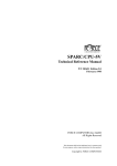
FIGURE 1.
Introduction
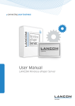
Block Diagram of the SPARC CPU-5TE
SBus Slot
F
R
O
N
T
P
A
N
E
L
8-bit
local bus BOOT
Flash
USER
Flash
Keys
Display
Rotary
LEDs
S4
FPGA
SBus
Ethernet#2 (AUI)*
SLAVIO
Two Serial I/O
Floppy
SCSI#1
Ethernet#2 TP
MicroSPARC
II
RTC/
NVRAM
Keyboard/Mouse
Ethernet#1 TP
8,16,32,64 Mbyte DRAM
(each Module)
SBus
SBus Slot
0 Ohm
TP
MACIO
#1
MACIO
#2
V
M
E
b
u
s
SCSI#2*
Switch Matrix
Keyboard/Mouse
Two Serial I/O
Centronics*
SCSI#1
Ethernet#1 (AUI)
TP
* The Ethernet#2, SCSI#2 and Centronics devices are only available with the 5-row P2 Connector. However,
the SCSI#2 is available on the 3-row P2 Connector through the use of a switch matrix instead of the floppy interface.
1.4
Board Components
As is shown in the above diagram, the microSPARC-II chip interfaces directly to a 64-bit wide
DRAM on the one side and to the SBus on the other side. The SPARC CPU-5TE is available
with 16, or 64 Mbytes of DRAM modules (MEM-5). The shared DRAM is 64-bit wide with 2
bit parity.
The SPARC CPU-5TE utilizes the Sun S4-VME chip to provide a complete 32-bit VMEbus
interface. Using SBus modules, the board becomes a VMEbus two-slot solution.
The SCSI#1, the Ethernet#1, and the parallal port are realized via the NCR89C100 (MACIO
#1). The SCSI#2 and the Ethernet#2 are realized via the NCR89C100 (MACIO #2).
The floppy disk interface, two serial I/O ports, the keyboard/mouse interface are provided by
the NCR89C105 chip (SLAVIO), which additionally controls the boot EPROM, the RTC and
NVRAM, and a user EPROM via its 8-bit expansion port.
FORCE COMPUTERS
Page 3
Introduction
1.5
SPARC CPU-5TE Technical Reference Manual
Specifications
Below is a table outlining the specifications of the SPARC CPU-5TE board.
Table 1: Specifications of the SPARC CPU-5TE
Page 4
Processor
Clock Frequency
SPECint92
SPECfp92
MIPS
MFLOPS
microSPARC-II
85 MHz
64.0
54.6
112.5
14.9
Memory Management Unit
SPARC Reference MMU
Data/Instruction Cache
8 Kbyte/16 Kbyte
Shared Main Memory
8, or 64 Mbyte DRAM
Upgradable to 128 Mbyte
SBus Slots
2, mechanically compatible to CPU-2CE,
CPU-3CE and CPU-5CE
SCSI#1 with DMA to SBus
NCR89C100 (MACIO #1)
10 Mbytes/sec
53C90A superset
I/O on front panel and P2
Ethernet#1 with DMA to SBus
NCR89C100 (MACIO #1)
10 Mbits/sec
AM7990 compatible
I/O on front panel as Twisted Pair and on
P2 as AUI
Parallel port with DMA to SBus
NCR89C100 (MACIO #1)
3.4 Mbytes/sec
Centronics compatible
Uni- or bidirectional
I/O on 5-row P2 connector
SCSI#2 with DMA to SBus
NCR89C100 (MACIO #2)
10 Mbytes/sec
53C90A superset
I/O on on 3-row and 5-row P2 Connector
I/O on P2 via switch matrix (instead of
Floppy Interface)
Ethernet#2 with DMA to SBus
NCR89C100 (MACIO #2)
10 Mbits/sec
AM7990 compatible
I/O on front panel as Twisted Pair and on
5-row P2 connector as AUI
FORCE COMPUTERS
SPARC CPU-5TE Technical Reference Manual
Introduction
Table 1: Specifications of the SPARC CPU-5TE (cont.)
Floppy Disk Interface
NCR89C105
250, 300, 500 Kbytes/sec and 1 Mbytes/sec
82077AA-1 compatible
I/O on P2 via switch matrix
Serial I/O
NCR89C105
Two ports with RS-232 configuration,
8530 compatible
I/O on front panel or P2
Keyboard/Mouse Port
Sun compatible, on front panel or P2
Counters/Timers
Two 22-bit, programmable
Boot Flash Memory
512 Kbyte (1 Mbyte Option)
On-board programmable
Hardware write protection
User Flash Memory
8 Mbyte (optional)
On-board programmable
Hardware write protection
RTC/NVRAM/Battery
Usable Memory
M48T08
8 Kbyte
VMEbus Interface
32-bit master/slave, IEEE-1014
Additional Features
Reset and Abort switches
4 Status LEDs on the front panel
HEX display on the front panel
Watchdog timer
Firmware
OpenBoot with diagnostics
Power consumption
+5V
5.2 A
(No SBus Module installed)
+12V
0.7A
-12V
0.2A
Environmental Conditions
Temperature (Operating)
Temperature (Storage)
Humidity
Board Size
FORCE COMPUTERS
0ο C to +50ο C
-40ο C to +85ο C
0% to 95% noncondensing
Single Slot 6U VMEbus
160.00 x 233.35 mm
6.29 x 9.18 inches
Page 5
Introduction
1.6
SPARC CPU-5TE Technical Reference Manual
Product Nomenclature
FORCE COMPUTERS’ SPARC CPU-5TE is available in several memory and speed options.
Consult your local sales representative to confirm availability of specific combinations.
The table below explains the product nomenclature.
Table 2: Product Nomenclature
1.6.1
CPU-5TE/16-85-0
85 MHz microSPARC-II CPU board with 16-Mbyte DRAM
memory module, 1 free memory expansion slot, dual SCSI-2,
dual Ethernet, floppy disk, keyboard/mouse port, 2 serial I/O
prots, 32-bit VMEbus interface, 2 SBus slots, OpenBoot firmware.
Installation guide included.
CPU-5TE/64-85-0
Same as above, except 64 Mbyte DRAM.
MEM-5/16
16 Mbyte mezzanine memory module for use on the SPARC
CPU-5TE.
MEM-5/64
64 Mbyte mezzanine memory module for use on the SPARC
CPU-5TE.
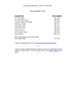
Ordering Information
The next page contains a list of the product names and their descriptions.
Page 6
FORCE COMPUTERS
SPARC CPU-5TE Technical Reference Manual
Introduction
Table 3: Ordering Information
Catalog Name
Product Description
SBus Modules
SBus/GX
Color 2-D and 3-D wireframe graphics accelerator, 1152x900,
8 bits per pixel, single SBus slot.
SBus/TGX
Color 2-D and 3-D wireframe high-performance graphics
accelerator, up to 1152x900, 1 Mbyte VRAM, 8 bits per pixel,
single SBus slot.
SBus/TGX+
Color 2-D and 3-D wire frame high performance graphics
accelerator, up to 1600 x 1280, 4 Mbyte VRAM, 8 bits per
pixel, double buffering, single SBus slot.
SBus/FP
6U Front panel for up to 2 SBus cards.
Accessories
CPU-5TE/TM
SPARC CPU-5TE Technical Reference Manual set
OpenBoot User’s Manual and a Set of Data
including
Sheets.
IOBP-DS
I/O back panel on VMEbus P2 with micro D-sub connector for
one AUI Ethernet, 8-pin mini-circular DIN connector for keyboard/mouse, flat cable connectors for dual SCSI and two serial
I/O interfaces. For use with the CPU-5TE.
Serial-2CE
Adapter cable for one serial port, 26-pin microHD to 25-pin
D-sub. For use with CPU-5TE.
Software
Solaris 2.x/CPU-5TE
Solaris 2.x package with Desktop Right-To-Use license, VMEbus driver on tape.
Solaris 2.x/OLDS/CPU-5TE
Solaris 2.x package with Desktop Right-To-Use license,
Online: DiskSuite for Solaris 2.x, VMEbus driver on tape.
Solaris 2.x/CPU-5TE/
Client -RTU
Solaris 2.x Desktop Right-To-Use license. Without media.
Solaris 2.x/CPU-5TE/
Server-RTU-up
Solaris 2.x Desktop to Workgroup Server Right-To-Use
upgrade license. Without media.
Solaris 2.x/UM
Solaris 2.x Operating System User’s Manual.
Solaris 1.x/CPU-5TE
Solaris 1.x package with Right-To-Use license, VMEbus driver
on tape.
Solaris 1.x/OLDS/CPU-5TE
Solaris 1.x package with Right-To-Use license, Online:
DiskSuite for Solaris 1.x, VMEbus driver on tape.
FORCE COMPUTERS
Page 7
Introduction
SPARC CPU-5TE Technical Reference Manual
Table 3: Ordering Information (cont.)
Catalog Name
Page 8
Product Description
Solaris 1.x/CPU-5TE/RTU
Solaris 1.x Right-To-Use license. Without media.
Solaris 1.x/CPU-5TE/RTU
Solaris 1.x multiuser Right-To-Use license. Without media.
Solaris 1.x/UM
Solaris 1.x Operating System User Manual.
VxWorks/DEV SPARC
Products
VxWorks development package for SPARC host and target.
VxWorks/BSP CPU-5TE
VxWorks board support package for CPU-5TE
FORCE COMPUTERS
SPARC CPU-5TE Technical Reference Manual
1.7
Introduction
History of the Manual
Below is a description of the publication history of this SPARC CPU-5TE Technical Reference
Manual.
Table 4: History of Manual
Edition No.
Description
Date of Last Change
1
First Print
June 1995
2
VME P2 and IOBP-DS Connector Pinout has
been corrected.
The default switch setting of SW4-1 and the
description of the memory module MEM-5
have been corrected.
Description of the Ethernet address and host
ID has been updated.
The 2 sections Controlling the VMEbus Master and Slave Interface and BusNet Support
have been added.
November 1996
2.1
The diagrams of switch in table 5 “Default
Switch Settings” on page 14 have been corrected.
Table 32, “NCR89C105 Chip Address Map,”
on page 68 has been completed.
Editorial changes have been made.
November 1997
FORCE COMPUTERS
Page 9
Introduction
Page 10
SPARC CPU-5TE Technical Reference Manual
FORCE COMPUTERS
SPARC CPU-5TE
SECTION 2
2.
Installation
INSTALLATION
Introduction
This Installation Section provides guidelines for powering up the SPARC CPU-5TE board.
The Installation Section, which you have in your hand now, appears both as Section 2 of the
SPARC CPU-5TE Technical Reference Manual and as a stand-alone Installation Guide. This
stand-alone Installation Guide is delivered by FORCE COMPUTERS with every board. The
SPARC CPU-5TE Technical Reference Manual provides a comprehensive hardware and
software guide to your board and is intended for those persons who require complete
information.
2.1
Caution
Please read this Installation Section before installing the board. Take a moment to examine the
Table of Contents to see how this documentation is structured. This will be of value to you
when looking for specific information in the future.
CAUTION: Do not plug or remove board under power.
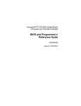
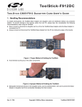
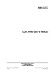
2.2
Location Diagram of the SPARC CPU-5TE Board
A location diagram showing the important components on the CPU-5TE (top view) appears on
the following page. On the page next to it, there is a location diagram of the CPU-5TE (bottom
view) showing the position of five of the on-board switches.
FORCE COMPUTERS
Page 11
Installation
SPARC CPU-5TE
FIGURE 2.
Diagram of the CPU-5TE (Top View)
J 124
SW10
Lower
(#1)
Micro
SPARC-II
Abort
7-Segment
Display
RTC/NVRAM
Reset
Boot Flash
Memory
Upper
(#2)
Status LEDs
SW4
J 125
Rotary
S4-VME
SBus Slot #1 at P3
Memory Module #1
A and B
Serial Port
LCA
Memory Module #2
Keyboard
and
Mouse
SW6
User LEDs
B2, B3, B1
and
B 10, B9, B8
are the sockets for
SCSI #2/Floppy
Switch Matrix
NCR89C105
SW11
B2 B3 B1
SW 7
"SLAVIO"
SCSI #1
Twisted
Pair
Ethernet 2
Twisted
Pair
Ethernet 1
Page 12
"MACIO"
#2
B10 B9 B8
SBus Slot #2 at P4
NCR89C100
NCR89C100
"MACIO"
#1
FORCE COMPUTERS
SPARC CPU-5TE
FIGURE 3.
Installation
Diagram of the CPU-5TE (Bottom View)
SW9
SW8
SW12
SW5
SW13
FORCE COMPUTERS
Page 13
Installation
2.3
SPARC CPU-5TE
Before Powering Up
Before powering up, please make sure that the default switch settings are all set according to
the table below. Check these switch settings before powering up the SPARC CPU-5TE
because the board is configured for power up according to these default settings. For the
position of the switches on the board, please see the diagrams on the previous two pages.
2.3.1
Default Switch Settings
Table 5: Default Switch Settings
Diagram of Switch
Switches
Default
Setting
Function
SWITCH 4
SW4-1
OFF
reserved, must be OFF.
SW4-2
ON
reserved, must be ON.
ON
1
2
SWITCH 5
ON
1
2
3
4
SW5-1
OFF
Test Switch, must be OFF
SW5-2
ON
Test Switch, must be ON
SW5-3
OFF
SCSI Termination for SCSI # 2 on P2
OFF = Enable, ON = Disable
SW5-4
ON
SCSI Termination for SCSI # 1 on P2
OFF = Enable, ON = Disable
SWITCH 6
SW6-1
ON
Reset Key Control
ON=Reset Key enable, OFF=Reset Key disable
SW6-2
ON
Abort Key Control
ON=Abort Key enable, OFF=Abort Key disable
ON
1
2
Page 14
FORCE COMPUTERS
SPARC CPU-5TE
Installation
Table 5: Default Switch Settings (cont.)
Diagram of Switch
Switches
Default
Setting
Function
SWITCH 7
SW7-1
OFF
SCSI#1 termination for Front Panel
OFF = Automatic (When a connector is plugged
into the front panel SCSI connector, then termination is disabled. When no connector is
plugged into the front panel SCSI connector,
then termination is enabled.)
ON = disabled
SW7-2
OFF
Test Switch, must be OFF
ON
1
2
SWITCH 8
ON
1
2
3
4
SW8-1
OFF
Test Switch, must be OFF
SW8-2
ON
TRXC on Front Panel Connector for RS-232
ON=Available, OFF=Not Available
(Serial Port B)
SW8-3
ON
TRXC on Front Panel Connector for RS-232
ON=Available, OFF=Not Available
(Serial Port A)
SW8-4
OFF
TRXC +/- on Front Panel Connector for RS-422
ON=Available, OFF=Not Available
(Serial Port B)
SWITCH 9
SW9-1
ON
CTS on Front Panel Connector for RS-232 or
CTS +/- on Front Panel Connector for RS-422
ON=Available, OFF=Not Available
(Serial Port B)
SW9-2
ON
RTS on Front Panel Connector for RS-232 or
RTS +/- on Front Panel Connector for RS-422
ON=Available, OFF=Not Available
(Serial Port B)
SW9-3
ON
RTS on Front Panel Connector for RS-232 or
RTS +/- on Front Panel Connector for RS-422
ON=Available, OFF=Not Available
(Serial Port A)
SW9-4
OFF
TRXC +/- on Front Panel Connector for RS-422
ON=Available, OFF=Not Available
(Serial Port A)
ON
1
2
3
4
FORCE COMPUTERS
Page 15
Installation
SPARC CPU-5TE
Table 5: Default Switch Settings (cont.)
Diagram of Switch
Switches
Default
Setting
Function
SWITCH 10
SW10-1
OFF
ON
VMEbus Slot-1 Device
ON = Slot-1 Device
OFF = Not Slot-1 Device OR Automatic Slot-1
Device Recognition (This depends on SW10-2
setting, If SW10-2 is Off, the Not Slot-1 Device
is selected and if SW10-2 is ON, the Automatic
Slot-1 Device Recognition is selected.
See also “VME Slot-1 Device (Special Considerations)” on page 19.
1
2
SW10-2
ON
VMEbus Slot-1 Device
ON = Automatic Slot-1 Device Recognition
OFF = Not Slot-1 Device
(If SW10-1 is On, this switch is "don’t care")
See also “VME Slot-1 Device (Special Considerations)” on page 19.
SWITCH 11
SW11-1
ON
SYSRESET received from VMEbus
ON = VMEbus SYSRESET generates on-board
RESET
OFF = VMEbus SYSRESET does not
generate on-board RESET
SW11-2
ON
VMEbus SYSRESET Generation
ON = SYSRESET is driven to VMEbus if board
is Slot-1 Device or during power-up reset
OFF = SYSRESET is not driven to VMEbus
ON
1
2
SWITCH 12
SW12-1
OFF
RTXC +/- on Front Panel Connector for RS-422
ON=Available, OFF=Not Available
(Serial Port B)
SW12-2
ON
CTS on Front Panel Connector for RS-232 or
CTS +/- on Front Panel Connector for RS-422
ON=Available, OFF=Not Available
(Serial Port A)
SW12-3
OFF
RTXC +/- on Front Panel Connector for RS-422
ON=Available, OFF=Not Available
(Serial Port A)
SW12-4
OFF
Test Switch, must be OFF
ON
1
2
3
4
Page 16
FORCE COMPUTERS
SPARC CPU-5TE
Installation
Table 5: Default Switch Settings (cont.)
Diagram of Switch
Switches
Default
Setting
Function
SWITCH 13
ON
1
2
3
4
SW13-1
OFF
User Flash EPROM write protection
ON = disable, OFF = enable
SW13-2
OFF
Boot Flash EPROM write protection
ON = disable, OFF = enable
SW13-3
OFF/ON
No function
SW13-4
OFF/ON
No function
CAUTION: To avoid damaging the serial ports, please consider the following regarding
Switch 8, Switch 9 and Switch 12. Do not set the switches (SW8-3 and SW12-4), or (SW9-4
and SW9-3), or (SW12-2 and SW12-3) to ON at the same time and do not set the switches
(SW8-2 and SW8-1), or (SW8-4 and SW9-2), or (SW9-1 and SW12-1) to ON at the same
time!
FORCE COMPUTERS
Page 17
Installation
2.3.2
SPARC CPU-5TE
Memory Module MEM-5
It is necessary to install the memory module on the board before powering up. For instructions
on installing the MEM-5, please see the document How to Install MEM-5.
Memory Module # 1 must be installed for power up because it holds configuration
information for booting the board. Memory module # 2 is optional for increasing memory
capacity. For the location of the memory module connectors on the board, please see
“Diagram of the CPU-5TE (Top View)” on page 12.
Page 18
FORCE COMPUTERS
SPARC CPU-5TE
2.4
Installation
Powering Up
The initial power up can easily be done by connecting a terminal to ttya (serial port A). The
advantage of using a terminal is that no frame buffer, monitor, or keyboard is used for initial
power up, which facilitates a simple startup.
Please see the chapter “Boot the System” on page 25 for more detailed information on booting
the system.
2.4.1
VME Slot-1 Device (Special Considerations)
The SPARC CPU-5TE can be plugged into any VMEbus slot; however, the default
configuration automatically detects that the board is a VME slot-1 device, which functions as
VME system controller. To configure your CPU-5TE so it is not a VME slot-1 device, the
default configuration must be changed so that SW10-2 is OFF.
An additional consideration concerning the VMEbus slot-1 selection is shown in the following
table. It is important to see that Switch 10-1 and Switch 10-2 function together.
Table 6: VME Slot-1 Device Switch Setting
SW10-1
SW10-2
Function
On
Don’t Care
(either On or
Off)
Off
On
Automatic Slot-1 Device Detection (See Note below)
Off
Off
Not Slot-1 Device
Default
Slot-1 Device
*
NOTE: When the automatic slot-1 device detection method is used to enable VMEbus slot-1
device functionality, the VME SYSCLOCK is not driven during RESET. Normally, this
presents no problem. However, in the case that a VMEbus participant needs this SYSCLOCK
signal, you must use only the slot-1 device method, and not the automatic slot-1 device
detection method, to enable the VMEbus slot-1 device functionality. By setting SW10-1 to On,
the slot-1 device method, and not automatic slot-1 detection, is selected.
CAUTION: Before installing the SPARC CPU-5TE in a miniforce chassis, please first disable
the VMEbus System Controller function by setting switch SW10-2 to OFF.
FORCE COMPUTERS
Page 19
Installation
SPARC CPU-5TE
2.4.2
VMEbus SYSRESET
2.4.2.1
SYSRESET Input
A SYSRESET received from VMEbus generates an on-board RESET if switch SW11-1 is ON
(default setting). When SW11-1 is OFF, the SYSRESET received from the VMEbus does not
generate an on-board RESET.
2.4.2.2
SYSRESET Output
There are several possible ways for the CPU-5TE to generate a SYSRESET signal to the
VMEbus. One way is when the CPU-5TE is a VMEbus slot-1 device and an on-board local
SBus reset occurs, then the CPU-5TE generates the SYSRESET signal to the VMEbus. A
second way for the SYSRESET signal to be generated is by power-up reset. Power-up reset
occurs by switching on the power. Power-up Reset also occurs when the power monitor
detects power fail or the front panel reset key is toggled.
This SYSRESET signal can be disabled by setting the switch SW11-2 to OFF.
2.4.3
Serial Ports
By default, both serial ports are configured as RS-232 interfaces. The chapter “Default Switch
Settings” on page 14 shows the necessary switch settings for RS-232 operation.
Page 20
FORCE COMPUTERS
SPARC CPU-5TE
2.4.4
Installation
RESET and ABORT Key Enable
To enable the RESET and the ABORT functions on the front panel, set switches SW6-1
(RESET) and SW6-2 (ABORT) to ON. This is the default setting.
2.4.5
Front Panel SCSI#1 Termination
Please note how the SCSI#1 termination works on the front panel. Termination for the SCSI#1
interface is disabled when SW7-1 is ON. When switch SW7-1 is OFF, the termination is set
to automatic termination mode. Automatic termination mode means the respective termination
is disabled when you connect a standard SCSI cable to the connector.
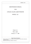
2.4.6
P2 SCSI Termination
Termination for the P2 SCSI#1 is disabled when SW5-4 is ON, and this is the default setting.
Termination for the P2 SCSI#2 is enabled when SW5-3 is OFF, and this is the default setting.
FIGURE 4.
F
R
O
N
T
P
A
N
E
L
SCSI Termination
SW5-3 controls SCSI#2 termination on P2
OFF = Enable
ON = Disabled
MACIO
#2
Termination
SW7-1 controls SCSI#1 termination for Front Panel
OFF = Automatic
ON = Disabled
MACIO
#1
Termination
SCSI#1
FORCE COMPUTERS
V
M
E
B
u
s
SCSI#2
P
2
C
o
n
SW5-4 controls SCSI#1 n
termination on P2
e
OFF = Enable
c
ON = Disabled
t
o
Termination
r
SCSI#1
Page 21
Installation
2.4.7
SPARC CPU-5TE
Boot Flash EPROM Write Protection
Both Boot Flash EPROMs are write protected via the switch SW13-2. When SW13-2 is OFF,
the devices are write protected, and this is the default setting.
2.4.8
User Flash EPROM Write Protection
The optional User Flash EPROMs are write protected via SW13-1. When SW13-1 is OFF, the
User Flash EPROMs are write protected, and this is the default setting.
2.4.9
Reserved Switches
SW5-1, SW5-2, SW7-2, SW8-1, SW10-1 and SW12-4 are reserved for test purposes. SW5-1,
SW7-2, SW8-1, SW10-1 and SW12-4 should always be OFF. SW5-2 should always be ON.
Page 22
FORCE COMPUTERS
SPARC CPU-5TE
2.4.10
Installation
Floppy Interface or SCSI#2 Availability on P2
It is important to understand that the availability of both the floppy and SCSI#2 devices at the
same time is dependent upon the availability of a 5-row P2 connector. When using a 3-row P2
connector, you have the choice of either the floppy or the SCSI#2 on P2. The following
describes how to configure the board for floppy or SCSI#2.
Via a 24-pin configuration switch matrix, it is possible for either the floppy interface or the
SCSI#2 to be available on the VME P2 connector on row C. The default setting enables the
floppy interface via the VME P2 connector, with the configuration switch matrix plugged into
B2/B3 and B10/B9. This means, of course, that by default the SCSI#2 is not available via the
VMEbus P2 connector on row C.
To enable the SCSC#2 via the VME P2 connector, plug the configuration switch matrix in
sockets B3/B1 and B9/B8.
FIGURE 5.
Floppy or SCSI #2 Availability on P2
B2 B3 B1
This 3-piece configuration
switch matrix is used for
choosing either the floppy
interface or SCSI#2.
Plug the interface into
sockets B2/B3 and B10/B9
for the floppy interface.
Or
Plug the interface into
sockets B3/B1 and B9/B8
for the SCSI#2 interface.
B10 B9 B8
CAUTION: If you use an IOBP-DS, the switch matrix must be located on B3/B1 and B9/B8
in order to route SCSI #2 to P2 row C. If you use an IOBP-10, the switch matrix must be
located on B2/B3 and B10/B9 in order to route the floppy interface to P2 row C.
FORCE COMPUTERS
Page 23
Installation
2.4.11
SPARC CPU-5TE
Network Interface Selection (NIS) for Ethernet
It is important to understand that the Ethernet is selected either via the twisted pair connector
or the AUI (Attachment Unit Interface). When you boot your system and a connection exists
with an AUI network, then the AUI is automatically selected. In other words, when you have
a successful connection with a network, the AUI is used. When you have no connection with
the network, then the twisted pair is selected. This is valid for both Ethernet #1 and
Ethernet #2. The Ethernet#1 channel and the Ethernet#2 channel function independently of
each other. For both Ethernet interfaces there is one Ethernet address. This means that you
don’t have to connect both interfaces to one physical cable.
2.4.12
Parallel Port
The availability of the parallel port is dependent upon the availability of a 5-row P2 connector.
When using a 3-row P2 connector, parallel port is not available.
Page 24
FORCE COMPUTERS
SPARC CPU-5TE
2.5
Installation
OpenBoot Firmware
This chapter describes the use of OpenBoot firmware. Specifically, you will read how to
perform the following tasks.
•
•
•
•
•
Boot the System
Run Diagnostics
Display System Information
Reset the System
OpenBoot Help
For detailed information concerning OpenBoot, please see the OPEN BOOT PROM 2.0
MANUAL SET. This manual is included in the SPARC CPU-5TE Technical Reference Manual
Set.
2.5.1
Boot the System
The most important function of OpenBoot firmware is booting the system. Booting is the
process of loading and executing a stand-alone program such as the operating system. After it
is powered on, the system usually boots automatically after it has passed the Power On SelfTest
(POST). This occurs without user intervention.
If necessary, you can explicitly initiate the boot process from the OpenBoot command
interpreter. Automatic booting uses the default boot device specified in nonvolatile RAM
(NVRAM); user initiated booting uses either the default boot device or one specified by the
user.
To boot the system from the default boot device, type the following command at the Forth
Monitor prompt.
ok boot
or, if you are at the Restricted Monitor Prompt, you have to type the following:
>b
FORCE COMPUTERS
Page 25
Installation
SPARC CPU-5TE
The boot command has the following format:
boot [device-specifier] [filename] [-ah]
The optional parameters are described as follows.
[device-specifier]
The name (full path or alias) of the boot device. Typical values
are cdrom, disk, floppy, net or tape.
[filename]
The name of the program to be booted. filename is relative to the
root of the selected device. If no filename is specified, the boot
command uses the value of boot-file NVRAM parameter. The
NVRAM parameters used for booting are described in the
following chapter.
[-a]
-a prompt interactively for the device and name of the boot file.
[-h]
-h halt after loading the program.
NOTE: These options are specific to the operating system and may differ from system to
system.
To explicitly boot from the internal disk, type:
ok boot disk
or at the Restricted Monitor prompt:
>b
Page 26
disk
FORCE COMPUTERS
SPARC CPU-5TE
Installation
To retrieve a list of all device alias definitions, type devalias at the Forth Monitor command
prompt. The following table lists some typical device aliases:
Table 7: Device Alias Definitions
Alias
Boot Path
Description
disk
/iommu/sbus/espdma/esp/sd@3,0
Default disk (1st internal) SCSI-ID 3
disk3
/iommu/sbus/espdma/esp/sd@3,0
First internal disk SCSI-ID 3
disk2
/iommu/sbus/espdma/esp/sd@2,0
Additional internal disk SCSI-ID 2
disk1
/iommu/sbus/espdma/esp/sd@1,0
External disk SCSI-ID 1
disk0
/iommu/sbus/espdma/esp/sd@0,0
External disk SCSI-ID 0
tape
/iommu/sbus/espdma/esp/st@4,0
First tape drive SCSI-ID 4
tape0
/iommu/sbus/espdma/esp/st@4,0
First tape drive SCSI-ID 4
tape1
/iommu/sbus/espdma/esp/st@5,0
Second tape drive SCSI-ID 5
cdrom
/iommu/sbus/espdma/esp/sd@6,0:d
CD-ROM partition d, SCSI-ID 6
net
/iommu/sbus/ledma/le
Ethernet
floppy
/obio/SUNW,fdtwo
Floppy drive
FORCE COMPUTERS
Page 27
Installation
2.5.2
SPARC CPU-5TE
NVRAM Boot Parameters
The OpenBoot firmware holds configuration parameters in NVRAM. At the Forth Monitor
prompt, type printenv to see a list of all available configuration parameters. The OpenBoot
command setenv may be used to set these parameters.
setenv [configuration parameter] [value]
This information refers only to those configuration parameters which are involved in the boot
process. The following table lists these parameters.
Table 8: Setting Configuration Parameters
Parameter
Default Value
Description
auto-boot?
true
If true, boot automatically after power on or reset
boot-device
disk
Device from which to boot
boot-file
empty string
File to boot
diag-switch?
false
If true, run in diagnostic mode
diag-device
net
Device from which to boot in diagnostic mode
diag-file
empty string
File to boot in diagnostic mode
When booting an operating system or another stand-alone program, and neither a boot device
nor a filename is supplied, the boot command of the Forth Monitor takes the omitted values
from the NVRAM configuration parameters. If the parameter diag-switch? is false, bootdevice and boot-file are used. Otherwise, the OpenBoot firmware uses diag-device and diagfile for booting.
For a detailed description of all NVRAM configuration parameters, please refer to the OPEN
BOOT PROM 2.0 MANUAL SET.
Page 28
FORCE COMPUTERS
SPARC CPU-5TE
2.5.3
Installation
Diagnostics
At power on or after reset, the OpenBoot firmware executes POST. If the NVRAM
configuration parameter diag-switch? is true for each test, a message is displayed on a terminal
connected to the first serial port. In case the system is not working correctly, error messages
indicating the problem are displayed. After POST, the OpenBoot firmware boots an operating
system or enters the Forth Monitor if the NVRAM configuration parameter auto-boot? is false.
The Forth Monitor includes several diagnostic routines. These on-board tests let you check
devices such as network controller, SCSI devices, floppy disk system, memory, clock and
installed SBus cards. User installed devices can be tested if their firmware includes a selftest
routine.
The table below lists several diagnostic routines.
Table 9: Diagnostic Routines
Command
Description
probe-scsi
Identify devices connected to the on-board SCSI bus
probe-scsi-all [device-path]
Perform probe-scsi on all SCSI buses installed in the
system below the specified device tree node. (If
device-path is omitted, the root node is used.)
test device-specifier
Execute the specified device’s selftest method.
device-specifier may be a device path name or a
device alias.
For example:
test net - test network connection
test /memory - test number of megabytes specified in
the selftest-#megs NVRAM parameter or test all of
memory if diag-switch? is true
test-all [device-specifier]
Test all devices (that have a built-in selftest method)
below the specified device tree node. (If device-path
is omitted, the root node is used.)
watch-clock
Monitor the clock function
watch-net
Monitor network connection
To check the on-board SCSI bus for connected devices, type:
ok probe-scsi
Target 3
Unit 0 Disk MICROP 1684-07MB1036511AS0C1684
ok
FORCE COMPUTERS
Page 29
Installation
SPARC CPU-5TE
To test all the SCSI buses installed in the system, type:
ok probe-scsi-all
/iommu@0,10000000/sbus@0,10001000/esp@2,100000
Target 6
Unit 0 Disk Removable Read Only Device SONY CD-ROM CDU-8012 3.1a
/iommu@0,10000000/sbus@0,10001000/espdma@4,8400000/esp@4,8800000
Target 3
Unit 0 Disk MICROP 1684-07MB1036511AS0C1684
ok
The actual response depends on the devices on the SCSI buses.
To test a single installed device, type:
ok test
device-specifier
This executes the device method name selftest of the specified device node.
device-specifier may be a device path name or a device alias as described in Table 7, “Device
Alias Definitions,” on page 27. The response depends on the selftest of the device node.
To test a group of installed devices, type:
ok test-all
All devices below the root node of the device tree are tested. The response depends on the
devices that have a selftest routine. If a device specifier option is supplied at the command line,
all devices below the specified device tree node are tested.
When you use the memory testing routine, the system tests the number of megabytes of
memory specified in the NVRAM configuration parameter selftest-#megs. If the NVRAM
configuration parameter diag-switch? is true, all memory is tested.
ok test /memory
testing 32 megs of memory at addr 0 27
ok
The command test-memory is equivalent to test /memory. In the example above, the first
number (0) is the base address of the memory bank to be tested, the second number (27) is the
number of megabytes remaining. If the CPU board is working correctly, the memory is erased
Page 30
FORCE COMPUTERS
SPARC CPU-5TE
Installation
and tested and you will receive the ok prompt. If the PROM or the on-board memory is not
working, you receive one of a number of possible error messages indicating the problem.
To test the clock function, type:
ok watch-clock
Watching the ‘seconds’ register of the real time clock chip.
It should be ‘ticking’ once a second.
Type any key to stop.
22
ok
The system responds by incrementing a number once a second. Press any key to stop the test.
To monitor the network connection, type:
ok watch-net
Using AUI Ethernet Interface
Lance register test -- succeeded.
Internal loopback test -- succeeded.
External loopback test -- succeeded.
Looking for Ethernet packets.
‘.’ is a good packet. ‘X’ is a bad packet.
Type any key to stop.
...........X...........................X..............
ok
The system monitors the network traffic, displaying “.” each time it receives a valid packet and
displaying “X” each time it receives a packet with an error that can be detected by the network
hardware interface.
FORCE COMPUTERS
Page 31
Installation
SPARC CPU-5TE
2.5.4
Display System Information
The Forth Monitor provides several commands to display system information. These
commands let you display the system banner, the Ethernet address for the Ethernet controller,
the contents of the ID PROM, and the version number of the OpenBoot firmware.
The ID PROM contains information specific to each individual machine, including the serial
number, date of manufacture, and assigned Ethernet address.
The following table lists these commands.
Table 10: Commands to Display System Information
Command
Description
banner
Display system banner.
show-sbus
Display list of installed and probed SBus
devices.
.enet-addr
Display current Ethernet address.
.idprom
Display ID PROM contents, formatted.
.traps
Display a list of SPARC trap types.
.version
Display version and date of the Boot PROM.
show-devs
Display a list of all device tree nodes.
devalias
Display a list of all device aliases.
Page 32
FORCE COMPUTERS
SPARC CPU-5TE
2.5.5
Installation
Reset the System
If your system needs to be reset, you either press the reset button on the front panel or, if you
are in the Forth Monitor, type reset on the command line.
ok reset
The system immediately begins executing the Power On SelfTest (POST) and initialization
procedures. Once the POST finishes, the system either boots automatically or enters the Forth
Monitor, just as it would have done after a power on cycle.
2.5.6
OpenBoot Help
The Forth Monitor contains an on-line help. To get this, type:
ok help
Enter ‘help command-name’ or ‘help category-name’ for more help
(Use ONLY the first word of a category description)
Examples: help select -or- help line
Main categories are:
File download and boot
Resume execution
Diag (diagnostic routines)
Power on reset
>-prompt
Floppy eject
Select I/O devices
Ethernet
System and boot configuration parameters
Line editor
Tools (memory, numbers, new commands, loops)
Assembly debugging (breakpoints, registers, disassembly, symbolic)
Sync (synchronize disk data)
Nvramrc (making new commands permanent)
ok
A list of all available help categories is displayed. These categories may also contain
subcategories. To get help for special forth words or subcategories just type help [name]. An
example is shown on the next page.
FORCE COMPUTERS
Page 33
Installation
SPARC CPU-5TE
An example of how to get help for special forth words or subcategories.
ok help tools
Category: Tools (memory, numbers, new commands, loops)
Sub-categories are:
Memory access
Arithmetic
Radix (number base conversions)
Numeric output
Defining new commands
Repeated loops
ok
ok help memory
Category: Memory access
dump ( addr length -- ) display memory at addr for length bytes
fill ( addr length byte -- ) fill memory starting at addr with byte
move ( src dest length -- ) copy length bytes from src to dest address
map? ( vaddr -- ) show memory map information for the virtual address
l? ( addr -- ) display the 32-bit number from location addr
w? ( addr -- ) display the 16-bit number from location addr
c? ( addr -- ) display the 8-bit number from location addr
l@ ( addr -- n ) place on the stack the 32-bit data at location addr
w@ ( addr -- n ) place on the stack the 16-bit data at location addr
c@ ( addr -- n ) place on the stack the 8-bit data at location addr
l! ( n addr -- ) store the 32-bit value n at location addr
w! ( n addr -- ) store the 16-bit value n at location addr
c! ( n addr -- ) store the 8-bit value n at location addr
ok
The on-line help shows you the forth word, the parameter stack before and after execution of
the forth word ( before -- after), and a short description.
The on-line help of the Forth Monitor is located in the boot PROM, so there is not an on-line
help for all forth words.
Page 34
FORCE COMPUTERS
SPARC CPU-5TE
2.6
Installation
Front Panel
FIGURE 6.
Diagram of the Front Panel
SPARC
CPU-5TE
RESET
ABORT
D
I
A
G
M
O
D
E
RUN BM
SYS UL
K
B
D
S
E
R
I
A
L
A
+
B
S
C
S
I
ETH-TP 2
ETH-TP 1
FORCE COMPUTERS
Page 35
Installation
2.6.1
SPARC CPU-5TE
Features of the Front Panel
•
Reset and Abort key
•
Status LEDs on the front panel
•
Hex display on the front panel
These features are described in detail in Section 3 of the SPARC CPU-5TE Technical
Reference Manual.
2.7.
Front Panel Layout
Device
Page 36
Function
Name
Switch
Reset
RESET
Switch
Abort
ABORT
HEX. Display
Diagnostic
DIAG
Rotary Switch
Diagnostic
MODE
LED/LED
Run-Halt
VME BM-SYSFAIL
RUN
BM
LED/LED
Slavio SYS LED
User LED
SYS
UL
Mini DIN Connector
Keyboard/Mouse
KBD
Serial Connector
Serial Interface A and B
SERIAL A+B
SCSI Connector
SCSI Interface
SCSI
RJ45 Connector
Ethernet Interface
ETH 2
RJ45 Connector
Ethernet Interface
ETH 1
FORCE COMPUTERS
SPARC CPU-5TE
2.8
Installation
SPARC CPU-5TE Connectors
The connectors on the SPARC CPU-5TE are listed in the following table.
Table 11: SPARC CPU-5TE Connectors
Function
Location
Type
Manufacturer Part
Number
Ethernet # 1
(Twisted Pair)
Front Panel
RJ-45
AMP 555131-1
Ethernet # 2
(Twisted Pair)
Front Panel
RJ-45
AMP 555131-1
Serial Port A + B
Front Panel
26-pin Fine Pitch
AMP 749831-2
SCSI
Front Panel
50-pin Fine Pitch
AMP 749831-5
Keyboard/Mouse
Front Panel
8-pin Mini DIN
AMP 749232-1
SBus Slot2
(SBus Slave Select 1)
P3
96-pin SMD
FUJITSU FCN-234J096-G/V
SBus Slot3
(SBus Slave Select 2)
P4
96-pin SMD
FUJITSU FCN-234J096-G/V
VMEbus P1
P1
96-pin VGA
Various
VMEbus P2
P2
96-pin VGA
Various
The following pages show the pinouts of the connectors.
FORCE COMPUTERS
Page 37
Installation
2.8.1
SPARC CPU-5TE
Twisted Pair Ethernet Connector Pinout
The following table shows the pinout of the twisted pair Ethernet connector. The pinout for
both of the connectors is identical.
Table 12: Twisted Pair Ethernet Connector Pinout
FIGURE 7.
Pin
Number
Signal
Name
1
TPE0
2
TPE1
3
TPE2
4
N.C.
5
N.C.
6
TPE3
7
N.C.
8
N.C.
Twisted Pair Ethernet
1 2 34 5 6 7 8
RJ45
Page 38
FORCE COMPUTERS
SPARC CPU-5TE
2.8.2
Installation
Serial Port A and B Connector Pinout
The following table is a pinout of the serial port connector. The figure on the next page shows
the serial port connector and location of the pin numbers.
Table 13: Serial Port A and B Connector Pinout
Pin
Signal
Direction
Port
Description
1
none
none
A
Not connected
2
TD
output
A
Transmit Data
3
RD
input
A
Receive Data
4
RTS
output
A
Request To Send
5
CTS
input
A
Clear To Send
6
DSR
input
A
Data Set Ready
7
SG
none
A
Signal Ground
8
DCD
input
A
Data Carrier Detect
9
none
none
Not connected
10
none
none
Not connected
11
SDTR
output
B
Secondary Data Terminal Ready
12
SDCD
input
B
Secondary Data Carrier Detect
13
SCTS
input
B
Secondary Clear To Send
14
STD
output
B
Secondary Transmit Data
15
TC
input
A
Transmit Clock: DCE Source
16
SRD
input
B
Secondary Receive Data
17
RC
input
A
Receive Clock
18
STC
input
B
Secondary Transmit Clock
19
SRTS
output
B
Secondary Request To Send
20
DTR
output
A
Data Terminal Ready
21
SDSR
input
B
Secondary Data Terminal Ready
22
SRC
input
B
Secondary Receive Clock
23
SSG
none
B
Secondary Signal Ground
24
TC
output
A
Transmit Clock: DTE Source
25
STC
output
B
Transmit Clock: DTE Source
26
none
none
Not connected
FORCE COMPUTERS
Page 39
Installation
FIGURE 8.
SPARC CPU-5TE
Serial Ports A and B Connector Pinout
13
26
Page 40
1
14
FORCE COMPUTERS
SPARC CPU-5TE
2.8.3
Installation
Keyboard/Mouse Connector Pinout
The keyboard and mouse port is available on the front panel via a Mini DIN connector.
Table 14: Keyboard/Mouse Connector Pinout
Pin
FIGURE 9.
Function
1
GND
2
GND
3
+5VDC
4
Mouse In
5
Keyboard Out
6
Keyboard In
7
Mouse Out
8
+5VDC
Keyboard/Mouse Connector
8 7 6
5
4
2
FORCE COMPUTERS
3
1
Page 41
Installation
2.8.4
SPARC CPU-5TE
VME P2 Connector Pinout
The SCSI#2 interface is an alternative to the FDC interface. The signals for rows Z and D are
only available on the 5-row P2 Connector.
Table 15: VME P2 Connector Pinout
Pin #
Signal Row Z
Signal Row A
Signal Row C
(FDC signals)
1
2
3
4
5
6
7
8
9
10
11
12
13
14
15
16
17
18
19
20
21
22
CENTR DS
GND
CENTR D0
GND
CENTR D1
GND
CENTR D2
GND
CENTR D3
GND
CENTR D4
GND
CENTR D5
GND
CENTR D6
GND
CENTR D7
GND
CENTR ACK
GND
CENTR BSY
GND
SCSI#1-D0
SCSI#1-D1
SCSI#1-D2
SCSI#1-D3
SCSI#1-D4
SCSI#1-D5
SCSI#1-D6
SCSI#1-D7
SCSI#1-DP
GND
GND
GND
TERMPWR#1
GND
GND
SCSI#1-ATTN
GND
SCSI#1-BSY
SCSI#1-ACK
SCSI#1-RST
SCSI#1-MSG
SCSI#1-SEL
FPY DENSEL
FPY DENSENS
N.C.
FPY INDEX
FPY DRVSEL
N.C.
N.C.
FPY MOTEN
FPY DIR
FPY STEP
FPY WRDATA
FPY WRGATE
FPY TRACK0
FPY WRPROT
FPY RDDATA
FPY HEADSEL
FPY DISKCHG
FPY EJECT
+12VDC
GND
GND
ETH REC+
SCSI#2-D0
SCSI#2-D1
SCSI#2-D2
SCSI#2-D3
SCSI#2-D4
SCSI#2-D5
SCSI#2-D6
SCSI#2-D7
SCSI#2-DP
SCSI#2-ATTN
SCSI#2-BSY
SCSI#2-ACK
SCSI#2-RST
SCSI#2-MSG
SCSI#2-SEL
SCSI#2-CD
SCSI#2-REQ
SCSI#2-IO
ETH#1_POW
TERMPWR#2
GND
ETH#1_REC+
23
24
25
26
27
28
29
30
31
32
CENTR PE
GND
CENTR AF
GND
CENTR INIT
GND
CENTR ERR
GND
CENTR SLCT
GND
SCSI#1-CD
SCSI#1-REQ
SCSI#1-IO
MOUSEIN
TXD_KBD
RXD_KBD
TXD_A
RXD_A
DTR_A
DCD_A
ETH#1_RECETH#1_TRA+
ETH#1_TRAETH#1_COL+
ETH#1_COLGND
TXD_B
RXD_B
DTR_B
DCD_B
ETH#1_RECETH#1_TRA+
ETH#1_TRAETH#1_COL+
ETH#1_COLGND
TXD_B
RXD_B
DTR_B
DCD_B
Page 42
Signal Row C
(SCSI#2 signals)
Signal Row D
NC
NC
SCSI#2-D0
SCSI#2-D1
SCSI#2-D2
SCSI#2-D3
SCSI#2-D4
SCSI#2-D5
SCSI#2-D6
SCSI#2-D7
SCSI#2-DP
TERMPWR#2
SCSI#2-ATTN
SCSI#2-BSY
SCSI#2-ACK
SCSI#2-RST
SCSI#2-MSG
SCSI#2-SEL
SCSI#2-CD
SCSI#2-REQ
SCSI#2-IO
CENTR
SLCTIN
MOUSEOUT
ETH#2_POW
ETH#2_REC+
ETH#2_RECETH#2_TRA+
ETH#2_TRAETH#2_COL+
ETH#2_COLNC
NC
FORCE COMPUTERS
SPARC CPU-5TE
2.8.5
Installation
The IOBP-10 Connectors
The IOBP-10 is an I/O back panel on VMEbus P2 with flat cable connectors for SCSI, serial
I/O, Centronics/floppy interface, and a micro D-Sub connector for the Ethernet#1 interface.
The Centronics interface on the IOBP-10 is not supported by the CPU-5TE. This back panel
can be plugged into the VMEbus P2 connector. The diagram below shows all the connectors.
The IOBP-10 back panel and the IOBP-DS are especially designed for the SPARC CPU-5TE.
Do not use any other I/O back panels on the SPARC CPU-5TE, for example, the IOBP-1.
2.8.5.1
Jumper Setting for IOBP-10
Please make sure that the configuration switch matrix is plugged into sockets B2 / B3 and
B10 / B9, that is, the configuration for floppy interface on P2. This is described in chapter
“Floppy Interface or SCSI#2 Availability on P2” on page 23.
FIGURE 10.
The IOBP-10
ABC
1
2
1
2
1
2
1
1
2
49
50
14
13
33
34
39
40
8 15
32
1 9
The pinouts of the connectors (P1) ... (P6) are shown in the following tables.
CAUTION
This IOBP-10 back panel and the IOBP-DS are especially designed for the SPARC CPU-5TE.
Do not use any other I/O back panels on the SPARC CPU-5TE, for example, the IOBP-1.
FORCE COMPUTERS
Page 43
Installation
SPARC CPU-5TE
Table 16: IOBP-10 P1 Pinout
ROW A
Signal
ROW B
Signal
ROW C
Signal
1
SCSI Data 0
1
N.C.
1
FPY DENSEL
2
SCSI Data 1
2
GND
2
FPY DENSENS
3
SCSI Data 2
3
N.C.
3
N.C.
4
SCSI Data 3
4
N.C.
4
FPY INDEX
5
SCSI Data 4
5
N.C.
5
FPY DRVSEL
6
SCSI Data 5
6
N.C.
6
N.C.
7
SCSI Data 6
7
N.C.
7
N.C.
8
SCSI Data 7
8
N.C.
8
FPY MOTEN
9
SCSI DP
9
N.C.
9
FPY DIR
10
GND
10
N.C.
10
FPY STEP
11
GND
11
N.C.
11
FPY WRDATA
12
GND
12
GND
12
FPY WRGATE
13
TERMPWR
13
N.C.
13
FPY TRACK0
14
GND
14
N.C.
14
FPY WRPROT
15
GND
15
N.C.
15
FPY RDDATA
16
SCSI ATN
16
N.C.
16
FPY HEADSEL
17
GND
17
N.C.
17
FPY DISKCHG
18
SCSI BSY
18
N.C.
18
FPY EJECT
19
SCSI ACK
19
N.C.
19
+12VDC 2
20
SCSI RST
20
N.C.
20
GND
21
SCSI MSG
21
N.C.
21
GND
22
SCSI SEL
22
GND
22
ETH REC+ 2
23
SCSI CD
23
N.C.
23
ETH REC- 2
24
SCSI REQ
24
N.C.
24
ETH TRA+ 2
25
SCSI IO
25
N.C.
25
ETH TRA- 2
26
RESERVED
26
N.C.
26
ETH COL+ 2
27
RESERVED
27
N.C.
27
ETH COL- 2
28
RESERVED
28
N.C.
28
GND
29
TxD Port A
29
N.C.
29
TxD Port B
30
RxD Port A
30
N.C.
30
RxD Port B
31
RTS Port A
31
GND
31
RTS Port B
32
CTS Port A
32
N.C.
32
CTS Port B
Page 44
FORCE COMPUTERS
SPARC CPU-5TE
Installation
Table 17: IOBP-10 P2 Pinout (SCSI #1)
FORCE COMPUTERS
Pin
No.
Signal
Pin
No.
1
GND
2
SCSI #1 Data 0
3
GND
4
SCSI #1 Data 1
5
GND
6
SCSI #1 Data 2
7
GND
8
SCSI #1 Data 3
9
GND
10
SCSI #1 Data 4
11
GND
12
SCSI #1 Data 5
13
GND
14
SCSI #1 Data 6
15
GND
16
SCSI #1 Data 7
17
GND
18
SCSI #1 DP
19
GND
20
GND
21
GND
22
GND
23
GND
24
GND
25
N.C.
26
TERMPWR #1
27
GND
28
GND
29
GND
30
GND
31
GND
32
SCSI #1 ATN
33
GND
34
GND
35
GND
36
SCSI #1 BSY
37
GND
38
SCSI #1 ACK
39
GND
40
SCSI #1 RST
41
GND
42
SCSI #1 MSG
43
GND
44
SCSI #1 SEL
45
GND
46
SCSI #1 CD
47
GND
48
SCSI #1 REQ
49
GND
50
SCSI #1 IO
Signal
Page 45
Installation
SPARC CPU-5TE
Table 18: IOBP-10 P3 Pinout (Floppy)
Pin
No.
Page 46
Signal
Pin
No.
Signal
1
FPY EJECT
2
FPY DENSEL
3
GND
4
FPY DENSENS
5
GND
6
N.C.
7
GND
8
FPY INDEX
9
GND
10
FPY DRVSEL
11
GND
12
N.C.
13
GND
14
N.C.
15
GND
16
FPY MOTEN
17
GND
18
FPY DIR
19
GND
20
FPY STEP
21
GND
22
FPY WRDATA
23
GND
24
FPY WRGATE
25
GND
26
FPY TRACK0
27
N.C.
28
FPY WRPROT
29
GND
30
FPY RDDATA
31
GND
32
FPY HEADSEL
33
GND
34
FPY DISKCHG
FORCE COMPUTERS
SPARC CPU-5TE
Installation
Table 19: IOBP-10 P5 Pinout (Serial)
Pin
No.
Pin
No.
Signal
Signal
1
GND
2
RESERVED
3
RESERVED
4
RESERVED
5
TxD Port B
6
TxD Port A
7
RxD Port B
8
RxD Port A
9
RTS Port B
10
RTS Port A
11
CTS Port B
12
CTS Port A
13
GND
14
GND
Table 20: IOBP-10 Pinout (Ethernet#1)
Pin
FORCE COMPUTERS
Function
1
GND
2
Collision+
3
Transmit Data+
4
GND
5
Receive Data+
6
GND
7
N.C.
8
N.C.
9
Collision-
10
Transmit Data-
11
GND
12
Receive Data-
13
+12VDC
14
GND
15
N.C.
Page 47
Installation
2.9
SPARC CPU-5TE
IOBP-DS
The IOBP-DS is an I/O back panel on VMEbus P2 with flat cable connectors for SCSI #1,
SCSI #2, serial I/O, keyboard/mouse and a micro D-Sub connector for the Ethernet #1
interface (AUI). This back panel can be plugged into the VMEbus P2 connector. The diagram
below shows all the connectors. The IOBP-I/O back panel and the IOBP-DS are especially
designed for the SPARC CPU-5TE. Do not use any other I/O back panels on the SPARC CPU5TE, for example, the IOBP-1.
2.9.1
Jumper Setting for IOBP-DS
Please make sure that the configuration switch matrix is plugged into sockets B3/B1 and B9/
B8, that is, the configuration for dual SCSI interface on P2 (3-row connector). This is
described in chapter “Floppy Interface or SCSI#2 Availability on P2” on page 23.
FIGURE 11.
The IOBP-DS
J1
J2
C
B
A
1
1
1
J4
2
2
1
2
14
13
P2
Serial
Ethernet
J3
F1
C2
SCSI 1
J5
A32
R1
R2
SCSI 2
Keyboard
C1
The pinouts of the connectors are shown in the following tables.
CAUTION
This IOBP-10 back panel and the IOBP-DS are especially designed for the SPARC CPU-5TE.
Do not use any other I/O back panels on the SPARC CPU-5TE, for example, the IOBP-1.
Page 48
FORCE COMPUTERS
SPARC CPU-5TE
2.9.2
Installation
IOBP-DS P2 Connector Pinout
Pin
#
Signal
Row A
Signal
Row B
Signal Row C
(SCSI#2
signals)
1
2
3
4
5
6
7
8
9
10
11
12
13
14
15
16
17
18
19
20
21
22
23
24
25
26
27
28
29
30
31
32
SCSI#1-D0
SCSI#1-D1
SCSI#1-D2
SCSI#1-D3
SCSI#1-D4
SCSI#1-D5
SCSI#1-D6
SCSI#1-D7
SCSI#1-DP
GND
GND
GND
TERMPWR#1
GND
GND
SCSI#1-ATTN
GND
SCSI#1-BSY
SCSI#1-ACK
SCSI#1-RST
SCSI#1-MSG
SCSI#1-SEL
SCSI#1-CD
SCSI#1-REQ
SCSI#1-IO
MOUSEIN
TXD_KBD
RXD_KBD
TXD_A
RXD_A
DTR_A
DCD_A
5V
GND
N.C.
N.C.
N.C.
N.C.
N.C.
N.C.
N.C.
N.C.
N.C.
GND
5V
N.C.
N.C.
N.C.
N.C.
N.C.
N.C.
N.C.
N.C.
GND
N.C.
N.C.
N.C.
N.C.
N.C.
N.C.
N.C.
N.C.
GND
5V
SCSI#2-D0
SCSI#2-D1
SCSI#2-D2
SCSI#2-D3
SCSI#2-D4
SCSI#2-D5
SCSI#2-D6
SCSI#2-D7
SCSI#2-DP
SCSI#2-ATTN
SCSI#2-BSY
SCSI#2-ACK
SCSI#2-RST
SCSI#2-MSG
SCSI#2-SEL
SCSI#2-CD
SCSI#2-REQ
SCSI#2-IO
ETH#1_POW
TERMPWR#2
GND
ETH#1_REC+
ETH#1_RECETH#1_TRA+
ETH#1_TRAETH#1_COL+
ETH#1_COLGND
TXD_B
RXD_B
DTR_B
DCD_B
FORCE COMPUTERS
Page 49
Installation
SPARC CPU-5TE
Table 21: IOBP-DS J1 Pinout (SCSI #1)
Pin
No.
Page 50
Signal
Pin
No.
Signal
1
GND
2
SCSI #1 Data 0
3
GND
4
SCSI #1 Data 1
5
GND
6
SCSI #1 Data 2
7
GND
8
SCSI #1 Data 3
9
GND
10
SCSI #1 Data 4
11
GND
12
SCSI #1 Data 5
13
GND
14
SCSI #1 Data 6
15
GND
16
SCSI #1 Data 7
17
GND
18
SCSI #1 DP
19
GND
20
GND
21
GND
22
GND
23
GND
24
GND
25
N.C.
26
TERMPWR #1
27
GND
28
GND
29
GND
30
GND
31
GND
32
SCSI #1 ATN
33
GND
34
GND
35
GND
36
SCSI #1 BSY
37
GND
38
SCSI #1 ACK
39
GND
40
SCSI #1 RST
41
GND
42
SCSI #1 MSG
43
GND
44
SCSI #1 SEL
45
GND
46
SCSI #1 CD
47
GND
48
SCSI #1 REQ
49
GND
50
SCSI #1 IO
FORCE COMPUTERS
SPARC CPU-5TE
Installation
Table 22: IOBP-DS J2 Pinout (SCSI #2)
Pin
No.
FORCE COMPUTERS
Signal
Pin
No.
Signal
1
GND
2
SCSI #2 Data 0
3
GND
4
SCSI #2 Data 1
5
GND
6
SCSI #2 Data 2
7
GND
8
SCSI #2 Data 3
9
GND
10
SCSI #2 Data 4
11
GND
12
SCSI #2 Data 5
13
GND
14
SCSI #2 Data 6
15
GND
16
SCSI #2 Data 7
17
GND
18
SCSI #2 DP
19
GND
20
GND
21
GND
22
GND
23
GND
24
GND
25
N.C.
26
TERMPWR #2
27
GND
28
GND
29
GND
30
GND
31
GND
32
SCSI #2 ATN
33
GND
34
GND
35
GND
36
SCSI #2 BSY
37
GND
38
SCSI #2 ACK
39
GND
40
SCSI #2 RST
41
GND
42
SCSI #2 MSG
43
GND
44
SCSI #2 SEL
45
GND
46
SCSI #2 CD
47
GND
48
SCSI #2 REQ
49
GND
50
SCSI #2 IO
Page 51
Installation
SPARC CPU-5TE
Table 23: IOBP-DS J3 Pinout (Ethernet #1 - AUI)
Pin
Page 52
Function
1
GND
2
Collision+
3
Transmit Data+
4
GND
5
Receive Data+
6
GND
7
N.C.
8
GND
9
Collision-
10
Transmit Data-
11
GND
12
Receive Data-
13
+12VDC
14
GND
15
N.C.
FORCE COMPUTERS
SPARC CPU-5TE
Installation
Table 24: IOBP-DS J4 Pinout (Serial A and B)
Pin
No.
Signal
Pin
No.
Signal
1
RESERVED
2
RESERVED
3
RESERVED
4
RESERVED
5
TxD Port B
6
TxD Port A
7
RxD Port B
8
RxD Port A
9
RTS Port B
10
RTS Port A
11
CTS Port B
12
CTS Port A
13
GND
14
GND
Table 25: IOBP-DS J5 Pinout (Keyboard/Mouse)
Pin
FORCE COMPUTERS
Function
1
GND
2
GND
3
+5VDC
4
Mouse In
5
Keyboard Out
6
Keyboard In
7
N.C.
8
+5VDC
Page 53
Installation
SPARC CPU-5TE
2.10
How to Determine the Ethernet Address and Host ID
In order to see the Ethernet address and host ID, type the following command at the prompt:
ok banner
The information below explains how the SPARC/CPU-5TE Ethernet address and the host ID
are determined.
The 48-bit (6-byte) Ethernet address
Byte
5
0
4
0
47
8
40
3
0
39
4
32
2
2
31
0
24
These 3 bytes always remain
0016:8016:4216
1
B
23
X
16
0
X
15
X
8
Specific Machine:
0B16 for SPARC/
CPU-5TE
7
X
0
These 2 bytes are
consecutively
numbered.
The 32-bit (4-byte) host ID
Byte
2
3
8
32
0
Y
25
These 8 bits identify
the architecture type.
Page 54
24
0
1
Y
16
Y
15
Y
Y
8
Y
7
0
The least significant 24 bits contain the
sum of 8B.700016 (machine specific
base value) and the rightmost 2 bytes of
the board’s Ethernet address.
FORCE COMPUTERS
SPARC CPU-5TE Technical Reference Manual
Hardware Description
SECTION 3
3.
HARDWARE DESCRIPTION
Board Components
As is shown in the diagram below, the microSPARC-II chip interfaces directly to a 64-bit wide
DRAM on the one side and to the SBus on the other side. The SPARC CPU-5TE is available
with 16, or 64 Mbytes of DRAM modules (MEM-5). The shared DRAM is 64-bit wide with
2-bit parity.
The SPARC CPU-5TE utilizes the Sun S4-VME chip to provide a complete 32-bit VMEbus
interface. Using SBus modules, the board becomes a VMEbus two-slot solution. The SCSI#1,
the Ethernet#1, and the parallel port are realized via one NCR89C100 (MACIO #1). The
SCSI#2 and the Ethernet#2 are realized via another NCR89C100 (MACIO #2).
The floppy disk interface, two serial I/O ports, the keyboard/mouse interface are provided by
the NCR89C105 chip (SLAVIO), which additionally controls the boot EPROM, the RTC and
NVRAM, and a user EPROM via its 8-bit expansion port.
FIGURE 12.
Block Diagram of the SPARC CPU-5TE
SBus Slot
SBus Slot
F
R
O
N
T
P
A
N
E
L
8-bit
local bus BOOT
Flash
USER
Flash
Keys
Display
Rotary
LEDs
S4
FPGA
SBus
Ethernet#2 (AUI)*
SLAVIO
Two Serial I/O
Floppy
SCSI#1
Ethernet#2 TP
MicroSPARC
II
RTC/
NVRAM
Keyboard/Mouse
Ethernet#1 TP
8,16,32,64 Mbyte DRAM
(each Module)
SBus
0 Ohm
TP
MACIO
#1
MACIO
#2
V
M
E
b
u
s
SCSI#2*
Switch Matrix
Keyboard/Mouse
Two Serial I/O
Centronics*
SCSI#1
Ethernet#1 (AUI)
TP
* The Ethernet#2, SCSI#2 and Centronics devices are only available with the 5-row P2 Connector. However,
the SCSI#2 is available on the 3-row P2 Connector through the use of a switch matrix instead of the floppy interface.
FORCE COMPUTERS
Page 55
Hardware Description
3.1
SPARC CPU-5TE Technical Reference Manual
The microSPARC-II Processor
The microSPARC-II CPU chip is at the core of the SPARC CPU-5TE. This chip is realized in
a 321-pin CPGA package. A Floating Point Unit, an Integer Unit, an MMU, an Instruction
Cache, and a Data Cache are integrated in the microSPARC-II processor. Please see the
microSPARC-II Data Sheet (STP1012) for further information.
3.1.1
Features of the microSPARC-II Processor
• microSPARC-II chip running at 85 MHz
• Integer Unit with 5-stage pipeline
• Floating Point Unit
• SPARC Reference Memory Management Unit
• A 16-Kbyte instruction cache and an 8-Kbyte data cache, directly mapped
• Memory interface which supports up to 256 Mbyte DRAM
• SBus controller supports up to five SBus slots plus one "master-only" slot
Page 56
FORCE COMPUTERS
SPARC CPU-5TE Technical Reference Manual
3.1.2
Hardware Description
Address Mapping for microSPARC-II
The table below lists the physical addresses of the microSPARC-II processor.
Table 26: Physical Memory Map of microSPARC-II
Address
FORCE COMPUTERS
Function
$0000 0000 ->
$0FFF FFFF
User Memory
$1000 0000 ->
$1FFF FFFF
Control Space
$2000 0000 ->
$2FFF FFFF
AFX Frame Buffer
$3000 0000 ->
$3FFF FFFF
SBus Slave Select 0
$4000 0000 ->
$4FFF FFFF
SBus Slave Select 1
$5000 0000 ->
$5FFF FFFF
SBus Slave Select 2
$6000 0000 ->
$6FFF FFFF
SBus Slave Select 3
$7000 0000 ->
$7FFF FFFF
SBus Slave Select 4
Page 57
Hardware Description
3.2
SPARC CPU-5TE Technical Reference Manual
The Shared Memory
The microSPARC-II chip interfaces directly to a 64-bit wide DRAM on one side and to the
SBus on the other side. The microSPARC-II chip supports up to eight memory banks (bank 0
to bank 7). The signals for all the memory banks are routed to the memory module connectors
for module #1 and module #2.
Memory connector for memory module #1 supports banks 0, 1, 2, and 3. Memory connector
for memory module #2 supports banks 4, 5, 6 and 7. Memory modules with up to 4 memory
banks can be used. As shown in the table below, the memory bank structure is organized so that
memory modules with a bank count from 1 to 4 (if available) can be used in any combination.
Each module has up to 4 banks, only up to 8 banks in total are allowed. A memory module can
contain bank A, or banks A and B, or banks A, B and C, or bank A, B, C and D.
Table 27: Bank Selection
Bank
Select
from
Processor
Bank A
0
x
1
2
3
4
5
6
Module on Connector #1
Bank B
Bank C
Module on Connector #2
Bank D
Bank A
Bank B
Bank C
Bank D
x
x
x
x
x
x
7
x
The shaded area above shows an example of how the banks are selected by the processor. In
other words, the processor can select bank D of the module on connector #1 by its own bank
select 3.
CAUTION: Bank A of memory module on connector #1 must be assembled!
Page 58
FORCE COMPUTERS
SPARC CPU-5TE Technical Reference Manual
3.3
Hardware Description
Memory Module MEM-5
The MEM-5 provides 16- or 64-Mbyte DRAM. There are 4-Mbit devices used to realize
16 Mbytes and there are 16-Mbit devices to realize 64 Mbytes.
The table below shows the board memory capacity and the memory banks used on the
microSPARC-II.
In order to understand the structure of the memory, make sure you read “The Shared Memory”
on page 58.
Table 28: MEM-5 Memory Banks
MEM-5
Memory
Capacity
Memory Banks
A and B are Used
16 Mbytes
X
64 Mbytes
X
How to install a memory module on the CPU-5TE is described in the document How to Install
MEM-5, which is available from FORCE COMPUTERS.
FORCE COMPUTERS
Page 59
Hardware Description
3.4
SPARC CPU-5TE Technical Reference Manual
SBus Participants
There are two SBus slots located on the component side of the board. SBus Slot #1 is located
at connector P3 and SBus Slot #2 is located at connector P4. For the position of the slots on the
board, please see the “Diagram of the CPU-5TE (Top View)” on page 12.
The microSPARC-II chip supports up to 5 SBus slots plus an additional "master-only" slot. The
SBus controller is inside the microSPARC-II chip.
The following table shows the microSPARC-II physical address map including all of its SBus
slots and their functions on the SPARC CPU-5TE.
3.4.1
Address Mapping for SBus Slots on the SPARC CPU-5TE
The table below shows the physical memory map of SBus on the SPARC CPU-5TE.
Table 29: Physical Memory Map of SBus on SPARC CPU-5TE
Addresses
Page 60
SBus Slave Select
Number
Function
$30000000 ->
$37FFFFFF
SBus slave select 0
Not usable
$38000000 ->
$3BFFFFFF
SBus slave select 0
NCR89C100(MACIO #2)
chip
$3C000000 ->
$3FDFFFFF
SBus slave select 0
Not usable
$3FE00000 ->
$3FFF FFFF
SBus slave select 0
S4-VME Chip Registers
$4000 0000 ->
$4FFF FFFF
SBus slave select 1
SBus Slot # 1
$5000 0000 ->
$5FFF FFFF
SBus slave select 2
SBus Slot # 2
$6000 0000 ->
$6FFF FFFF
SBus slave select 3
VMEbus Interface
$7000 0000 ->
$77FF FFFF
SBus slave select 4
NCR89C105 (SLAVIO) chip
$7800 0000 ->
$7FFF FFFF
SBus slave select 4
NCR89C100 (MACIO #1)
chip
FORCE COMPUTERS
SPARC CPU-5TE Technical Reference Manual
3.5
Hardware Description
NCR89C100 (MACIO #1 and MACIO #2)
There are two MACIO NCR89C100 chips on the CPU-5TE. MACIO #1 is located on SBus
Slave Select 4 at physical address $7800 0000. This chip drives the SCSI #1, Ethernet #1 and
Centronics parallel port.
MACIO #2 is located on SBus Slave Select 0 at physical address $3800 0000. This chip drives
the SCSI #2 and Ethernet #2.
The NCR89C100 SBus master integrates high-performance I/O macrocells and logic including
an Ethernet controller core, a fast 53C9X SCSI core, a high-speed parallel port, a DMA2
controller and an SBus interface.
The Ethernet core is compatible with the industry standard 7990 Ethernet controller. The SCSI
core is a superset of the industry standard NCR53C90A which has been modified to support
fast SCSI. The uni/bi-directional parallel port is Centronics compliant and can operate in either
programmed I/O or DMA mode.
The DMA2 block comprises the logic used to interface each of these functions to the SBus. It
provides buffering for each of the functions. Buffering takes the form of a 64-byte data cache
and 16-bit wide buffer for the Ethernet channel, and a 64-byte FIFO for both the SCSI channel
and the parallel port. The DMA2 incorporates an improved cache and FIFO draining algorithm
which allows better SBus utilization than previous DMA implementations.
FORCE COMPUTERS
Page 61
Hardware Description
3.5.1
SPARC CPU-5TE Technical Reference Manual
Features of the NCR89C100 on the SPARC CPU-5TE
• Fast 8-bit SCSI
• Supports fast SCSI mode
• Backward compatible to 53C90A
• 7990-compatible Ethernet
• Parallel Port
• I/O or DMA programmable modes
• Centronics compatibility
• LS64854-compatible DMA2 Controller
• Glueless SBus Interface clocked with 21.25 MHz @ 85 MHz processor frequency
• Concurrently supports:
• 10 MB/sec SCSI transfers
• 3.4 MB/sec parallel port transfers
• 1.25 MB/sec Ethernet transfers
• 64-byte FIFO for SCSI and parallel port data
• Supports SBus burst modes
• 4-word, 8-word and “no/burst”
• Packaged in 160-pin PQFP
For further information about the NCR89100, please see NCR SBus I/O Chipset Data Manual.
Page 62
FORCE COMPUTERS
SPARC CPU-5TE Technical Reference Manual
3.5.2
Hardware Description
SCSI
The SCSI interface provides a standard interface to a wide variety of mass storage devices, such
as hard disks, tapes and CD-ROMs. The SCSI transfers up to 10 Mbytes per second. The
SPARC CPU-5TE board has two independent SCSI interfaces (SCSI #1 and SCSI #2). They
are realized via two MACIO NCR89C100 chips (MACIO #1 and MACIO #2). The
NCR89C100 has on-chip 48-mA drivers and therefore provides direct drive of single-ended
SCSI bus. The SCSI core is a superset of the industry standard NCR53C90A which has been
modified to support fast SCSI. The SCSI interface is single-ended and supports “TERMPWR”.
The NCR89C100 DMA2 core is able to transfer the data to and from the shared main memory.
All signals of the SCSI #1 interface are routed to the VME P2 connector and the front panel.
All signals of the SCSI #2 interface are routed to the VME P2 connector. The connection of
SCSI #1 on P1 is compatible to the CPU-2CE, CPU-3CE and CPU-5CE. The SCSI signals on
the VME P2 connector are shown in the table “VME P2 Connector Pinout” on page 42.
3.5.3
SCSI Termination
Please note how the SCSI#1 termination works on the front panel. Termination for the SCSI#1
interface is disabled when SW7-1 is ON. When switch SW7-1 is OFF, the termination is set to
automatic termination mode. Automatic termination mode means the respective termination is
disabled when you connect a standard SCSI cable to the connector. Termination for the P2
SCSI#1 is disabled when SW5-4 is ON, and this is the default setting. Termination for the P2
SCSI#2 is enabled when SW5-3 is OFF, and this is the default setting.
FIGURE 13.
SCSI Termination
SW5-3 controls SCSI#2 termination on P2
Off = Enable (default)
On = Disabled
F
R
O
N
T
P
A
N
E
L
V
M
E
B
u
s
Termination
MACIO
#2
SCSI#2
P
2
SW7-1 controls SCSI#1 termination for Front Panel
Off = Automatic (default)
On = Disabled
MACIO
#1
Termination
SCSI#1
FORCE COMPUTERS
C
o
SW5-4 controls SCSI#1
n
termination on P2
n
Off = Enable
On = Disabled (default) e
c
t
Termination
o
r
SCSI#1
Page 63
Hardware Description
3.5.4
SPARC CPU-5TE Technical Reference Manual
Ethernet
The Ethernet #1 device is realized via the NCR89C100 (MACIO #1). The Ethernet #2 is
realized via the NCR89C100 (MACIO #2). For both Ethernet interfaces there is one Ethernet
address. This means that you don’t have to connect both interfaces to one physical cable.
The NCR89C100 DMA controller enables the Ethernet interface to transfer data to and from
the shared main memory. The Ethernet core is register level compatible with the AMD
Am7990, Revision F, standard Ethernet controller, which is capable of transferring Ethernet
data up to 10 Mbit/sec.
3.5.5
Network Interface Selection (NIS) for Ethernet
It is important to understand that the Ethernet is selected either via the twisted pair connector
or the AUI (Attachment Unit Interface). When you boot your system and a connection exists
with an AUI network, then the AUI is automatically selected. In other words, when you have
a successful connection with a network, the AUI is used. When you have no connection with
the AUI network, the twisted pair is selected. This is valid for both Ethernet#1 and Ethernet#2.
The Ethernet#1 and the Ethernet#2 channels function independently of each other.
Page 64
FORCE COMPUTERS
SPARC CPU-5TE Technical Reference Manual
3.5.5.1
Hardware Description
Network Interface 1 Control And Status Register
The Network Interface 1 Control and Status Register is used for the twisted pair network of
Ethernet#1.
Physical
Address
Register
Name
$713C 0000
Network
Interface 1
Read/Write
Access
r/w
8 bit
Bit7
Bit6
Bit5
Bit4
Bit3
Bit2
Bit1
Bit0
1
1
1
1
1
1
TP1
STAT
TP1
TENA
Table 30: Network Interface 1 Control And Status Register
Setting
Read/
Write
TP1_TENA = 0
r/w
Link Test enabled for Ethernet #1 TP
TP1_TENA = 1
r/w
Link Test disabled for Ethernet #1 TP
TP1_STAT = 0
r
AUI#1 selected or LinkTest #1 disabled
or Link for TP #1 failed
TP1_STAT = 1
r
TP#1 selected, LinkTest #1 enabled and
Link for TP#1 succeeded
FORCE COMPUTERS
Function
Page 65
Hardware Description
3.5.5.2
SPARC CPU-5TE Technical Reference Manual
Network Interface 2 Control And Status Register
The Network Interface 2 Control And Status Register is used for twisted pair network of
Ethernet#2.
Physical
Address
Register
Name
$713C 0001
Network
Interface 2
Read/Write
Access
r/w
8 bit
Bit7
Bit6
Bit5
Bit4
Bit3
Bit2
Bit1
Bit0
1
1
1
1
1
1
TP2
STAT
TP2
TENA
Table 31: Network Interface 2 Control And Status Register
3.5.6
Setting
Read/
Write
TP2_TENA = 0
r/w
Link Test enabled
TP2_TENA = 1
r/w
Link Test disabled
TP2_STAT = 0
r
AUI#2 selected or LinkTest #2 disabled
or Link for TP#2 failed
TP2_STAT = 1
r
TP#2 selected, LinkTest enabled and
Link for TP#2 succeeded
Function
Parallel Port
The availability of the parallel port is dependent upon the availability of a 5-row P2 connector.
When using a 3-row P2 connector, the parallel port is not available.
Page 66
FORCE COMPUTERS
SPARC CPU-5TE Technical Reference Manual
3.6
Hardware Description
NCR89C105 (SLAVIO)
The NCR89C105 SBus slave integrates most of the 8-bit system I/O functions including two
dual-channel 8530-compatible serial controllers, a high speed 8277AA-1-compatible floppy
disk controller, counter/timers, interrupt controllers, and system reset logic. It also provides an
SBus interface for several other byte-wide peripherals through an external expansion bus.
The primary serial controller is 8530-compatible and can be used as two general purpose serial
ports.
The second serial controller is subset of the 8530 standard and is dedicated for the keyboard/
mouse connection.
The 8277AA-1 compatible floppy disk controller supports up to 1 Mbit/sec data transfer rate.
To reduce part count and system cost, a glueless interface to the SBus is provided. The slave
I/O also includes an 8-bit expansion bus with control to support RTC/NVRAM, EPROM and
generic 8-bit devices externally.
3.6.1
Features of the NCR89C105 on the SPARC CPU-5TE
• Dual-channel serial ports (8530-compatible)
• Keyboard/mouse port
• 82077AA-1 floppy disk controller
• 8-bit expansion bus for EPROM/TOD/NVRAM
• Glueless SBus interface clocked with 21.25 MHz @ 85 MHz processor frequency
• Interrupt controller
• System reset control
• Programmable 22-bit counters & timers
• Auxiliary I/O registers
• Packaged in 160-pin PQFP
For further information about the NCR89105, please refer to the NCR SBus I/O Chipset Data
Manual.
FORCE COMPUTERS
Page 67
Hardware Description
3.6.2
SPARC CPU-5TE Technical Reference Manual
Address Map of Local I/O Devices on SPARC CPU-5TE
The following table lists the physical addresses for all local I/O devices and the accesses
permitted $7(B)yte, (H)alf Word and (W)ord).
Table 32: NCR89C105 Chip Address Map
Physical
Address
Page 68
Device
Access
$7000 0000 ->
$70FF FFFF
Boot EPROM and User EPROM
B,H,W
$7100 0000 ->
$711F FFFF
Keyboard, Mouse, and Serial Ports
B
$7100 0000
$7100 0002
$7100 0004
$7100 0006
$7110 0000
$7110 0002
$7110 0004
$7110 0006
Mouse Control Port
Mouse Data Port
Keyboard Control Port
Keyboard Data Port
TTYB Control Port
TTYB Data Port
TTYA Control Port
TTYA DATA Port
$7120 0000 ->
$712F FFFF
RTC/NVRAM
B,H,W
$7130 0000 ->
$7137 FFFF
Boot EPROM and User EPROM Programming
B
$7138 0000 ->
$713F FFFF
Additional Registers
B
$7140 0000 ->
$714F FFFF
Floppy Controller
B
$7140 0002
$7140 0004
$7140 0004
$7140 0005
$7140 0006
$7140 0007
$7140 0007
Digital Output Register (DOR)
Main Status Register (MSR, Read Only)
Datarate Select Register (DSR, Write Only)
FIFO
Reserved (Test mode select)
Digital Input Register (DIR, Read Only)
Configuration Control Register (CCR, Write Only)
$7150 0000 ->
$717F FFFF
Reserved
$7180 0000
89C105 Configuration Register
B
$7190 0000 ->
$719F FFFF
Auxiliary I/O Registers
B
$7190 0000
Aux 1 Register (Miscellaneous System Functions)
$7191 0000
Aux 2 Register (Software Power-down Control)
FORCE COMPUTERS
SPARC CPU-5TE Technical Reference Manual
Hardware Description
Table 32: NCR89C105 Chip Address Map (cont.)
Physical
Address
Device
Access
71A0 0000
Diagnostic Message Register
B
71B0 0000
Modem Register
B
71C0 0000 ->
71CF FFFF
Reserved
71D0 0000 ->
71DF FFFF
Counter/Timers
71D0 0000
Processor Counter Limit Register or User Timer MSW
71D0 0004
Processor Counter Register or User Timer LSW
71D0 0008
Processor Counter Limit Register (non-resetting port)
71D0 000C
Processor Counter User Timer Start/Stop Register
71D1 0000
71D1 0004
71D1 0008
71D1 000C
71D1 0010
System Limit Register (Level 10 Interrupt)
System Counter Register
System Limit Register (non-resetting port)
Reserved
Timer Configuration Register
71E0 0000 ->
71EF FFFF
Interrupt Controller
71E0 0000
71E0 0004
71E0 0008
Processor Interrupt Pending Register
Processor Clear-Pending Pseudo-Register
Processor Set-Soft-Interrupt Pseudo-Register
71E1 0000
71E1 0004
71E1 0008
System Interrupt Pending Register
Interrupt Target Mask Register
Interrupt Target Mask Clear Pseudo-Register
71E0 000C
71E0 0010
Interrupt Target Mask Set Pseudo-Register
Interrupt Target Register (Reads as 0, Write has no effect)
71F0 0000
System Control/Status Register
FORCE COMPUTERS
W,D
W
W
Page 69
Hardware Description
3.6.3
SPARC CPU-5TE Technical Reference Manual
Serial I/O Ports
The two serial I/O ports are available on the front panel via one 26-pin shielded connector
which is compatible to the CPU-5V.
Both of the two ports are available via the VMEbus P2 connector, each with four signals (RXD,
TXD, RTS, CTS). Each of the two serial I/O ports are independent full-duplex ports.
The 8530 SCC block is functionally compatible with the standard NMOS 8530 and therefore
provides two fully independent full-duplex ports.
The physical address map for the serial ports is shown in “NCR89C105 Chip Address Map”
on page 68.
Both RS-232 and RS-422 are supported via assembly options. By default, the RS-232 standard
is used.
Page 70
FORCE COMPUTERS
SPARC CPU-5TE Technical Reference Manual
3.6.4
Hardware Description
RS-232 Hardware Configuration
The serial ports A and B are assembled by default for RS-232 operation. The following
individual I/O signals are available for serial ports A and B on the front panel connectors.
Table 33: Serial Ports A and B Pinout List (RS-232)
Pin
Transmitted Signals
Pin
Received Signals
2
14
TXD-Transmit Data
3
16
RXD-Receive Data
4
19
RTS-Request to Send
5
13
CTS-Clear to Send
7
23
Ground
6
21
SYNC
20
11
DTR-Data Terminal Ready
8
12
DCD-Data Carrier Detect
24
25
TRXC-DTE Transmit Clock
15
18
TRXD-DCE Transmit Clock
17
22
RTXC-DCE Receive Clock
The pinout for serial port A is shown in the white area and the pinout for serial port B is shown
in the grey area.
The table on the next page shows the switch settings for each port.
FORCE COMPUTERS
Page 71
Hardware Description
SPARC CPU-5TE Technical Reference Manual
Table 34: Switch Settings for Ports A and B (RS-232)
Port A
Port B
Default
Function for RS-232
SW8-3
SW8-2
ON
TRXC is available on front panel connectors, pin 24
SW12-4
SW8-1
OFF
Off for RS-232
SW9-4
SW8-4
OFF
Off for RS-232
SW9-3
SW9-2
ON
RTS is available on front panel connectors, pin 4
SW12-2
SW9-1
ON
CTS is available on front panel connectors, pin 5
SW12-3
SW12-1
OFF
Off for RS-232
CAUTION: To avoid damaging the serial ports, please consider the following regarding
switches. Do not set the switches (SW8-3 and SW12-4), or (SW9-4 and SW9-3), or (SW122 and SW12-3) to ON at the same time and do not set the switches (SW8-2 and SW8-1), or
(SW8-4 and SW9-2), or (SW9-1 and SW12-1) to ON at the same time!
Please see the “Diagram of the CPU-5TE (Bottom View)” on page 13 for the location of the
switches on the board.
3.6.5
Keyboard and Mouse Port
The keyboard and mouse port is available on the front panel via an 8-pin Mini DIN connector
and on the VME P2 Connector.
The serial port controller used for the keyboard and mouse port is compatible with the NMOS
8530 controller.
The pinout of the keyboard and mouse port is described in Section 2, "Installation".
The physical address for the keyboard and mouse port is shown in “NCR89C105 Chip Address
Map” on page 68.
Page 72
FORCE COMPUTERS
SPARC CPU-5TE Technical Reference Manual
3.6.6
Hardware Description
Floppy Interface
The floppy disk interface is 82077AA-1 compatible. It is able to transfer data rates of 250, 300,
500 Kbytes/sec, and 1 Mbyte/sec. The floppy disk controller block is functionally compatible
with the Intel 82077AA-1. It integrates drivers, receivers, data separator, and a 16-byte
bidirectional FIFO. The floppy disk controller supports all standard disk formats (typically
720 K and 1.44 M floppies). It is also compatible with the 2.88 MB floppy format.
3.6.7
Floppy Interface or SCSI#2 Availability on P2
It is important to understand that the availability of both the floppy and SCSI#2 devices at the
same time is dependent upon the availability of a 5-row P2 connector. When using a 3-row P2
connector, you have the choice of either the floppy or the SCSI#2 on P2.
Via a 24-pin configuration switch matrix, it is possible for either the floppy interface or the
SCSI#2 to be available on the VME P2 connector on row C. The default setting enables the
floppy interface via the VME P2 connector, with the configuration switch matrix plugged into
B2/B3 and B10/B9. This means, of course, that by default the SCSI#2 is not available via the
VMEbus P2 connector on row C. To enable the SCSI#2 via the VME P2 connector, plug the
configuration switch matrix in sockets B3/B1 and B9/B8.
The figure on the next page describes how to configure the board for floppy or SCSI#2.
FORCE COMPUTERS
Page 73
Hardware Description
FIGURE 14.
SPARC CPU-5TE Technical Reference Manual
Floppy or SCSI #2 Availability on P2
B2 B3 B1
This 3-piece configuration
switch matrix is used for
choosing either the floppy
interface or SCSI#2.
Plug the interface into
sockets B2/B3 and B10/B9
for the floppy interface.
Or
Plug the interface into
sockets B3/B1 and B9/B8
for the SCSI interface.
B10 B9 B8
Page 74
FORCE COMPUTERS
SPARC CPU-5TE Technical Reference Manual
3.6.8
Hardware Description
8-Bit Local I/O Devices (New Addresses)
The following local I/O devices are interfaced via the NCR89C105
Table 35: 8-Bit Local I/O Devices
Function
IRQ
Physical Base
Address
Boot Flash EPROM
Device # 1
256 Kbyte (default)
No
$7000 0000->
$7003 FFFF
Boot Flash EPROM
Device # 2
256 Kbyte (default)
No
$7004 0000 ->
$7007 FFFF
User Flash EPROM
1-Mbyte Device # 1
No
$7010 0000 ->
$701F FFFF
User Flash EPROM
1-Mbyte Device # 2
No
$7020 0000 ->
$702F FFFF
User Flash EPROM
1-Mbyte Device # 3
No
$7030 0000 ->
$703F FFFF
User Flash EPROM
1-Mbyte Device # 4
No
$7040 0000 ->
$704F FFFF
User Flash EPROM
1-Mbyte Device # 5
No
$7050 0000 ->
$705F FFFF
User Flash EPROM
1-Mbyte Device # 6
No
$7060 0000 ->
$706F FFFF
User Flash EPROM
1-Mbyte Device # 7
No
$7070 0000 ->
$707F FFFF
User Flash EPROM
1-Mbyte Device # 8
No
$70800000 ->
$708F0000
RTC/NVRAM
No
$7120 0000 ->
$712F FFFF
Flash EPROM Programming Area
No
$7130 0000 ->
$7137 FFFF
Additional Registers
No
$7138 0000 ->
$713F FFFF
FORCE COMPUTERS
Page 75
Hardware Description
3.6.9
SPARC CPU-5TE Technical Reference Manual
Boot EPROM
The Boot EPROM consists of two 2-Mbit or 4-Mbit flash memory devices. In the default
configuration, there are two 2-Mbit devices installed. The 4-Mbit devices are an additional
assembly option.
The Boot EPROM devices can be reprogrammed on-board and can also be write protected via
hardware switch SW13-2. When SW13-2 is OFF, the devices are write protected, and this is
the default setting.
The Boot EPROM devices are installed in sockets at location J124 and J125. This permits
programming them in a standard programmer. This may be necessary if the power fails during
reprogramming. In this case, the contents of the Boot EPROM would be lost and the board
would not be able to boot.
Table 36: Boot EPROM Capacity
Devices
Count
Capacity
Default
256 K * 8
2
512 Kbyte
X
512 K* 8
2
1 Mbyte
The on-board programming of the Boot EPROM devices requires setting some bits in the
vme_a32map register and gen_purpose2 register.
Page 76
FORCE COMPUTERS
SPARC CPU-5TE Technical Reference Manual
3.6.10
Hardware Description
User Flash EPROM
The User Flash EPROM area consists of a maximum of eight 8-Mbit flash memory devices,
providing a capacity of 8 Mbytes. The capacity of User Flash EPROMS is outlined in the
product nomenclature, which can be seen in the table “Product Nomenclature” on page 6.
This area can be used to store ROMable operating systems as well as application specific code.
Table 37: User Flash EPROM Capacity
Devices
Count
Capacity
1M*8
0
0 Mbyte
1M*8
1
1 Mbyte
1M*8
2
2 Mbytes
1M*8
3
3 Mbytes
1M*8
4
4 Mbytes
1M*8
5
5 Mbytes
1M*8
6
6 Mbytes
1M*8
7
7 Mbytes
1M*8
8
8 Mbytes
The User Flash EPROM devices can be reprogrammed on-board and can also be write
protected via hardware switch SW13-1. When SW13-1 is ON, write accesses are possible.
When SW13-1 is OFF, the devices are write protected.
The on-board programming of the User Flash EPROM devices requires setting some bits in the
vme_a32map register and the gen_purpose2 register. This is described in the chapter
“Programming the On-board Flash Memories” on page 78.
FORCE COMPUTERS
Page 77
Hardware Description
3.6.11
SPARC CPU-5TE Technical Reference Manual
Programming the On-board Flash Memories
Both areas of flash memories, the Boot EPROM area and the User EPROM area, can be
reprogrammed on-board.
To enable the programming of the flash memory devices, the +12V programming voltage must
be switched ON. This is done by setting bit VPPCTL in the vme_a32map register.
Physical
Address
Register
Name
Read/Write
Access
$7138 0004
vme_a32map
r/w
8 bit
Bit7
Bit6
Bit5
Bit4
Bit3
FL_PAG
VPPCTL
WTENA
WNMIP
Bit2
Bit1
Bit0
VME _A[31..28]
Table 38: +12V Programming Voltage Control Bit
Setting
Function
VPPCTL = 0
No flash EPROM programming possible
VPPCTL = 1
Flash EPROM programming possible
Initialization: VPPCTL is cleared on reset. This inhibits the programming of the flash
EPROMs.
Page 78
FORCE COMPUTERS
SPARC CPU-5TE Technical Reference Manual
3.6.12
Hardware Description
Programming Control Bits for Flash Memory Devices
The address range in which the flash EPROMs can be programmed is located in a 512 Kbyte
page (programming window) of the Generic Port area of the NCR89C105 (SLAVIO). The
physical address range is $7130 0000 .. $7137 FFFF.
On the CPU-5TE there is a maximum of 9-Mbyte flash memory available (1-Mbyte Boot
EPROM and 8-Mbyte User EPROM). To program these areas, they have to be divided into 2
or 16 512-Kbyte pages, which will fit into the programming window. The flash memories can
only be programmed in the programming window. In the default CPU-5CE Mode, you can
program the Boot EPROMs and the first 2 Mbytes of User EPROM in the same way as you
program on the CPU-5CE and the CPU-3CE. In the enhanced CPU-5TE Mode, you can
program the Boot EPROMs and up to 8 MBytes User EPROM.
3.6.12.1
Default CPU-5CE Mode
In order to decide which area is to be mapped to the programming window, the following three
bits are used to control this. The relevant three bits are: BT_US and US_DEV in the
gen_purpose2 register and FL_PAG in the vme_a32map register.
Physical
Address
Register
Name
Read/Write
Access
$7138 0007
gen_purpose2
r/w
8 bit
Bit7
Bit6
Bit5
Bit4
Bit3
Bit2
Bit1
Bit0
WNMIR
ACSTAT
ACNMIR
ACNMIP
DVMA_
ENA
IRQ15_
ENA
US_DEV
BT_US
Physical
Address
Register
Name
Read/Write
Access
$7138 0004
vme_a32map
r/w
8 bit
Bit7
Bit6
Bit5
Bit4
FL_PAG
VPPCTL
WTENA
WNMIP
FORCE COMPUTERS
Bit3
Bit2
Bit1
Bit0
VME _A[31..28]
Page 79
Hardware Description
SPARC CPU-5TE Technical Reference Manual
The next page contains a list of the flash memory programming control bits.
Table 39: Flash Memory Programming Control Bits
BT_US
FL-PAG
US_DEV
Programs
1
0
don’t care
Boot EPROM Dev#1
with 256 KB
1
1
don’t care
Boot EPROM Dev#2
with 256 KB
1
0
don’t care
Boot EPROM Dev#1
with 512 KB
1
1
don’t care
Boot EPROM Dev#2
with 512 KB
0
0
0
User EPROM first 512
KB of Dev#1
0
1
0
User EPROM second
512 KB of Dev#1
0
0
1
User EPROM first 512
KB of Dev#2
0
1
1
User EPROM second
512 KB of Dev#2
Initialization: BT_US, FL_PAG and US_DEV are all cleared to 0s after reset.
For the detailed description of all additional register bits on the CPU-5TE, please also read the
chapter “Additional Registers” on page 113.
Page 80
FORCE COMPUTERS
SPARC CPU-5TE Technical Reference Manual
3.6.12.2
Hardware Description
Enhanced CPU-5TE Mode
On the CPU-5TE you can decide whether you want to access the User Flash memory in default
CPU-5CE mode or enhanced CPU-5TE mode. When enhanced the CPU-5TE mode is chosen,
DEV_SEL[2..0] selects one of the eight User Flash memory devices as is shown in the table
below.
Physical
Address
$713C 0005
Register Name
Read/Write
Access
USER FLASH MEMORY
PROGRAMMING CONTROL
r/w
8 bit
Bit2
Bit7
Bit6
Bit5
Bit4
Bit3
1
1
1
1
SEL
ENA
Setting
Bit1
Bit0
DEV_SEL[2..0]
Function
SEL_ENA = 0
Default CPU-5CE Mode
SEL_ENA = 1
Enhanced CPU-5TE Mode
DEV_SEL[2..0] selects one of the available eight User Flash memory devices. The values
listed in the table may be used to select a specific User Flash memory device:
The next page contains a list of the flash memory programming control bits.
FORCE COMPUTERS
Page 81
Hardware Description
SPARC CPU-5TE Technical Reference Manual
Table 40: Programming Control Bits
BT_US
FL-PAG
DEV_SEL[2..0]
1
0
don’t care
Boot EPROM Dev#1 with 256 KB
1
1
don’t care
Boot EPROM Dev#2 with 256 KB
1
0
don’t care
Boot EPROM Dev#1 with 512 KB
1
1
don’t care
Boot EPROM Dev#2 with 512 KB
0
0
000
User EPROM first 512 KB of Dev#1
0
1
000
User EPROM second 512 KB of Dev#1
0
0
001
User EPROM first 512 KB of Dev#2
0
1
001
User EPROM second 512 KB of Dev#2
0
0
010
User EPROM first 512 KB of Dev#3
0
1
010
User EPROM second 512 KB of Dev#3
0
0
011
User EPROM first 512 KB of Dev#4
0
1
011
User EPROM second 512 KB of Dev#4
0
0
100
User EPROM first 512 KB of Dev#5
0
1
100
User EPROM second 512 KB of Dev#5
0
0
101
User EPROM first 512 KB of Dev#6
0
1
101
User EPROM second 512 KB of Dev#6
0
0
110
User EPROM first 512 KB of Dev#7
0
1
110
User EPROM second 512 KB of Dev#7
0
0
111
User EPROM first 512 KB of Dev#8
0
1
111
User EPROM second 512 KB of Dev#8
Page 82
Programs
FORCE COMPUTERS
SPARC CPU-5TE Technical Reference Manual
3.6.13
Hardware Description
RTC/NVRAM
The MK48T08 combines an 8 K x 8 full CMOS SRAM, a bytewide accessible Real Time
Clock, a crystal, and a long-life lithium carbon monofluoride battery, all in a single plastic DIP
package. The MK48T08 is a nonvolatile pin and functionally equivalent to any Jedec standard
8 K x 8 SRAM
For a detailed description of the RTC/NVRAM, please see the respective data sheet.
3.7
VMEbus Interface
The CPU-5TE utilizes the Sun S4-VME chip to provide a complete 32-bit VMEbus interface.
Supported functions include master and slave data transfer capabilities, VMEbus interrupt
handling and arbitration functions. Additional VMEbus utility functions and a special loopback cycle for stand-alone testing of the interface are provided.
3.7.1
Features of the SPARC CPU-5TE VMEbus Interface
• A32/A24/A16 Master and A24/A32 Slave DVMA device as SBus Master device
• Full 4 Gigabyte VME addressing with mapping register
• Enhanced Slave Mode with programmable slave base address and slave window size
• System Controller Functions:
•
•
•
•
Single-level or round-robin arbitration with bus arbiter timer
IACK Daisy Chain driver
SYSCLK Clock driver
SYSRESET driver
• VME Interrupt Handler
• Programmable Mailbox Interrupt Level
• VMEbus Bus Timer
3.7.2
Master Interface
The VME master interface allows A32, A24 and A16 mode addressing with D8(even/odd),
D16 and D32 mode data transfers. A full 4-Gbyte address range is available by mapping a
256-Mbyte SBus slot window. Unaligned transfers and block mode transfers are not supported.
3.7.2.1
VMEbus Master Address Implementation
The VMEbus master interface is physically located in the SBus Slave Select 3 address range.
FORCE COMPUTERS
Page 83
Hardware Description
SPARC CPU-5TE Technical Reference Manual
Table 41: VMEbus Master Interface Physical Address Map
Physical
Address
Name
Function
$6000 0000..
$6FFF FFFF
SBus Slave
Select 3
VMEbus Master
Interface
The 4-bit base address for the 256-Mbyte boundary is set in the vme_a32map register. The four
upper VMEbus address lines A31..A28 can be programmed in that register.
Bit7
FL_PAG
Physical
Address
Register
Name
Read/Write
Access
$7138 0004
vme_a32map
r/w
8 bit
Bit6
VPPCTL
Bit5
WTENA
Bit4
Bit3
WNMIP
Bit2
Bit1
Bit0
VME _A[31..28]
Initialization: At reset VME_A[31..28] are cleared to 0s.
CAUTION: The vme_a32map register is not identical with the A32_map register of the
S4-VME chip. For the programming of the VMEbus master address, the A32_map register of
the S4-VME chip is not used.
Page 84
FORCE COMPUTERS
SPARC CPU-5TE Technical Reference Manual
Hardware Description
The VMEbus master interface allows the following three address ranges:
Table 42: VMEbus Address Ranges
Address
Lines
Used
Short Form
Extended
Addressing
A01..A31
A32
$0000 0000
Standard
Addressing
A01..A24
A24
$FF00 0000
Short
Addressing
A01..A15
A16
$FFFF 0000
Mode
Offset
Physical
Address
CAUTION: In order to access the A16 or the A24 VMEbus address range, the VME_A[28]
bit of the above described vme_a32map register must be set.
All supported address modifier combinations are shown in the next table.
Table 43: Supported Address Modifier Codes
Address
Modifier
Address
Mode
$2D
A16
Short Supervisory Access
$29
A16
Short Non-Privileged Access
$3D
A24
Standard Supervisory Data Access
$39
A24
Standard Non-Privileged Data Access
$0D
A32
Extended Supervisory Data Access
$09
A32
Extended Non-Privileged Data Access
FORCE COMPUTERS
Transfer Mode
Page 85
Hardware Description
SPARC CPU-5TE Technical Reference Manual
To choose the access mode “Supervisory” or “Non-Privileged”, a software controlled bit,
called SUPV (SUPerVisory mode) in the vme_ctl register, directly reflects the Address
Modifier Bit 2.
Physical
Address
Register
Name
Read/Write
Access
$7138 0003
vme_ctl
r/w
8 bit
Bit7
Bit6
Bit5
Bit4
Bit3
Bit2
Bit1
Bit0
reserved
SMODE
SUPV
SAMODE
reserved
WIN2
WIN1
WIN0
Table 44: Address Modifier Supervisory Bit
Setting
Function
SUPV = 0
Non-Privileged Address Mode
SUPV = 1
Supervisory Address Mode
Initialization: At reset the SUPV is cleared to 0.
Page 86
FORCE COMPUTERS
SPARC CPU-5TE Technical Reference Manual
3.7.2.2
Hardware Description
Data Bus Sizes
The SPARC CPU-5TE VMEbus master interface supports the data size modes D8 (even/odd),
D16 and D32. Block mode transfers and unaligned transfers are not supported. The following
table illustrates the supported VMEbus transfer cycles.
Table 45: VMEbus Master Interface Transfer Cycles
Transfer
Type
D31..D24
D23..D16
D15..D08
D07..D00
X
8-bit
8-bit
X
16-bit
X
X
X
X
32-bit
X
X
NOTE: The “X” shows the active byte portion.
Please also refer to Section 5 “OpenBoot Enhancements” for VMEbus master interface
accessing methods.
FORCE COMPUTERS
Page 87
Hardware Description
3.7.3
SPARC CPU-5TE Technical Reference Manual
Slave Interface
Access to the SPARC CPU-5TE on-board DRAM is allowed to a 1-Mbyte page within a 16
Mbyte area in the Default Slave Mode. In the Enhanced Slave Mode, the accessible window is
not restricted to the 1-Mbyte page and the base address is variable for Extended Address Mode
(A32). Eight different window sizes are possible, from 1 Mbyte to 64 Mbyte. In both modes,
the VMEbus address space is always mapped to the upper virtual address space. There is a
software controlled bit to select one of these modes. This bit is called SMODE (Slave MODE)
in the vme_ctl register.
Bit7
reserved
Physical
Address
Register
Name
Read/Write
Access
$7138 0003
vme_ctl
r/w
8 bit
Bit6
SMODE
Bit5
SUPV
Bit4
SAMODE
Bit3
Bit2
Bit1
Bit0
reserved
WIN2
WIN1
WIN0
Table 46: Slave Mode Bit
Setting
Function
SMODE = 0
VMEbus Enhanced Slave Mode
SMODE = 1
VMEbus Default Slave Mode
Initialization: At reset the SMODE bit is cleared to 0.
The VMEbus slave interface only works if it is enabled via the DVMA_ENA (DVMA
ENAble) bit in the gen_purpose2 register. The gen_purpose2 register is shown on the next
page.
Page 88
FORCE COMPUTERS
SPARC CPU-5TE Technical Reference Manual
Hardware Description
Physical
Address
Register
Name
Read/Write
Access
$7138 0007
gen_purpose2
r/w
8 bit
Bit7
Bit6
Bit5
Bit4
Bit3
Bit2
Bit1
Bit0
WNMIR
ACSTAT
ACNMIR
ACNMIP
DVMA_
ENA
IRQ15_
ENA
US_DEV
BT_US
Table 47: DVMA Enable Bit
Setting
Function
DVMA_ENA= 0
VMEbus Slave Mode disabled
DVMA_ENA= 1
VMEbus Slave Mode enabled
Initialization: At reset the DVMA_ENA bit is cleared to 0.
NOTE: This bit is not identical with the DVMA bit in the slave-map register of the S4-VME
chip. The function is the same, however, the DVMA bit of the S4-VME chip enables the slave
mode after reset. The DVMA_ENA bit in the gen_purpose2 register overwrites the DVMA
S4-VME bit. This means that when DVMA_ENA = 0, the slave mode is always disabled,
independent of the S4-VME bit.
Addressing is recognized for 32-bit extended accesses, with 16-bit accesses reserved for the
mailbox interrupt. Unaligned slave accesses and block mode transfers are not supported.
FORCE COMPUTERS
Page 89
Hardware Description
3.7.3.1
SPARC CPU-5TE Technical Reference Manual
VMEbus Slave Address Modes
The CPU-5TE VMEbus slave interface can handle A32, A24, and A16 mode. The A16 address
space is only acknowledged for the mailbox interrupt functions, which are described in
“VMEbus Interrupt Handler and MailBox Interrupt Function” on page 93. To distinguish A32
and A24 addressing mode, a software controlled bit called SAMODE (Slave Address MODE),
is provided in the vme_ctl register.
Physical
Address
Register
Name
Read/Write
Access
$7138 0003
vme_ctl
r/w
8 bit
Bit7
Bit6
Bit5
Bit4
Bit3
Bit2
Bit1
Bit0
reserved
SMODE
SUPV
SAMODE
reserved
WIN2
WIN1
WIN0
Table 48: Slave Address Mode Bit
Setting
Function
SAMODE = 0
VME Extended A32 Mode
SAMODE = 1
VME Standard A24 Mode
Initialization: At reset the SAMODE bit is cleared to 0.
Page 90
FORCE COMPUTERS
SPARC CPU-5TE Technical Reference Manual
3.7.3.2
Hardware Description
VMEbus Default Slave Mode
The Default Slave Mode allows access to a 1-Mbyte page within a 16-Mbyte area of the
SPARC CPU-5TE on-board memory. This 1-Mbyte window is always mapped to the upper
virtual address space, resulting in a DVMA address space of $FFF0 0000 .. $FFFF FFFF.
The 1-Mbyte window within the 16-Mbyte area is selected in the slave-map register of the
S4-VME chip. Please refer to “Register Accesses to the S4-VME Chip” on page 95 and to the
data sheet of the S4-VME chip for a detailed description of the S4-VME registers.
3.7.3.3
VMEbus Slave Enhanced Mode
In the Enhanced Slave Mode the DVMA window is not restricted to the 1-Mbyte size and to
the 16 Mbyte area. There are eight different windows supported, which are from 1 Mbyte to 64
Mbyte. The window size can be programmed in the vme_ctl register. The Enhanced Slave
Mode is only available with A32 address mode.
Physical
Address
Register
Name
Read/Write
Access
$7138 0003
vme_ctl
r/w
8 bit
Bit7
Bit6
Bit5
Bit4
Bit3
Bit2
Bit1
Bit0
reserved
SMODE
SUPV
SAMODE
reserved
WIN2
WIN1
WIN0
The table on the next page shows the setting for WIN[2..0].
FORCE COMPUTERS
Page 91
Hardware Description
SPARC CPU-5TE Technical Reference Manual
Table 49: Window Size Bits
Window
Size
Virtual Base
Address
0
1 Mbyte
$FFF0 0000
0
1
2 Mbyte
$FFE0 0000
0
1
0
4 Mbyte
$FFC0 0000
0
1
1
8 Mbyte
$FF80 0000
1
0
0
16 Mbyte
$FF00 0000
1
0
1
32 Mbyte
$FE00 0000
1
1
0
64 Mbyte
$FC00 0000
1
1
1
transparent
$0000 0000
WIN2
WIN1
WIN0
0
0
0
Initialization: At reset, WIN[2..0] are set to 0s.
Depending on the programmed window size, the DVMA window is mapped to the upper
virtual address space. Additionally, the upper table shows the virtual base addresses for the
different window sizes.
NOTE: The virtual base address has an offset if the programmed VMEbus slave base address
does not have the selected window size boundary.
In transparent mode, Address Bit [27] to Address Bit [0] are transparent. This means you can
access directly 256 Mbyte.
EXAMPLE: The programmed window size is 64 Mbyte. You choose a VMEbus slave base
address of $8010 0000, which is not in a 64-Mbyte boundary. This would lead to a virtual base
address of $FC00 0000 + $10 0000 = $FC10 0000.
The VMEbus slave base address can be programmed anywhere in the 4 Gbyte VMEbus
address space. The VMEbus slave base address is that address where the VMEbus master can
access on-board memory of the CPU-5TE. For the programming of the VMEbus slave base
address, please refer to“Additional Registers” on page 113.
Page 92
FORCE COMPUTERS
SPARC CPU-5TE Technical Reference Manual
3.7.4
Hardware Description
VMEbus Interrupt Handler and MailBox Interrupt Function
A VMEbus interrupt handler supports all interrupt levels. These are enabled via bit 4 of the
gen_purpose2 register and also via the interrupt enable register within the S4-VME chip. Bit 4
in the gen_purpose2 register always overwrites the interrupt enable register if the interrupts
should be disabled. Writing a zero to bit 4 of the gen_purpose2 register disables the VMEbus
interrupts, regardless of the contents in the respective S4-VME register. This is the value after
reset. To enable the VMEbus interrupts, both registers must be set to enable. For a detailed
description of the gen_purpose 2 register, please see “Additional Registers” on page 113.
A mailbox interrupt function allows other VMEbus participants to interrupt the CPU-5TE. This
mailbox interrupt can be generated with accesses to the specific A16 address space. The
mailbox control register and the mailbox interrupt level register in the S4-VME chip controls
this interrupt feature.
The mailbox interrupt can be set in the mailbox interrupt level register to generate either any
level of SBus interrupts or an interrupt at the MB_IRQ pin of the S4-VME chip. If the mailbox
interrupt is gated to the MB_IRQ pin of the S4-VME chip, a board reset would result.
Please refer to “Register Accesses to the S4-VME Chip” on page 95, and to the data sheet of
the S4-VME chip for the detailed description of the interrupt handler and the mailbox interrupt
function.
FORCE COMPUTERS
Page 93
Hardware Description
3.7.5
SPARC CPU-5TE Technical Reference Manual
VMEbus System Controller
The SPARC CPU-5TE can be plugged into any VMEbus slot; however, the default
configuration automatically detects that the board is a VME slot-1 device, which functions as
VME System Controller. To configure your CPU-5TE so it is not a VME slot-1 device, the
default configuration must be changed so that SW10-2 is OFF.
Features of the VMEbus System Controller
• Single-level or round-robin arbitration with bus arbiter timer
• IACK Daisy Chain driver
• SYSCLK Clock driver
• SYSRESET driver
Please refer to the data sheet of the S4-VME chip for additional information about the S4-VME
system controller.
CAUTION: Before installing the SPARC CPU-5TE in a miniforce chassis, please first disable
the VMEbus System Controller function by setting switch SW10-2 to OFF.
Page 94
FORCE COMPUTERS
SPARC CPU-5TE Technical Reference Manual
3.7.6
Hardware Description
Register Accesses to the S4-VME Chip
All registers of the S4-VME chip are located in the SBus Slave Select 0 address range starting
with the physical base address shown in the next table.
Table 50: S4-VME Chip Physical Address Map
Physical
Base Address
$3FE0 0000
Name
Function
SBus Slave
Select 0
S4-VME Chip Registers
For the offsets of all S4-VME chip registers, please refer to the S4-VME chip data sheet.
NOTE: The physical address described in the S4-VME chip is the address seen by the chip
itself, but the user sees the chip internal registers in the above described SBus Slave Select 0
range.
3.7.7
VMEbus Utility Functions
The CPU-5TE handles the VMEbus signals SYSFAIL and ACFAIL. SYSFAIL and ACFAIL
are monitored and their high-to-low edges are capable of generating a level 15 non-maskable
interrupt. A non-maskable interrupt is only generated if the IRQ15_ENA bit in the
gen_purpose2 register is set to enable.
The SYSFAIL signal can also be driven by the SPARC CPU-5TE.
The pending non-maskable interrupt generated by the VMEbus SYSFAIL is readable in the
gen_purpose1 register. This bit is called SYSNMIP (SYSfail Non-Maskable Interrupt Pending).
The gen_purpose1 register and relevant bits are shown on the next page.
FORCE COMPUTERS
Page 95
Hardware Description
3.7.7.1
SPARC CPU-5TE Technical Reference Manual
gen_purpose Register
Physical
Address
Register
Name
Read/Write
Access
$7138 0005
gen_purpose1
r/w
8 bit
Bit7
Bit6
Bit5
Bit4
SYSSTAT
SYSVME
SYSNMIP
ABNMIP
Bit3
Bit2
Bit1
Bit0
ROT[3..0]
Table 51: SYSFAIL Non-Maskable Interrupt Pending Bit
Setting
Function
SYSNMIP= 0
No SYSFAIL NMI Pending
SYSNMIP= 1
SYSFAIL NMI Pending
NOTE: SYSNMIP is a read only bit.
Initialization: At reset, SYSNMIP is cleared to 0.
The appropriate interrupt handler has to reset the pending non-maskable interrupt. This can be
done with a write access to the vme_slavebase2 register. To reset the SYSNMIP bit, write any
data to that register. In addition, the Power Fail Detect bit in the Aux 2 Register of the
NCR89C105 must be set to clear the interrupt. Please refer to the NCR SBus I/O Chipset Data
Manual for the Aux 2 Register.
In order to drive the VMEbus SYSFAIL, bit SYSVME in the gen_purpose1 register has to be
manipulated.
Page 96
FORCE COMPUTERS
SPARC CPU-5TE Technical Reference Manual
Hardware Description
Table 52: SYSFAIL to VMEbus Bit
Setting
Function
SYSVME= 0
Active SYSFAIL to VMEbus
SYSVME= 1
No SYSFAIL to VMEbus
Initialization: At reset, SYSVME is cleared to 0.
The actual status of the VMEbus SYSFAIL signal can be read in the gen_purpose1 register in
bit SYSSTAT.
Table 53: SYSFAIL Status Bit
Setting
Function
SYSSTAT= 0
SYSFAIL active on VMEbus
SYSSTAT= 1
SYSFAIL inactive on VMEbus
NOTE: SYSSTAT is a read only bit.
The pending non-maskable interrupt generated by the VMEbus ACFAIL is readable in the
gen_purpose2 register. This bit is called ACNMIP (ACFAIL Non-Maskable Interrupt Pending).
Physical
Address
Register
Name
Read/Write
Access
$7138 0007
gen_purpose2
r/w
8 bit
Bit7
Bit6
Bit5
Bit4
Bit3
Bit2
Bit1
Bit0
WNMIR
ACSTAT
ACNMIR
ACNMIP
DVMA_ENA
IRQ15_ENA
US_DEV
BT_US
The relevant bits are described on the next page.
FORCE COMPUTERS
Page 97
Hardware Description
SPARC CPU-5TE Technical Reference Manual
Table 54: ACFAIL Non-Maskable Interrupt Pending Bit
Setting
Function
ACNMIP= 0
No ACFAIL NMI Pending
ACNMIP= 1
ACFAIL NMI Pending
NOTE: ACNMIP is a read only bit for the ACFAIL interrupt function. Writing that bit enables/
disables the VMEbus interrupts. This is described in the chapter “VMEbus Interrupt Handler
and MailBox Interrupt Function” on page 93.
The appropriate interrupt handler has to reset the pending non-maskable interrupt. This can be
done with writing a one to the ACNMIR (ACFAIL Non-Maskable Interrupt Reset) bit in the
gen_purpose2 register. This bit is a write only.
In addition, the Power Fail Detect bit in the Aux 2 Register of the NCR89C105 must be set to
clear the interrupt. Please refer to the NCR SBus I/O Chipset Data Manual for the Aux 2
Register.
The actual status of the VMEbus ACFAIL signal can be read in the gen_purpose2 register in
bit ACSTAT.
Table 55: ACFAIL Status Bit
Setting
Page 98
Function
ACSTAT= 0
ACFAIL active on VMEbus
ACSTAT= 1
ACFAIL inactive on VMEbus
FORCE COMPUTERS
SPARC CPU-5TE Technical Reference Manual
3.7.8
VMEbus SYSRESET Enable/Disable
3.7.8.1
SYSRESET Input
Hardware Description
A SYSRESET received from VMEbus generates an on-board RESET if switch SW11-1 is ON
(default setting). When SW11-1 is OFF, the SYSRESET received from the VMEbus does not
generate an on-board RESET.
3.7.8.2
SYSRESET Output
There are several possible ways for the CPU-5TE to generate a SYSRESET signal to the
VMEbus. One way is when the CPU-5TE is a VMEbus slot-1 device and an on-board local
SBus reset occurs, then the CPU-5TE generates the SYSRESET signal to the VMEbus. A
second way for the SYSRESET signal to be generated is by power-up reset. Power-up reset
occurs by switching on the power. Power-up Reset also occurs when the power monitor
detects power fail or the front panel reset key is toggled. This SYSRESET signal can be
disabled by setting the switch SW11-2 to OFF.
Please see the “Diagram of the CPU-5TE (Top View)” on page 12 to see the position of the
switches on the board.
FORCE COMPUTERS
Page 99
Hardware Description
3.7.9
SPARC CPU-5TE Technical Reference Manual
VMEbus Bus Timer
The VMEBus bus timer monitors all bus activities on the VMEbus and generates a BERR
signal if the current cycle is not terminated in time. The bus timer works regardless of whether
or not the CPU-5TE is a VMEbus slot-1 device. The table below shows the timeout values of
the bus timer depending on the Timeout Control register.
Table 56: VMEbus Bus Timer
Bus Timer
Generates
TIME
OUT[1:0]
Min.
Typical
Max.
Default
BERR
00
1.4 ms
1.5 ms
1.6 ms
*
BERR
01
190 µs
200 µs
210 µs
BERR
10
48 µs
52 µs
60 µs
BERR
11
10 µs
13 µs
15 µs
3.7.10
Bit7
VMEbus Transaction Timeout Control Register
Physical
Address
Register Name
Read/Write
Access
$713C 0003
Timeout Control
r/w
8 bit
Bit6
TIMEOUT[1:0]
Bit5
Bit4
Bit3
Bit2
Bit1
Bit0
1
1
1
1
1
1
When the S4 operates as system controller, the VMEbus transaction timer (2,4 µs) of the S4
supersedes the transaction timer of the LCA.
Page 100
FORCE COMPUTERS
SPARC CPU-5TE Technical Reference Manual
3.8
Hardware Description
Front Panel
The figure on the next page shows a diagram of the front panel. The connectors which are listed
below are described in Section 2, "Installation". The Reset and Abort functions are described
on the following pages.
Table 57: Features of the Front Panel
Device
Function
Name
Switch
Reset
RESET
Switch
Abort
ABORT
HEX. Display
Diagnostic
DIAG
Rotary Switch
Diagnostic
MODE
LED/LED
Run-Halt
VME BM-SYSFAIL
RUN
BM
LED/LED
Slavio SYS LED
User LED
SYS
UL
Mini DIN Connector
Keyboard/Mouse
KBD
Serial Connector
Serial Interface A
and B
SERIAL A+B
SCSI Connector
SCSI #1 Interface
SCSI
RJ45 Connector
Ethernet Interface
ETH-TP 2
RJ45 Connector
Ethernet Interface
ETH-TP 1
FORCE COMPUTERS
Page 101
Hardware Description
FIGURE 15.
SPARC CPU-5TE Technical Reference Manual
Front Panel
SPARC
CPU-5TE
RESET
ABORT
D
I
A
G
M
O
D
E
RUN BM
SYS UL
K
B
D
S
E
R
I
A
L
A
+
B
S
C
S
I
ETH-TP 2
ETH-TP 1
Page 102
FORCE COMPUTERS
SPARC CPU-5TE Technical Reference Manual
3.8.1
Hardware Description
RESET and ABORT Keys
The front panel on the SPARC CPU-5TE has two mechanical switches which directly
influence the system. Please see the “Diagram of the CPU-5TE (Top View)” on page 12 for the
position of the switches.
3.8.1.1
The RESET Key
The RESET key enables the user to reset the whole board. If the board is VMEbus system
controller (slot-1 device), the SYSRESET signal of the VMEbus also becomes active with the
RESET key. This resets the complete VMEbus system. With on-board switch SW6-1, it is
possible to deactivate the RESET key. When SW6-1 is ON, the RESET key works and when
SW6-1 is OFF, toggling the RESET key has no effect.
3.8.1.2
The ABORT Key
The ABORT key on the front panel can be used to generate a non-maskable interrupt (level
15). The ABORT key function is controlled by switch SW6-2. When SW6-2 is ON, the key
works and when SW6-2 is OFF, toggling the ABORT key has no effect. If the ABORT key
produces a non-maskable interrupt, the pending signal can be read in the gen_purpose1
register.
The tables on the next page show the relevant bits in the gen_purpose1 register.
FORCE COMPUTERS
Page 103
Hardware Description
SPARC CPU-5TE Technical Reference Manual
Physical
Address
Register
Name
Read/Write
Access
$7138 0005
gen_purpose1
r/w
8 bit
Bit7
Bit6
Bit5
Bit4
SYSSTAT
SYSVME
SYSNMIP
ABNMIP
Bit3
Bit2
Bit1
Bit0
ROT[3..0]
NOTE: ABNMIP is a read only bit.
Initialization: At reset, ABNMIP is cleared to 0.
The appropriate interrupt handler has to reset the pending non-maskable interrupt. This is done
with a write access to the vme_slavebase1 Register. Please refer to the chapter “Additional
Registers” on page 113.
In addition, the Power Fail Detect bit in the Aux 2 register of the NCR89C105 must be set to
clear the interrupt. Please refer to the NCR SBus I/O Chipset Data Manual for the Aux 2
register.
To reset the ABNMIP bit, you can write any data to that register.
Table 58: Abort Non-Maskable Interrupt Pending Bit
Setting
Page 104
Function
ABNMIP = 0
No Abort NMI Pending
ABNMIP = 1
Abort NMI Pending
FORCE COMPUTERS
SPARC CPU-5TE Technical Reference Manual
3.8.2
Hardware Description
Front Panel Status LEDs
There are two double LEDs on the front panel.
•
RUN/RESET LED and VME BM/SYSFAIL LED
•
SYS LED and USER LED
The RUN/RESET LED is either red or green. This LED is red when any reset signal on the
board is active. In all other cases, this LED is green.
The BM LED reflects all VMEbus master activities on the CPU-5TE. When the board accesses
the VMEbus, the BM LED lights up green. If SYSFAIL was detected, the BM LED lights up
red. If SYSFAIl was detected and the board accesses VME, the LED shines yellow.
An additional SYS LED is a freely programmable LED, which is controlled by accessing a
register in the NCR89C105 (SLAVIO). Bit 0 (LED) of the Aux 1 register controls the STATUS
LED with following settings.
Bit7
Physical
Address
Register
Name
Read/Write
Access
$7190 0000
Aux 1 Register
r/w
8 bit
Bit6
(R)
Bit5
Bit4
Bit3
Bit2
Bit1
Bit0
D
(R)
E
M
T
LED
Table 59: LED-Bit
Setting
Function
LED = 0
SYS LED = OFF
LED = 1
SYS LED = ON
Please refer to the NCR SBus I/O Chipset Data Manual for a detailed description of the Aux 1
register.
FORCE COMPUTERS
Page 105
Hardware Description
SPARC CPU-5TE Technical Reference Manual
The USER LED is a freely programmable LED, which is controlled by accessing bit 0 and bit 1
of the USER LED and User Flash Memory register.
Physical
Address
Register
Name
$713C 0002
USER LED
and
USER Flash
Read/Write
Access
r/w
8 bit
Bit7
Bit6
Bit5
Bit4
Bit3
Bit2
1
1
1
1
FLASH
RDY
IRQ15_
ENA
Bit1
Bit0
COLOUR [1..0]
COLOUR[0..1] (RW) these two bits are used to turn the USER LED on or off and to control
the colour of the LED. The table below lists all possible values:
Setting
Function
COLOUR[1:0] = 00
USER LED is turned off
COLOUR[1:0] = 01
USER LED is turned on, and shines green
COLOUR[1:0] = 10
USER LED is turned on, and shines red
COLOUR[1:0] = 11
USER LED is turned on, and shines yellow
Page 106
FORCE COMPUTERS
SPARC CPU-5TE Technical Reference Manual
3.8.3
Hardware Description
Diagnostic LED (Hex Display)
A freely programmable LED display on the front panel provides diagnostic features. It can be
accessed via the led_display register.
Physical
Address
Register
Name
Read/Write
Access
$7138 0006
led_display
w
8 bit
Bit7
Bit6
Bit5
Bit4
Bit3
Bit2
Bit1
Bit0
DP
SEG_G
SEG_F
SEG_E
SEG_D
SEG_C
SEG_B
SEG_A
The following figure shows the hex display with the segments named in accordance to their bits
in the led_display register. To switch a specific segment on, the corresponding bit must be set
to one.
FIGURE 16.
Segments of the Hex Display
SEG_B
SEG_F
SEG_A
SEG_C
SEG_E
SEG_G
SEG_D
DP
FORCE COMPUTERS
Page 107
Hardware Description
SPARC CPU-5TE Technical Reference Manual
3.9
Additional Features
3.9.1
Hardware Watchdog Timer
In addition to the two programmable 22-bit counters/timers in the NCR89C105 (SLAVIO),
there is a hardware watchdog timer for system control functions. It is used to inhibit system
deadlock.
In such system deadlock cases, the timer (if enabled) will first generate a non-maskable
interrupt (WNMIP) to give software a chance to react by retriggering the timer.
There will be a board reset if the timer is not retriggered during the times indicated in the table
below (RESET times).
Signal
Min. Time
Typ. Time
Max. Time
WNMIP
830 ms
840 ms
850 ms
RESET
3.3 s
3.45 s
3.6 s
The hardware watchdog timer is enabled with the WTENA bit in the vme_a32map register.
This bit is also used to retrigger the timer. To start the timer again, write a one to that bit.
Physical
Address
Register
Name
Read/Write
Access
$7138 0004
vme_a32map
r/w
8 bit
Bit7
Bit6
Bit5
Bit4
FL_PAG
VPPCTL
WTENA
WNMIP
Bit3
Bit2
Bit1
Bit0
VME _A[31..28]
The settings of the respective bits are found on the next page.
Page 108
FORCE COMPUTERS
SPARC CPU-5TE Technical Reference Manual
Setting
Hardware Description
Function
WTENA= 0
Watchdog disabled
WTENA= 1
Watchdog enabled (to
retrigger write a one!)
NOTE: Once the timer is enabled, it can’t be disabled anymore.
Initialization: At reset, the WTENA bit is cleared which disables the watchdog timer.
Description:
The WNMIP bit in the vme_a32map register is active when there is a watchdog NMI pending,
that is, when the first timeout of the watchdog timer occurs. WNMIP directly generates a nonmaskable interrupt (level 15 interrupt). This bit is read only.
Setting
FORCE COMPUTERS
Function
WNMIP= 0
No Watchdog NMI
pending
WNMIP= 1
Watchdog NMI pending
Page 109
Hardware Description
SPARC CPU-5TE Technical Reference Manual
The appropriate interrupt handler has to reset the pending non-maskable interrupt. This is done
with the WNMIR bit (Watchdog NMI Reset), in the gen_purpose2 register. It must be set to
one to reset the Watchdog NMI.
In addition, the Power Fail Detect bit in the Aux 2 register of the NCR89C105 must be set to
clear the interrupt. Please refer to the NCR SBus I/O Chipset Data Manual for the Aux 2
register.
Physical
Address
Register
Name
Read/Write
Access
$7138 0007
gen_purpose2
r/w
8 bit
Bit7
Bit6
Bit5
Bit4
Bit3
Bit2
Bit1
Bit0
WNMIR
ACSTAT
ACNMIR
ACNMIP
DVMA_
ENA
IRQ15_
ENA
US_DEV
BT_US
NOTE: WNMIR is a write only bit.
Page 110
FORCE COMPUTERS
SPARC CPU-5TE Technical Reference Manual
3.9.2
Hardware Description
Rotary Switch
The CPU-5TE provides an additional rotary switch for user selectable settings. See “Diagram
of the CPU-5TE (Bottom View)” on page 13 for the position of the rotary switch on the board.
It is a hexadecimal rotary switch, decoded with 4 bits. The status of the rotary switch can be
read in the gen_purpose1 register.
Physical
Address
Register
Name
Read/Write
Access
$7138 0005
gen_purpose1
r/w
8 bit
Bit7
Bit6
Bit5
Bit4
SYSSTAT
SYSVME
SYSNMIP
ABNMIP
Bit3
Bit2
Bit1
Bit0
ROT[3..0]
The table on the next page shows the rotary switch settings and the corresponding values of the
bits ROT[3..0], which you can read from the gen_purpose1 register.
FORCE COMPUTERS
Page 111
Hardware Description
SPARC CPU-5TE Technical Reference Manual
Table 60: Rotary Switch Settings
Page 112
Setting
ROT[3]
ROT[2]
ROT[1]
ROT[0]
$0
1
1
1
1
$1
1
1
1
0
$2
1
1
0
1
$3
1
1
0
0
$4
1
0
1
1
$5
1
0
1
0
$6
1
0
0
1
$7
1
0
0
0
$8
0
1
1
1
$9
0
1
1
0
$A
0
1
0
1
$B
0
1
0
0
$C
0
0
1
1
$D
0
0
1
0
$E
0
0
0
1
$F
0
0
0
0
FORCE COMPUTERS
SPARC CPU-5TE Technical Reference Manual
3.10
Hardware Description
Additional Registers
The following additional registers are provided on the CPU-5TE to increase functionality.
They are used to control the VMEbus interface, the diagnostic LED on the front panel, the
hardware watchdog timer and flash memories. These additional registers are also used to
handle level-15 interrupts caused by the Abort key, VME SYSFAIL and VME ACFAIL.
This information on the following pages gives a summary of all additional registers on the
CPU-5TE.
3.10.1
Map of Additional Registers
The following table shows the register mapping of the additional registers and their reset
values.
Address
Reset
Value
Size
$7138 0000
XX
8 bit
VMEbus Slave Base Register 1
$7138 0001
XX
8 bit
VMEbus Slave Base Register 2
$7138 0002
XX
8 bit
VMEbus Slave Base Register 3
$7138 0003
XX
8 bit
VMEbus Control Register
$7138 0004
XX
8 bit
VMEbus A32 Map Register
$7138 0005
XX
8 bit
General Purpose Register 1
$7138 0006
XX
8 bit
Seven Segment LED Display Register
$7138 0007
XX
8 bit
General Purpose Register 2
$713C 0000
FC
8 bit
Network Interface 1 Control and Status Register
$713C 0001
FC
8 bit
Network Interface 2 Control and Status Register
$713C 0002
FC
8 bit
USER LED and USER Flash Memory Control
and Status Register
$713C 0003
3F
8 bit
VMEbus Transaction Timeout Control Register
$713C 0004
FE
8 bit
Reserved
$713C 0005
F0
8 bit
USER Flash Memory Programming Control Register
$713C 0006
XX
8 bit
Reserved
$713C 0007
XX
8 bit
Reserved
FORCE COMPUTERS
Description
Page 113
Hardware Description
3.10.2
SPARC CPU-5TE Technical Reference Manual
vme_slavebase1 Register
The vme_slavebase1 register is for serial loading of the VMEbus slave base address in the
Enhanced Slave Mode. If you read the 8-bit value from that register, you get the (U)pper
boundary of the set VMEbus slave base address, bits A27_U..A20_U.
Physical
Address
Register Name
Read/Write
Access
$7138 0000
vme_slavebase1
r/w
8 bit
Bit7
Bit6
Bit5
Bit4
Bit3
Bit2
Bit1
Bit0
A27_U
A26_U
A25_U
A24_U
A23_U
A22_U
A21_U
A20_U
NOTE: The bits A27_U..A20_U are read only.
3.10.3
vme_slavebase2 Register
If you read the 8-bit value of the vme-slavebase2 register, you get the (L)ower boundary of the
VMEbus slave base address, bits A27_L..A20_L.
Writing any data to that register clears the pending non-maskable interrupt of the ABORT
switch.
Physical
Address
Register Name
Read/Write
Access
$7138 0001
vme_slavebase2
r/w
8 bit
Bit7
Bit6
Bit5
Bit4
Bit3
Bit2
Bit1
Bit0
A27_L
A26_L
A25_L
A24_L
A23_L
A22_L
A21_L
A20_L
NOTE: The bits A27_L..A20_L are read only.
Page 114
FORCE COMPUTERS
SPARC CPU-5TE Technical Reference Manual
3.10.4
Hardware Description
How to Program the VMEbus Slave Base Address
The complete VMEbus slave base address in the enhanced slave mode consists of the following
three parts:
• The 4-bit (B)ase address, this is the address lines A31..A28
• The 8-bit (U)pper boundary, this is the address lines A27..A20
• The 8-bit (L)ower boundary, this is also the address lines A27..A20
To program that complete slave base address, exactly (!) 8 bytes must be written to the
vme_slavebase1 register, each containing the following data:
Byte#
Bit7
Bit6
Bit5
Bit4
Bit3
Bit2
Bit1
Bit0
Byte#1
-
-
-
-
-
A28_B
A20_L
A20_U
Byte#2
-
-
-
-
-
A29_B
A21_L
A21_U
Byte#3
-
-
-
-
-
A30_B
A22_L
A22_U
Byte#4
-
-
-
-
-
A31_B
A23_L
A23_U
Byte#5
-
-
-
-
-
1
A24_L
A24_U
Byte#6
-
-
-
-
-
1
A25_L
A25_U
Byte#7
-
-
-
-
-
1
A26_L
A26_U
Byte#8
-
-
-
-
-
1
A27_L
A27_U
NOTE: “-” means don’t care
FORCE COMPUTERS
Page 115
Hardware Description
3.10.5
SPARC CPU-5TE Technical Reference Manual
vme_slavebase3 Register
If you read the 8-bit value of the vme-slavebase3 register, you get the 256-Mbyte boundary
(B)ase address of the VMEbus slave base address, bits A31_B..A28_B.
Writing any data to that register clears the pending non-maskable interrupt of the VME
SYSFAIL signal.
Physical
Address
Register Name
Read/Write
Access
$7138 0002
vme_slavebase3
r/w
8 bit
Bit7
Bit6
Bit5
Bit4
Bit3
Bit2
Bit1
Bit0
1
1
1
1
A31_B
A30_B
A29_B
A28_B
NOTE: The bits A31_B..A28_B are read only. Bits [7..4] are always read as ones if the
program algorithm for the serial loading of the VMEbus slave base address is used. This is
described in the “vme_slavebase1 Register” on page 114.
Page 116
FORCE COMPUTERS
SPARC CPU-5TE Technical Reference Manual
3.10.6
Hardware Description
vme_ctl Register
The vme_ctl register is used for settings concerning the VMEbus master and slave interface.
Physical
Address
Register
Name
Read/Write
Access
$7138 0003
vme_ctl
r/w
8 bit
Bit7
Bit6
Bit5
Bit4
Bit3
Bit2
Bit1
Bit0
Reserved
SMODE
SUPV
SAMODE
Reserved
WIN2
WIN1
WIN0
Initialization: All bits are cleared to 0s at reset.
Description:
WIN2..WIN0 set the VMEbus slave window size if the enhanced slave mode is selected.
FORCE COMPUTERS
WIN2
WIN1
WIN0
Window
Size
0
0
0
1 Mbyte
0
0
1
2 Mbyte
0
1
0
4 Mbyte
0
1
1
8 Mbyte
1
0
0
16 Mbyte
1
0
1
32 Mbyte
1
1
0
64 Mbyte
1
1
1
transparent
Page 117
Hardware Description
SPARC CPU-5TE Technical Reference Manual
SAMODE sets the VMEbus Slave Address mode
Setting
Function
SAMODE = 0
VME Extended A32
Mode
SAMODE = 1
VME Standard A24
Mode
SUPV distinguishes between non-privileged and supervisory mode in the VMEbus master
interface.
Setting
Function
SUPV = 0
Non-privileged Address
Mode
SUPV = 1
Supervisory Address
Mode
SMODE sets the VMEbus Slave mode. There is a “default” mode which is a compatible mode
to the SPARC CPU-2CE and there is an “enhanced” mode which has improved features
regarding the VMEbus slave window.
Page 118
Setting
Function
SMODE = 0
Enhanced Mode
SMODE = 1
Default Mode
FORCE COMPUTERS
SPARC CPU-5TE Technical Reference Manual
3.10.7
Hardware Description
vme_a32map Register
The vme_a32map register integrates the programming of the four upper VMEbus master
address bits as well as other functions.
Physical
Address
Register
Name
Read/Write
Access
$7138 0004
vme_a32map
r/w
8 bit
Bit7
Bit6
Bit5
Bit4
FL_PAG
VPPCTL
WTENA
WNMIP
Bit3
Bit2
Bit1
Bit0
VME_ A[31..28]
Initialization: All bits are cleared to 0s at reset.
Description:
VME_A[31..28] are the four upper VMEbus address lines at a VME master access.
WNMIP reflects the watchdog non-maskable interrupt pending signal, which is active if the
hardware watchdog timer reaches its first timeout. WNMIP directly generates a non-maskable
interrupt (level-15 interrupt), if the IRQ15_ENA bit in the gen_purpose2 register is set to
enable. WNMIP is a read only bit.
FORCE COMPUTERS
Setting
Function
WNMIP= 0
No Watchdog NMI pending
WNMIP= 1
Watchdog NMI pending
Page 119
Hardware Description
SPARC CPU-5TE Technical Reference Manual
WTENA enables the hardware watchdog timer. This bit is also used to retrigger the watchdog
timer, so that it can not reach the timeout.
NOTE: When the watchdog timer is enabled once, it can’t be disabled anymore.
Setting
Function
WTENA= 0
Watchdog disabled
WTENA= 1
Watchdog enabled
(to retrigger write a
one!)
VPPCTL controls the +12V programming voltage for all flash memory devices, that is for the
Boot EPROM area and the User EPROM area.
Setting
Function
VPPCTL = 0
No flash EPROM
programming possible
VPPCTL = 1
Flash EPROM programming possible
FL_PAG supports, in conjuction with BT_US and US_DEV of the gen_purpose2 register, the
programming of the flash memory devices. It selects a 512-Kbyte page within the Boot
EPROM area or the User EPROM area. Please refer to chapter “Programming the On-board
Flash Memories” on page 78 for the settings of FL_PAG.
Page 120
FORCE COMPUTERS
SPARC CPU-5TE Technical Reference Manual
3.10.8
Hardware Description
gen_purpose1 Register
The gen_purpose1 register combines various functions such as reading the rotary switch
setting, VME SYSFAIL control and ABORT key support.
Physical
Address
Register
Name
Read/Write
Access
$7138 0005
gen_purpose1
r/w
8 bit
Bit7
Bit6
Bit5
Bit4
SYSSTAT
SYSVME
SYSNMIP
ABNMIP
Bit3
Bit2
Bit1
Bit0
ROT[3..0]
Initialization: Bits [6..4] are cleared to 0s at reset.
Description:
ROT[3..0] reflect the status of the rotary switch setting. Please refer to “Rotary Switch” on
page 111 for all possible bit variations.
ABNMIP reflects the abort key non-maskable interrupt pending signal, which is active if the
Abort key was toggled. ABNMIP directly generates a non-maskable interrupt (level 15
interrupt), if the IRQ15_ENA bit in the gen_purpose2 register is set to enable. ABNMIP is a
read only bit.
Setting
FORCE COMPUTERS
Function
ABNMIP= 0
No Abort Key NMI
pending
ABNMIP= 1
Abort Key NMI
pending
Page 121
Hardware Description
SPARC CPU-5TE Technical Reference Manual
SYSNMIP reflects the VMEbus SYSFAIL non-maskable interrupt signal, which becomes
active if either the CPU-5TE generates a SYSFAIL signal or another VMEbus partner causes
it to be active. It only becomes active with a high-to-low rising edge of SYSFAIL. The
SYSNMIP directly generates a non-maskable interrupt (level-15 interrupt) if the IRQ15_ENA
bit in the gen_purpose2 register is set to enable. SYSNMIP is a read only bit.
Setting
Function
SYSNMIP= 0
No SYSFAIL NMI
pending
SYSNMIP= 1
SYSFAIL NMI pending
SYSVME is directly output to the VMEbus SYSFAIL signal and therefore can assert/negate
the VMEbus SYSFAIL.
Setting
Function
SYSVME= 0
Asserts SYSFAIL on
VMEbus
SYSVME= 1
Negates SYSFAIL on
VMEbus
SYSSTAT reflects the status of the VMEbus SYSFAIL signal. It is a read only bit.
Setting
Page 122
Function
SYSSTAT= 0
SYSFAIL active on
VMEbus
SYSSTAT= 1
SYSFAIL inactive on
VMEbus
FORCE COMPUTERS
SPARC CPU-5TE Technical Reference Manual
3.10.9
Hardware Description
led_display Register
The led_display register directly controls the front panel diagnostic LED display. Please refer
to the chapter “Diagnostic LED (Hex Display)” on page 107 for the settings of that register.
Physical
Address
Register
Name
Read/Write
Access
$7138 0006
led_display
w
8 bit
Bit7
Bit6
Bit5
Bit4
Bit3
Bit2
Bit1
Bit0
DP
SEG_G
SEG_F
SEG_E
SEG_D
SEG_C
SEG_B
SEG_A
FORCE COMPUTERS
Page 123
Hardware Description
3.10.10
SPARC CPU-5TE Technical Reference Manual
gen_purpose2 Register
The gen_purpose2 register combines various functions such as controlling the programming of
the flash memories, VME ACFAIL control, hardware watchdog support, NMI level-15 enable,
VMEbus DVMA enable.
Physical
Address
Register
Name
Read/Write
Access
$7138 0007
gen_purpose2
r/w
8 bit
Bit7
Bit6
Bit5
Bit4
Bit3
Bit2
Bit1
Bit0
WNMIR
ACSTAT
ACNMIR
ACNMIP
DVMA_ENA
IRQ15_ENA
US_DEV
BT_US
Initialization: Bits [4..0] are cleared to 0s at reset.
Description:
BT_US and US_DEV supports in conjunction with FL_PAG of the gen_purpose1 register the
programming of the flash memory devices. They select a 512-Kbyte page within the Boot
EPROM area or the User EPROM area. Please refer to chapter “Programming Control Bits for
Flash Memory Devices” on page 79 for the settings of BT_US and US_DEV.
IRQ15_ENA controls the capability to generate a non-maskable interrupt with level 15 by the
Abort Key, SYSFAIL, ACFAIL and the Hardware Watchdog Timer.
Setting
Function
IRQ15_ENA= 0
Disables NMI capability of Abort Key, SYSFAIL, ACFAIL, and the
Hardware Watchdog Timer
IRQ15_ENA= 1
Enables NMI capability of Abort Key, SYSFAIL, ACFAIL, and the
Hardware Watchdog Timer
Page 124
FORCE COMPUTERS
SPARC CPU-5TE Technical Reference Manual
Hardware Description
DVMA_ENA enables the VMEbus slave accesses.
Setting
Function
DVMA_ENA= 0
Disables VME slave
accesses
DVMA_ENA= 1
Enables VME slave
accesses
ACNMIP is a double functional bit. Reading the ACNMIP bit reflects the VMEbus ACFAIL
non-maskable interrupt signal, which becomes active if the VMEbus ACFAIL signal is
asserted. It only becomes active with a high-to-low rising edge of ACFAIL. The ACNMIP
directly generates a non-maskable interrupt (level-15 interrupt) if the IRQ15_ENA bit is set to
enable. Writing the ACNMIP bit enables or disables the VMEbus interrupt lines treated by the
on-board interrupt handler.
Setting
Function
Read ACNMP = 0
No ACFAIL NMI pending
Read ACNMP = 1
ACFAIL NMI pending
Write ACNMIP = 0
Disable all VMEbus interrupts
Write ACNMIP = 1
Enable all VMEbus interrupts
ACNMIR clears the pending non-maskable interrupt, which was initiated by the VMEbus
ACFAIL signal. To reset the pending NMI, write a one to that bit. ACNMIR is a write only bit.
ACSTAT reflects the status of the VMEbus ACFAIL signal. It is a read only bit.
Setting
Function
ACSTAT= 0
ACFAIL active on
VMEbus
ACSTAT= 1
ACFAIL inactive on
VMEbus
WNMIR clears the pending non-maskable interrupt, which was initiated by the hardware
watchdog timer. To reset the pending NMI, write a one to that bit. WNMIR is a write only bit.
FORCE COMPUTERS
Page 125
Hardware Description
3.10.11
SPARC CPU-5TE Technical Reference Manual
Network Interface 1 Control and Status Register
The Network Interface 1 Control and Status register is used to control the twisted pair
connection for Ethernet #1 Network.
Physical
Address
$713C 0000
Register Name
Read/Write
Access
Network Interface 1
and Status
r/w
8 bit
Bit7
Bit6
Bit5
Bit4
Bit3
Bit2
Bit1
Bit0
1
1
1
1
1
1
TP1
STAT
TP1
TENA
NOTE: TP1_STAT is a read only bit.
Setting
Function
TP1_STAT = 1
Link is up for Ethernet #1 for
twisted pair
TP1_STAT = 0
Link is down for Ethernet #1 for
twisted pair if TP1_TENA is set (1)
Setting
Page 126
Function
TP1_TENA = 1
Link Test is enabled for
Ethernet #1 for twisted pair
TP1_TENA = 0
Link Test is disabled for
Ethernet #1 for twisted pair
FORCE COMPUTERS
SPARC CPU-5TE Technical Reference Manual
3.10.12
Hardware Description
Network Interface 2 Control and Status Register
The Network Interface 2 Control and Status register is used to control the twisted pair
connection for Ethernet #2 Network.
Physical
Address
$713C 0001
Register Name
Read/Write
Access
Network Interface 2
and Status
r/w
8 bit
Bit7
Bit6
Bit5
Bit4
Bit3
Bit2
Bit1
Bit0
1
1
1
1
1
1
TP2
STAT
TP2
TEST
NOTE: TP2_STAT is a read only bit.
Setting
Function
TP2_STAT = 1
Link is up for Ethernet #2 for twisted
pair
TP2_STAT = 0
Link is down for Ethernet #2 for
twisted pair if TP2_TENA is set (1)
Setting
FORCE COMPUTERS
Function
TP2_TENA = 1
Link Test is enabled for
Ethernet #2 for twisted pair
TP2_TENA = 0
Link Test is disabled for
Ethernet #2 for twisted pair
Page 127
Hardware Description
3.10.13
SPARC CPU-5TE Technical Reference Manual
User LED and User Flash Memory Control and Status Register
This register is used to control the User LED and to query the status of the User Flash memory.
It is also possible to check whether the Floppy Disk Interface or SCSI is available on VME P2.
Physical
Address
$713C 0002
Register Name
Read/Write
Access
User LED and
User Flash Memory
r/w
8 bit
Bit7
Bit6
Bit5
Bit4
Bit3
Bit2
1
1
1
1
FLASH
RDY
FDD
SCSI
Bit1
Bit0
COLOUR[1..0]
NOTE: FLASH RDY and FDD SCSI are read only bits.
Setting
Page 128
Function
FLASH_RDY = 1
User Flash memory ready for
programming
FLASH_RDY= 0
Last programming or erasure
command has to be finished
before a new command can be
sent.
Setting
Function
FDD_SCSI = 1
SCSI bus of the second MACIO
is available on VME P2.
FDD_SCSI = 0
Floppy Disk Interface is availabel on VME P2.r
FORCE COMPUTERS
SPARC CPU-5TE Technical Reference Manual
Hardware Description
COLOUR [1..0] these two bits are used to turn the User LED on or off, and to control the colour of the LED. The table below lists all possible values.
Setting
3.10.14
Function
COLOUR[1..0]=00
User LED is turned off
COLOUR[1..0]=01
User LED is turned on, and shines green
COLOUR[1..0]=10
User LED is turned on, and shines red
COLOUR[1..0]=11
User LED is turned on, and shines yellow
VMEbus Transaction Timeout Control Register
With the VMEbus Transaction Timeout Control register you can set the time after which the
VMEbus error occurs.
Physical
Address
$713C 0003
Bit7
Bit6
TIMEOUT[1..0]
Register Name
Read/Write
Access
VMEbus Transaction
Timeout Control
r/w
8 bit
Bit5
Bit4
Bit3
Bit2
Bit1
Bit0
1
1
1
1
1
1
In the case where a VMEbus cycle lasts longer than the allowed time shown in the table below,
a BERR is driven from the CPU-5TE board. However, this occurs only when the board is NOT
a slot-1 device. In the case where the CPU-5TE is a slot-1 device, the bus error occurs after
2.4 µs.
Setting
FORCE COMPUTERS
Function
Timeout[1..0]= 00
VMEbus Error after 1.5 ms
Timeout[1..0]= 01
VMEbus Error after 200 µs
Timeout[1..0]= 10
VMEbus Error after 52 µs
Timeout[1..0]= 11
VMEBus Error after 13 µs
Page 129
Hardware Description
3.10.15
SPARC CPU-5TE Technical Reference Manual
User Flash Memory Programming Control Register
This register is used to set the access mode for the User Flash memory, and in case of the
enhanced CPU-5TE mode, you can select the User Flash device with this register.
Physical
Address
$713C 0005
Register Name
Read/Write
Access
User Flash Memory
Programming Control
r/w
8 bit
Bit7
Bit6
Bit5
Bit4
Bit3
1
1
1
1
SEL
ENA
Bit1
Bit0
DEV_SEL[2..0]
Setting
Function
SEL_ENA= 1
Enhanced CPU-5TE mode
SEL_ENA= 0
Default CPU-5CE mode
Setting
Page 130
Bit2
Function
DEV_SEL[2..0] = 000
User Flash # 0 selected
DEV_SEL[2..0] = 001
User Flash # 1 selected
DEV_SEL[2..0] = 010
User Flash # 2 selected
DEV_SEL[2..0] = 011
User Flash # 3 selected
DEV_SEL[2..0] = 100
User Flash # 4 selected
DEV_SEL[2..0] = 101
User Flash # 5 selected
DEV_SEL[2..0] = 110
User Flash # 6 selected
DEV_SEL[2..0] = 111
User Flash # 7 selected
FORCE COMPUTERS
SPARC CPU-5TE Technical Reference Manual
SECTION 4
4.
Circuit Schematics
CIRCUIT SCHEMATICS
General Index to the CPU-5TE Schematics
Copies of the CPU-5TE schematics are found on the next page. The first page of the schematics
includes the index.
FORCE COMPUTERS
Page 131
Circuit Schematics
Page 132
CPU-5TE Technical Reference Manual
FORCE COMPUTERS
SPARC CPU-5TE Technical Reference Manual
SECTION 5
5.
OpenBoot Enhancements
OPENBOOT ENHANCEMENTS
OpenBoot
This section describes the enhancements to the standard OpenBoot firmware that have been
done for the SPARC CPU-5TE. For a description of standard OpenBoot firmware features,
please see the OPEN BOOT PROM 2.0 MANUAL SET.
Besides the commands already provided by the standard OpenBoot firmware, the OpenBoot
firmware available on the SPARC CPU-5TE includes additional words for the following:
• accessing and controlling the VMEbus interface,
• accessing and programming available flash memories,
• controlling the operating mode of the Watchdog Timer, and
• making use of the Diagnostics.
The following subsections describe these words in detail, and examples are given when it
seems necessary to convey the usage of a particular or a group of words. In general, each word
is described using the notation stated below:
name ( stack-comment ) description
The name field identifies the name of the word being described.
The stack parameters passed to and returned from a word are described by the stackcomment notation — enclosed in parentheses —, and show the effect of the word on
the evaluation stack. The notation used is:
parameters before execution — parameters after execution
The parameters passed and returned to the word are separated by the dash “—”.
The description body describes the semantics of the word and conveys the purpose and
effect of the particular word.
The OpenBoot ported to the SPARC CPU-5TE is based upon the OpenBoot 2.15 obtained from
Sun Microsystems.
FORCE COMPUTERS
Page 133
OpenBoot Enhancements
5.1
SPARC CPU-5TE Technical Reference Manual
Controlling the VMEbus Master and Slave Interface
The descriptions in the following require that the NVRAM configuration parameter
use-new-vme? is set to true.
5.1.1
VMEbus addressing
The VMEbus has a number of distinct address spaces represented by a subset of the 64 possible
values encoded by the 6 address modifier bits. The size of the address space depends on the
particular address space, for example the standard (A24) address space is limited to 16 MByte,
whereas the extended (A32) address space allows to address 4 GByte. An additional bit – which
corresponds with the VMEbus LWORD* signal – is used to select between 16-bit and 32-bit
data.
A physical VMEbus address is represented numerically by the pair phys.high (also called
space) and phys.low (also called offset). The phys.high consists of the 6 address modifier bits
AM0 through AM5 corresponding with bit 0 through 5; and the data width bit LWORD* (0=
16-bit data, 1 = 32-bit data) in bit 6.
OpenBoot provides a number of constants combining the information mentioned above. These
constants are called AML constants. AML is the combination of the first letters of the words
Address Modifier and LWORD*. Each AML constant specifies a unique address space:
vmea16d16 ( — h# 2d ) returns the AML constant 2D16 identifying the privileged short
(A16) address space with 16-bit data transfers.
vmea16d32 ( — h# 6d ) returns the AML constant 6D16 identifying the privileged short
(A16) address space with 32-bit data transfers.
vmea24d16 ( — h# 3d ) returns the AML constant 3D16 identifying the privileged standard
(A24) address space with 16-bit data transfers.
vmea24d32 ( — h# 7d ) returns the AML constant 7D16 identifying the privileged standard
(A24) address space with 32-bit data transfers.
vmea32d16 ( — h# 0d ) returns the AML constant 0D16 identifying the privileged extended
(A32) address space with 16-bit data transfers.
vmea32d32 ( — h# 4d ) returns the AML constant 4D16 identifying the privileged extended
(A32) address space with 32-bit data transfers.
The AML modifiers described below are available to modify the AML in such a way that
additional VMEbus address spaces may be identified:
burst ( phys.high-single — phys.high-burst ) converts the numeric representation of any
VMEbus AML constant in single-transaction form to its burst-transaction (BLT) form.
Page 134
FORCE COMPUTERS
SPARC CPU-5TE Technical Reference Manual
OpenBoot Enhancements
ok vmea24d32 burst.
3f
ok
vme-user ( phys.high-privileged — phys.high-non-privileged ) converts the numeric representation of any VMEbus AML constant in privileged form to its non-privileged (usermode) form.
ok vmea16d32 vme-user .
69
ok
vme-program ( phys.high-data — phys.high-program ) converts the numeric representation
of any VMEbus AML constant in data-transaction form to its program form.
ok vmea32d16 vme-program .
e
ok
The offset specifies the VMEbus address of an area within the selected address space. The
value of the offset depends on the address space. For example the standard (A24) address
space is limited to 16 MByte (24-bit addresses ranging from 00.000016 to FF.FFFF16),
whereas the extended (A32) address space allows to address 4 GByte (32-bit addresses ranging
from 0000.000016 to FFFF.FFFF16), and the short (A16) address space is limited to 64
KByte (16-bit addresses ranging from 000016 to FFFF16).
Example:
The example below shows how to specify the address of a VMEbus board that is
accessible within the extended (A32) address space (vmea32d32) beginning at offset 4080.000016:
ok h# 4080.0000 vmea32d32
The first part represents the offset (phys.low) and the second part represents the space
(phys.high).
5.1.2
VMEbus Master Interface
As shown in the figure below the processor emits virtual addresses during a data transfer cycle
which are translated to physical addresses by the MMU. Within a microSPARC-I/II
environment, the VMEbus is connected with the SBus and the VMEbus interface responds to
unique physical SBus addresses and executes the appropriate VMEbus transfer. Depending on
the physical addresses and the state of specific registers within the VMEbus interface, the
interface addresses a specific VMEbus address space.
FORCE COMPUTERS
Page 135
OpenBoot Enhancements
FIGURE 17.
SPARC CPU-5TE Technical Reference Manual
Address translation (master): microSPARC – SBus –
VMEbus
VMEbus
address
space
microSPARC-I/II processor
Virtual
addresses
Processor
VMEbus
addresses
Physical
addresses
VMEbus
interface
MMU
Master
window
SBus
Before the processor may access a specific area within one of the VMEbus address spaces, the
steps described below must be taken:
• The VMEbus interface has to be set up to respond to specific physical SBus addresses to
forward the access to a certain VMEbus address space.
• The contents of the MMU table are modified to make the SBus address range available to
the processor’s address range and thus allowing accesses to the specific VMEbus area
using virtual addresses. In general, this means that the VMEbus area is made available
to the processor’s virtual address space.
• The VMEbus interface has to be enabled, in order to allow accesses to the VMEbus address
space.
OpenBoot provides commands to make VMEbus areas available to the processor’s virtual
address space and to remove these VMEbus areas from the processor’s virtual address space.
The command vme-memmap performs all steps to make specified VMEbus areas available to
the processor’s virtual address space. The command vme-free-virtual removes the
VMEbus area which has been made available previously from the processor’s virtual address
space.
vme-memmap ( offset space size — vaddr ) initializes the VMEbus master interface according to the parameters offset and space and returns the virtual address vaddr to be used
to access the specified VMEbus area.
The parameters space and offset describe the VMEbus address area in detail: offset
specifies the physical VMEbus address of the area to be accessed and space specifies
the address space where the VMEbus area is located in. The size of the VMEbus area
is given by size.
Page 136
FORCE COMPUTERS
SPARC CPU-5TE Technical Reference Manual
OpenBoot Enhancements
Example:
Assumed a memory board is accessible within the extended (A32) VMEbus address
space beginning at address 8800.000016 and ranging to 880F.FFFF16 (1
MByte) as shown in the figure below:
FIGURE 18.
Mapping a VMEbus area to the processor’s virtualaddress space
VMEbus
address
space
offset = 8800.000016;
space = vmea32d32
Master
window
RAM
board
size = 1 MByte
In order to make this VMEbus area available to the processor’s virtual address space,
the commands listed below have to be used:
ok 0 value vme-ram
ok h# 8800.0000 vmea32d32 1Meg vme-memmap is vme-ram
ok
The first command defines a variable vme-ram which is later used to store the virtual
address of the VMEbus area. The second command listed above makes 1 MByte
beginning at physical address 8800.000016 within the extended (A32) VMEbus
address space available to the processor’s virtual address space. The virtual address
returned by the command is stored in the variable vme-ram which has been defined
by the first command value. The variable vme-ram may be used later to access this
VMEbus area.
vme-free-virtual ( vaddr size — ) removes the VMEbus area associated with the virtual address vaddr from the processor’s virtual address space.
The VMEbus area previously made available to the processor’s virtual address space is
removed from the virtual address space using the vme-free-virtual command as
shown below:
ok vme-ram 1Meg vme-free-virtual
ok
FORCE COMPUTERS
Page 137
OpenBoot Enhancements
5.1.3
SPARC CPU-5TE Technical Reference Manual
VMEbus Slave Interface
As shown in the figure below the VMEbus interface responds to unique VMEbus addresses and
translates these addresses to virtual SBus addresses. The IOMMU translates these virtual SBus
addresses to physical addresses, which address a certain area within the on-board memory.
FIGURE 19.
Address translation (slave): VMEbus – SBus –
microSPARC
VMEbus
address space
VMEbus
addresses
Slave
window
VMEbus
interface
SBus
addresses
SBus
Memory
IOMMU
Physical
addresses
Virtual
addresses
MMU
Processor
microSPARC-I/II processor
The processor accesses the same on-board memory by applying virtual addresses to the MMU
which are translated to the appropriate physical addresses.
Before another VMEbus master may access the on-board memory, the following steps have to
be taken to make a certain amount of on-board memory available to one of the VMEbus address
spaces, e.g. standard (A24), or extended (A32) address space:
• A certain amount of the available on-board memory has to be allocated to make it available
to one of the VMEbus address spaces.
• The VMEbus interface has to be set up to respond to specific addresses within the selected
VMEbus address spaces. In general, registers within the VMEbus interface are modified to accomplish this.
• The contents of the IOMMU table are modified to associate the virtual SBus addresses,
which are emitted by the VMEbus interface during a slave access, with the physical
addresses of the allocated memory. Furthermore, the contents of the MMU table are
Page 138
FORCE COMPUTERS
SPARC CPU-5TE Technical Reference Manual
OpenBoot Enhancements
modified to associate the virtual addresses, which are emitted by the processor during
accesses to the on-board memory, with the physical addresses of the allocated memory.
• The VMEbus interface has to be enabled, in order to allow accesses from the VMEbus to
the on-board memory.
OpenBoot provides commands to make the on-board memory available to one of the VMEbus
address spaces, and to remove the on-board memory from these VMEbus address spaces. The
command set-vme-slave performs all steps to make a specified amount of memory
available at a specific VMEbus address space. The command reset-vme-slave removes
the on-board memory from the VMEbus address space.
set-vme-slave ( offset space size — vaddr ) initializes the VMEbus slave interface
according to the parameters passed to the command and returns the virtual address
vaddr of the memory which has been made available to the VMEbus. OpenBoot provides all necessary mappings (MMU and IOMMU) to access the memory from the
processor and the VMEbus.
The parameters space and offset specify where the slave interface is accessible within
the VMEbus address range. The parameter offset specifies the physical base address of
the slave interface within the particular address space. The size of the memory that
should be made available to the VMEbus is given by size.
Example:
Assumed that 1 MByte of on-board memory should be made available to the extended
(A32) address space of the VMEbus beginning at the VMEbus address
4080.000016, the commands listed below have to be used.
ok 0 value my-mem
ok 4080.0000 vmea32d32 1meg set-vme-slave is my-mem
ok
The first command defines a variable my-mem which is later used to store the virtual
address of the on-board memory which has been made available to the VMEbus. The
second command listed above makes 1 MByte beginning at physical address
4080.000016 available within the extended (A32) VMEbus address space. The virtual address returned by the command is stored in the variable my-mem which has
been defined by the first command value. The variable my-mem may be used later to
access the on-board memory.
reset-vme-slave ( vaddr size — ) resets the VMEbus slave interface associated with the
virtual address vaddr and destroys all mappings which were necessary to make the
memory available to VMEbus.
ok my-mem 1Meg reset-vme-slave
ok
FORCE COMPUTERS
Page 139
OpenBoot Enhancements
5.2
SPARC CPU-5TE Technical Reference Manual
VMEbus Interface
The VMEbus interface on the SPARC CPU-5TE consists of the S4 chip and additional
circuitry.
5.2.1
Generic Information
The commands described below are used to retrieve generic information about the VMEbus
interface:
s4-va ( — vaddr ) returns the virtual base address vaddr of the registers included in the S4.
vmectl-va ( — vaddr ) returns the virtual base address vaddr of additional control and status registers included in the VMEbus interface.
s4-ctl ( — vaddr ) returns the virtual base address vaddr of the registers included in the S4.
vmectl ( — vaddr ) returns the virtual base address vaddr of additional control and status
registers included in the VMEbus interface.
5.2.2
Register Addresses
The commands described below are used to obtain the virtual addresses of specific registers in
the S4 and the additional VMEbus Interface Register.
s4-bus-locker ( — vaddr ) returns the virtual address vaddr of the S4’s Bus Locker
Register.
s4-intr-monitor ( — vaddr ) returns the virtual address vaddr of the S4’s Interrupt
Monitor Register.
s4-mbox-intr-level ( — vaddr ) returns the virtual address vaddr of the S4’s Mailbox
Interrupt Level Register.
s4-mbox-ctrl ( — vaddr ) returns the virtual address vaddr of the S4’s Mail Box Register.
s4-intr-ena ( — vaddr ) returns the virtual address vaddr of the S4’s Interrupt Enable
Register.
s4-a32map ( — vaddr ) returns the virtual address vaddr of the S4’s A32 Map Register.
Page 140
FORCE COMPUTERS
SPARC CPU-5TE Technical Reference Manual
OpenBoot Enhancements
s4-slavemap ( — vaddr ) returns the virtual address vaddr of the S4’s Slave Map Register.
s4-iack-cycle ( level — vaddr ) returns the virtual address vaddr of the S4’s IACK
Cycle Register associated with the given level. The value of level may be one of the
values in the range of one through seven. Each value specifies one of the seven VMEbus interrupt request levels.
Only the least significant three bits of level are considered, and when level is zero, then
the command treats it as if the value “one” has been passed to the command.
vme-slavebase1 ( — vaddr ) returns the virtual address vaddr of the VMEbus interface’s
VMEbus Slave Base Register 1.
vme-slavebase2 ( — vaddr ) returns the virtual address vaddr of the VMEbus interface’s
VMEbus Slave Base Register 2.
vme-slavebase3 ( — vaddr ) returns the virtual address vaddr of the VMEbus interface’s
VMEbus Slave Base Register 3.
vme-ctrl ( — vaddr ) returns the virtual address vaddr of the VMEbus interface’s VMEbus Control Register.
vme-a32-map ( — vaddr ) returns the virtual address vaddr of the VMEbus interface’s
VMEbus A32 Map Register.
vme-gpr1 ( — vaddr ) returns the virtual address vaddr of the VMEbus interface’s VMEbus General Purpose Register 1.
vme-gpr2 ( — vaddr ) returns the virtual address vaddr of the VMEbus interface’s VMEbus General Purpose Register 2.
The commands described below are used to obtain the virtual addresses of specific system
configuration registers:
abort-ctrl ( — vaddr ) returns the virtual address vaddr of the ABORT Control Register.
flash-wdt-csr ( — vaddr ) returns the virtual address vaddr of the FLASH Memory
and Watchdog Timer Control and Status Register.
led-display ( — vaddr ) returns the virtual address vaddr of the Seven Segment Display
Control Register.
gpr1 ( — vaddr ) returns the virtual address vaddr of the General Purpose Register 1.
FORCE COMPUTERS
Page 141
OpenBoot Enhancements
SPARC CPU-5TE Technical Reference Manual
gpr2 ( — vaddr ) returns the virtual address vaddr of the General Purpose Register 2.
ni1-csr ( — vaddr ) returns the virtual address vaddr of the Network Interface 1 Control
and Status Register.
ni2-csr ( — vaddr ) returns the virtual address vaddr of the Network Interface 2 Control
and Status Register.
led-flash-csr ( — vaddr ) returns the virtual address vaddr of the USER LED and
USER Flash Memory Control and Status Register.
xchg-macio-ctrl ( — vaddr ) returns the virtual address vaddr of the Exchange
MACIO Control Register.
flash-prg-ctrl ( — vaddr ) returns the virtual address vaddr of the USER Flash Memory Programming Control Register.
hw-id ( — vaddr ) returns the virtual address vaddr of the Hardware Identification Register.
lca-id ( — vaddr ) returns the virtual address vaddr of the LCA Identification Register.
5.2.3
Register Accesses
The FORTH words described below are used to read data from, and to store data in, specific
registers of the S4 and VMEbus interface control and status registers:
s4-bus-locker@ ( — byte) returns the contents — an 8-bit data — of the S4’s Bus Locker
Register.
s4-bus-locker! ( byte — ) stores the 8-bit data byte in the S4’s Bus Locker Register.
s4-intr-monitor@ ( — byte ) returns the contents — an 8-bit data — of the S4’s Interrupt Monitor Register.
s4-intr-monitor! ( byte — ) stores the 8-bit data byte in the S4’s Interrupt Monitor
Register.
s4-mbox-intr-level@ ( — byte ) returns the contents — an 8-bit data — of the S4’s
Mailbox Interrupt Level Register.
s4-mbox-intr-level! ( byte — ) stores the 8-bit data byte in the S4’s Mailbox Interrupt
Level Register.
Page 142
FORCE COMPUTERS
SPARC CPU-5TE Technical Reference Manual
OpenBoot Enhancements
s4-mbox-ctrl@ ( — byte ) returns the contents — an 8-bit data — of the S4’s Mail Box
Register.
s4-mbox-ctrl! ( byte — ) stores the 8-bit data byte in the S4’s Mail Box Register.
s4-intr-ena@ ( — byte ) returns the contents — an 8-bit data — of the S4’s Interrupt Enable Register.
s4-intr-ena! ( byte — ) stores the 8-bit data byte in the S4’s Interrupt Enable Register.
s4-a32map@ ( — byte ) returns the contents — an 8-bit data — of the S4’s A32 Map Register.
s4-a32map! ( byte — ) stores the 8-bit data byte in the S4’s A32 Map Register.
s4-slavemap@ ( — byte ) returns the contents — an 8-bit data — of the S4’s Slave Map
Register.
s4-slavemap! ( byte — ) stores the 8-bit data byte in the S4’s Slave Map Register.
s4-iack-cycle@ ( level — vector ) ...
Only the least significant three bits of level are considered, and when level is zero, then
the command treats it as if the value “one” has been passed to the command.
vme-slavebase1@ ( — byte ) returns the contents — an 8-bit data — of the VMEbus
interface’s VMEbus Slave Base Register 1.
vme-slavebase1! ( byte — ) stores the 8-bit data byte in the VMEbus interface’s VMEbus
Slave Base Register 1.
vme-slavebase2@ ( — byte ) returns the contents — an 8-bit data — of the VMEbus
interface’s VMEbus Slave Base Register 2.
vme-slavebase2! ( byte — ) stores the 8-bit data byte in the VMEbus interface’s VMEbus
Slave Base Register 2.
vme-slavebase3@ ( — byte ) returns the contents — an 8-bit data — of the VMEbus
interface’s VMEbus Slave Base Register 3.
vme-slavebase3! ( byte — ) stores the 8-bit data byte in the VMEbus interface’s VMEbus
Slave Base Register 3.
FORCE COMPUTERS
Page 143
OpenBoot Enhancements
SPARC CPU-5TE Technical Reference Manual
vme-ctrl@ ( — byte ) returns the contents — an 8-bit data — of the VMEbus interface’s
Control Register.
vme-ctrl! ( byte — ) stores the 8-bit data byte in the VMEbus interface’s Control Register.
vme-a32-map@ ( — byte ) returns the contents — an 8-bit data — of the VMEbus interface’s VMEbus A32 Map Register.
vme-a32-map! ( byte — ) stores the 8-bit data byte in the VMEbus interface’s VMEbus
A32 Map Register.
vme-gpr1@ ( — byte ) returns the contents — an 8-bit data — of the VMEbus interface’s
VMEbus General Purpose Register 1.
vme-gpr1! ( byte — ) stores the 8-bit data byte in the VMEbus interface’s VMEbus General
Purpose Register 1.
vme-gpr2@ ( — byte ) returns the contents — an 8-bit data — of the VMEbus interface’s
VMEbus General Purpose Register 2.
vme-gpr2! ( byte — ) stores the 8-bit data byte in the VMEbus interface’s VMEbus General
Purpose Register 2.
The commands described below are used to read data from, and to store data in, specific system
configuration registers:
abort-ctrl! ( byte — ) stores the 8-bit data byte in the ABORT Control Register.
flash-wdt-csr@ ( — byte ) returns the contents — an 8-bit data — of the FLASH Memory and Watchdog Timer Control and Status Register.
flash-wdt-csr! ( byte — ) stores the 8-bit data byte in the FLASH Memory and Watchdog Timer Control and Status Register.
led-display! ( byte — ) stores the 8-bit data byte in the Seven Segment Display Control
Register.
gpr1@ ( — byte ) returns the contents — an 8-bit data — of the General Purpose Register 1.
gpr1! ( byte — ) stores the 8-bit data byte in the General Purpose Register 1.
gpr2@ ( — byte ) returns the contents — an 8-bit data — of the General Purpose Register 2.
gpr2! ( byte — ) stores the 8-bit data byte in the General Purpose Register 2.
Page 144
FORCE COMPUTERS
SPARC CPU-5TE Technical Reference Manual
OpenBoot Enhancements
ni1-csr@ ( — byte ) returns the contents — an 8-bit data — of the Network Interface 1
Control and Status Register.
ni1-csr! ( byte — ) stores the 8-bit data byte in the Network Interface1 Control and Status
Register.
ni2-csr@ ( — byte ) returns the contents — an 8-bit data — of the Network Interface 2
Control and Status Register.
ni2-csr! ( byte — ) stores the 8-bit data byte in the Network Interface 2 Control and Status
Register.
led-flash-csr@ ( — byte ) returns the contents — an 8-bit data — of the USER LED and
USER Flash Memory Control and Status Register.
led-flash-csr! ( byte — ) stores the 8-bit data byte in the USER LED and USER Flash
Memory Control and Status Register.
xchg-macio-ctrl@ ( — byte ) returns the contents — an 8-bit data — of the Exchange
MACIO Control Register.
xchg-macio-ctrl! ( byte — ) stores the 8-bit data byte in the Exchange MACIO Control
Register.
flash-prg-ctrl@ ( — byte ) returns the contents — an 8-bit data — of the USER Flash
Memory Programming Control Register.
flash-prg-ctrl! ( byte — ) stores the 8-bit data byte in the USER Flash Memory Programming Control Register.
hw-id@ ( — byte ) returns the contents — an 8-bit data — of the Hardware Identification
Register.
lca-id@ ( — byte ) returns the contents — an 8-bit data — of the LCA Identification Register.
FORCE COMPUTERS
Page 145
OpenBoot Enhancements
5.2.4
SPARC CPU-5TE Technical Reference Manual
VMEbus Interrupt Handler
vme-intr@ ( — byte ) returns the contents — an 8-bit data — of the S4’s Interrupt Monitor
Register.
vme-intena@ ( — byte ) returns the contents — an 8-bit data — of the S4’s Interrupt Enable Register.
vme-intena! ( byte — ) stores the 8-bit data byte in the S4’s Interrupt Enable Register.
vme-intr-pending? ( level — true | false ) checks whether an interrupt is pending on a
given interrupt request level and returns a flag. When an interrupt is pending the flag is
true; otherwise it is false. The value of level may be one of the values in the range of
one through seven. Each value specifies one of the seven VMEbus interrupt request
levels.
Only the least significant three bits of level are considered, and when level is zero, then
the command treats it as if the value “one” has been passed to the command.
The command verifies the state of the bit in the VMEbus Interrupt Status Register
associated with the given level. When the corresponding status bit is set, then no
VMEbus interrupt is pending and the command returns false. Otherwise — the status
bit is cleared — the value true is returned.
vme-iack@ ( level — vector ) initiates an interrupt acknowledge cycle at the given VMEbus
interrupt request level and returns the obtained 8-bit vector. The value of level may be
one of the values in the range of one through seven. Each value specifies one of the
seven VMEbus interrupt request levels.
Typically, the vector returned is within the range of 0 through 255. However, when no
interrupt is pending and consequently no interrupt has to be acknowledged, then the
value -1 is returned.
Only the least significant three bits of level are considered, and when level is zero, then
the command treats it as if the value “one” has been passed to the command.
vme-intr-ena ( mapping level — ) enables the interrupt to be generated upon the receipt
of a VMEbus interrupt at level. The parameter mapping defines the interrupt asserted
by the S4 when a certain VMEbus interrupt request level is asserted. The value of
mapping may be one of the values in the range of one through seven. Each value specifies one of the seven S4 interrupt request lines. The value of level may be one of the
values in the range of one through seven. Each value specifies one of the seven VMEbus interrupt request levels.
Only the least significant three bits of mapping and level are considered, and when
level is zero, then the command treats it as if the value “one” has been passed to the
command.
Because the VMEbus interface on the SPARC CPU-5TE does not allow to map a
VMEbus interrupt to any SBus interrupt level, the values of mapping and level passed
Page 146
FORCE COMPUTERS
SPARC CPU-5TE Technical Reference Manual
OpenBoot Enhancements
to the command must be the same. To enable the VMEbus interrupt request level 5, the
parameters listed in the example below have to be passed to the command:
ok 5 5 vme-intr-ena
ok
vme-intr-dis ( level — ) disables the interrupt to be generated when the specified VMEbus interrupt request at level is asserted. The value of level may be one of the values in
the range of one through seven. Each value specifies one of the seven VMEbus interrupt request levels.
Only the least significant three bits of level are considered, and when level is zero, then
the command treats it as if the value “one” has been passed to the command.
install-vme-intr-handler ( mapping level — ) installs the interrupt service routine
dealing with the given VMEbus interrupt level. The parameter mapping defines the
interrupt request line asserted by the S4 when a certain VMEbus interrupt request level
is asserted. The value of mapping may be one of the values in the range of one through
seven. Each value specifies one of the seven S4 interrupt request lines.
The value of level may be one of the values in the range of one through seven. Each
value specifies one of the seven VMEbus interrupt request levels. The address of the
interrupt service routine currently in effect is preserved.
Only the least significant three bits of mapping and level are considered, and when
level is zero, then the command treats it as if the value “one” has been passed to the
command.
Because the VMEbus interface on the SPARC CPU-5TE does not allow to map a
VMEbus interrupt to any SBus interrupt level, the values of mapping and level passed
to the command must be the same. To enable the VMEbus interrupt request level 2, the
parameters listed in the example below have to be passed to the command:
ok 2 2 install-vme-intr-handler
ok
uninstall-vme-intr-handler ( level — ) removes the interrupt service routine dealing with the given VMEbus interrupt level and installs the old interrupt service routine.
The value of level may be one of the values in the range of one through seven. Each
value specifies one of the seven VMEbus interrupt request levels.
Only the least significant three bits of level are considered, and when level is zero, then
the command treats it as if the value “one” has been passed to the command.
.vme-vectors ( — ) displays the VMEbus interrupt vectors received during the last interrupt acknowledge cycle.
OpenBoot maintains seven variables called vme-intr{1|2|3|4|5|6|7}-vecFORCE COMPUTERS
Page 147
OpenBoot Enhancements
SPARC CPU-5TE Technical Reference Manual
tor which are modified by the VMEbus interrupt handlers. In general, the interrupt
handlers store the vector obtained during an interrupt acknowledge cycle in the appropriate variable.
5.2.5
VMEbus Arbiter
The commands described below are available to control the VMEbus arbiter as well as to
retrieve information about the state of the VMEbus arbiter.
vme-arb-mode@ ( — mode ) returns the mode the arbiter is currently operating in. The
value of mode may range from zero to one. Each value specifies a particular mode: the
value zero indicates that the arbiter is operating in the priority mode — which means
that the arbiter is operating as a single-level arbiter at level 3. The value one specifies
the round-robin mode.
vme-arb-mode! ( mode — ) selects the arbiter mode specified by mode. The value of mode
may range from zero to one. Each value specifies a particular mode: the value zero
indicates that the arbiter operates in the priority mode — which means that the arbiter
is operating as a single-level arbiter at level 3. The value one specifies the round-robin
mode.
Two constants are available to specify one of the two arbiter modes: pri (010) and
rro (110).
5.2.6
VMEbus Requester
The commands described below are available to control the VMEbus requester as well as to
retrieve information about the state of the VMEbus requester.
vme-buslock@ ( — byte) returns the contents — an 8-bit data — of the S4’s Bus Locker
Register.
vme-buslock! ( byte — ) stores the 8-bit data byte in the S4’s Bus Locker Register.
vme-bus-request-mode@ ( — mode ) returns the VMEbus request mode in use when the
VMEbus interface tries to gain the ownership of the VMEbus.
vme-bus-request-mode! ( mode — ) selects the bus-request mode to be used when the
VMEbus is being accessed.
Two constants are available to specify one of the two request modes: fair (010) and
unfair (110).
vme-bus-capture! ( true | false — ) enables or disables the bus-capture-and-hold capaPage 148
FORCE COMPUTERS
SPARC CPU-5TE Technical Reference Manual
OpenBoot Enhancements
bility of the S4. If the value true is passed to the command, the VMEbus interface
starts to capture the bus, and when it gains the ownership of the bus, it holds ownership as long as the bus is released. The bus is released when the command is called and
the value false is passed to it.
vme-bus-captured? ( — true | false ) determines whether the VMEbus interface gains
the ownership of the bus. The value true is returned when the VMEbus interface gains
the ownership of the VMEbus. Otherwise, the value false is returned to indicate that
the VMEbus interface has not gained the ownership of the bus.
In general, this command is called immediately after a capture-and-hold cycle has
been initiated as shown in the example below:
ok true vme-bus-capture!
ok begin vme-bus-captured? until
ok ...
ok false vme-bus-capture!
ok
FORCE COMPUTERS
Page 149
OpenBoot Enhancements
5.2.7
SPARC CPU-5TE Technical Reference Manual
VMEbus Status Signals
The commands listed below are available to access and control the VMEbus status signals.
vme-sysfail-set ( — ) asserts (sets) the VMEbus SYSFAIL* signal.
vme-sysfail-clear ( — ) negates (clears) the VMEbus SYSFAIL* signal.
vme-sysfail! ( true | false — ) asserts or negates the VMEbus SYSFAIL* signal. When
the value true is passed to the command, the VMEbus SYSFAIL* signal is asserted.
Otherwise — the value false is passed to the command — the VMEbus SYSFAIL*
signal is negated.
vme-sysfail? ( — true | false ) determines the state of the VMEbus SYSFAIL* signal and
returns a flag set according to the signal’s state. When the SYSFAIL* signal is asserted
the flag returned is true; otherwise its value is false.
vme-sysfail@ ( — byte ) returns the contents — an 8-bit data — of the VMEbus Interface’s General Purpose Register 1. The state of the most significant three bits SYSSTAT (bit 7), SYSVME (bit 6), and SYSNMIP (bit 5) are preserved, but the least
significant five bits are cleared (0).
vme-sysfail-assert-irq-ena ( — ) allows the VMEbus interface to generate an
interrupt upon the assertion of the VMEbus SYSFAIL* signal.
vme-sysfail-assert-irq-dis ( — ) disables the interrupt to be generated upon the
assertion of the VMEbus SYSFAIL* signal.
vme-sysfail-assert-ip? ( — true | false ) checks whether an interrupt is pending due
to the assertion of the VMEbus SYSFAIL* signal and returns a flag set according to
the appropriate interrupt pending flag. The flag is true when the interrupt is pending;
otherwise its value is false.
reset-sysfail-irq ( — ) clears a pending non-maskable interrupt generated by the
assertion of the VMEbus SYSFAIL* signal.
vme-acfail? ( — true | false ) determines the state of the VMEbus ACFAIL* signal and
returns a flag set according to the signal’s state. When the ACFAIL* signal is asserted
the flag returned is true; otherwise it is false.
vme-acfail@ ( — byte ) returns the contents — an 8-bit data — of the VMEbus interface’s
General Purpose Register 2. The state of the bit ACSTAT (bit 6) and ACNMIP (bit 4)
are preserved, but all other bits are cleared (0).
vme-acfail-assert-irq-ena ( — ) allows the VMEbus interface to generate an interPage 150
FORCE COMPUTERS
SPARC CPU-5TE Technical Reference Manual
OpenBoot Enhancements
rupt upon the assertion of the VMEbus ACFAIL* signal.
vme-acfail-assert-irq-dis ( — ) disables the interrupt to be generated upon the
assertion of the VMEbus ACFAIL* signal.
vme-acfail-assert-ip? ( — true | false ) checks whether an interrupt is pending due
to the assertion of the VMEbus ACFAIL* signal and returns a flag set according to the
appropriate interrupt pending flag. The flag is true when the interrupt is pending; otherwise its value is false.
reset-acfail-irq ( — ) clears a pending non-maskable interrupt generated by the assertion of the VMEbus ACFAIL* signal.
FORCE COMPUTERS
Page 151
OpenBoot Enhancements
5.2.8
SPARC CPU-5TE Technical Reference Manual
VMEbus Master Interface
The commands listed below are available to control the VMEbus master interface.
vme-supervisor! ( true | false — ) selects the mode in which the VMEbus is being
accessed. When the value true is passed to the command, the VMEbus is accessed in
privileged mode. Otherwise — the value false is passed to the command — the VMEbus is accessed in non-privileged mode.
vme-a32map@ ( — #page ) returns the number of the 256 Mbyte page #page which is being
addressed when the VMEbus is being accessed within the extended address space
(A32).
vme-a32map! ( #page — ) sets the number of the 256 Mbyte page #page which will be
addressed when the VMEbus is being accessed within the extended address space
(A32).
Before the command selects the new page, it reads the actual contents of the VMEbus
interface’s VMEbus A32 Map Register in order to keep the state of the other bits in
this register. But the WTENA- (bit 5) and WNMIP (bit 4) bits are cleared to prevent
the watchdog timer from being started unintentionally.
The following commands require that the NVRAM configuration parameter use-new-vme?
is set to false.
set-vme-master ( size addr — ) initialises the VMEbus interface to access an address
range specified by the size and the address addr of the VMEbus.
The example below shows how to prepare the VMEbus interface to access the VMEbus in the extended address range (A32), beginning at address 4080000016 and ranging
to address 408FFFFF16 .
ok 1Meg h# 4080.0000 set-vme-master
ok
The next example shows how to prepare the VMEbus interface to access the VMEbus
in the standard address range (A24), beginning at address 90000016 and ranging to
address 91FFFF16 .
ok h# 2.0000 h# ff90.0000 set-vme-master
ok
To prepare the VMEbus interface to access the address range 800016 through 8FFF16
within the short address range (A16) of the VMEbus, the command listed below has to
be used.
Page 152
FORCE COMPUTERS
SPARC CPU-5TE Technical Reference Manual
OpenBoot Enhancements
ok h# 1000 h# ffff.8000 set-vme-master
ok
The particular VMEbus area can be accessed using the standard commands available
in OpenBoot to read and store data. The virtual base address to access the VMEbus is
stored in the variable vmebus. The example shown below reads a single byte from the
VMEbus through the VMEbus interface which has been prepared for accessing the
VMEbus using one of the three examples mentioned above.
ok vmebus c@
ok
The command set-vme-master modifies the contents of the following two variables.
vme-dpr ( — vaddr ) returns the virtual address vaddr of the memory which has been made
available to the VMEbus.
my-vme-base ( — paddr ) returns the physical address paddr of the memory which is
accessible from the VMEbus.
free-vme-mem ( — ) releases all virtual and physical memory allocated by the commandvme-set-master, and allocated by the commands to setup the VMEbus slave
interface.
FORCE COMPUTERS
Page 153
OpenBoot Enhancements
5.2.9
SPARC CPU-5TE Technical Reference Manual
VMEbus Slave Interface
The commands listed below are available to control the VMEbus slave interface.
vme-slavewin@ ( — base lower upper ) returns the current contents of the VMEbus interface Slave Base Registers.
The address of the slave window is represented by the triple base, lower, and upper.
The value of base represents the VMEbus address bits A31 to A28 (one of 16 possible
256 Mbyte pages). The value of lower and upper represent the size of the slave window that has been made available to the VMEbus. Thus, lower encodes the lower
boundary of the slave window (address bits A27 to A20), and upper encodes the upper
boundary of the slave window (address bits A27 to A20).
vme-slavewin! ( base lower upper — ) sets the VMEbus interface’s Slave Base Registers.
The address of the slave window is represented by the triple base, lower, and upper.
The value of base represents the VMEbus address bits A31 to A28 (one of 16 possible
256 Mbyte pages). The value of lower and upper represent the size of the slave window that has been made available to the VMEbus. Thus, lower encodes the lower
boundary of the slave window (address bits A27 to A20), and upper encodes the upper
boundary of the slave window (address bits A27 to A20).
vme-slavewin-size! ( size-code — ) sets the size of the slave window. The value of
size-code may be one of the values zero through six. Each value specifies one of the
seven slave window sizes, as stated in the table below.
size-code Window Size
0
1 Mbyte
1
2 Mbyte
2
4 Mbyte
3
8 Mbyte
4
16 Mbyte
5
32 Mbyte
6
64 Mbyte
vme-slavemap@ ( — byte ) returns the contents — an 8-bit data — of the S4’s Slave Map
Register.
vme-slavemap! ( byte — ) stores the 8-bit data byte in the S4’s Slave Map Register.
Page 154
FORCE COMPUTERS
SPARC CPU-5TE Technical Reference Manual
OpenBoot Enhancements
vme-a24mode! ( true | false — ) selects the address range by which the VMEbus slave
interface is accessible from the VMEbus. When the value true is passed to the command, the VMEbus slave interface is accessible within the standard address range
(A24). Otherwise — the value false is passed to the command — the VMEbus slave
interface is accessible within the extended address range (A32).
vme-enhanced-mode! ( true | false — ) selects the operating mode of the VMEbus interface. When the value true is passed to the command, the VMEbus slave interface operates in the enhanced mode. Otherwise — the value false is passed to the command —
the VMEbus slave interface operates in the default mode.
vme-dvma-enable@ ( — true | false ) checks whether the VMEbus slave interface is enabled or disabled. When the value true is returned, the VMEbus slave interface is enabled. Otherwise — the value false is returned — the VMEbus slave interface is
disabled.
vme-dvma-enable! ( true | false — ) enables or disables the VMEbus slave interface.
When the value true is passed to the command, the VMEbus slave interface is enabled.
Otherwise — the value false is passed to the command — the VMEbus slave interface
is disabled.
The following commands require that the NVRAM configuration parameter use-new-vme?
is set to false.
set-vme-slave-def ( size addr — ) initialises the VMEbus interface to operate in the
default slave mode. In this mode the VMEbus slave interface is accessible within the
standard address range (A24) of the VMEbus.
The base address and the size of the slave window are specified by the size and the
addr. The size of the slave window in the default mode is limited to one Mbyte. The
base address of the slave window is given as an index, rather than an absolute address
within the standard address range. The value of addr may be one of the values in the
range of zero through 15. Each value specifies one of the one Mbyte ranges in the
standard address range.
The example below shows how to make one Mbyte available to the standard address
range of the VMEbus beginning at the physical address 90000016 .
ok 1Meg 9 set-vme-slave-def
ok
set-vme-slave-enh ( size a31-a28 a27-a20-lower a27-a20-upper — ) initialises the
VMEbus interface to operate in the enhanced slave mode. In this mode, the VMEbus
slave interface is accessible within the extended address range (A32) of the VMEbus.
The base address and the size of the slave window are specified by the size and the
FORCE COMPUTERS
Page 155
OpenBoot Enhancements
SPARC CPU-5TE Technical Reference Manual
address specified by a31-a28, a27-a20-lower, and a27-a20-upper. The size of the
slave window in the enhanced mode is limited to one Mbyte. The base address of the
slave window is specified by the following three values: a31-a28 specifies the 256
Mbyte page in which the slave window is accessible; a27-a20-lower and a27-a20upper specify the boundaries of the slave window within the 256 Mbyte page.
The example below shows how to make one Mbyte available to the extended address
range of the VMEbus beginning at the physical address 2340000016 .
ok 1Meg 2 34 35 set-vme-slave-enh
ok
The two commands described above modify the contents of the following two variables.
vme-dpr ( — vaddr ) returns the virtual address vaddr of the memory which has been made
available to the VMEbus.
my-vme-base ( — paddr ) returns the physical address paddr of the memory which is
accessible from the VMEbus.
free-vme-mem ( — ) releases all virtual and physical memory allocated by the commands
set-vme-slave-def and set-vme-slave-enh, and allocated by the commands to set up the VMEbus master interface.
Page 156
FORCE COMPUTERS
SPARC CPU-5TE Technical Reference Manual
5.2.10
OpenBoot Enhancements
VMEbus Device Node
The OpenBoot device tree contains the device node for the VMEbus interface and is called
“VME”. It is a child device of the device node “/iommu” (The full pathname of the VMEbus
interface device node is displayed by the command show-devs). The device alias vme is
available as an abbreviated representation of the VMEbus interface device-path.
The vocabulary of the VMEbus device includes the standard commands recommended for a
hierarchical device. The words of this vocabulary are only available when the VMEbus device
has been selected as shown below:
ok cd vme
ok words
selftest
reset
close
open ...
... list of additional methods of the device node
ok selftest .
0
ok device-end
ok
The example listed above selects the VMEbus device and makes it the current node. The word
words displays the names of the methods of the VMEbus device. And the third command calls
the method selftest and the value returned by this method is displayed. The last command
unselects the current device node, leaving no node selected.
The following methods are defined in the vocabulary of the VMEbus device:
open ( — true ) prepares the package for subsequent use. The value true is always returned.
close ( — ) frees all resources allocated by open.
reset ( — ) puts the VMEbus interface into quiet state.
selftest ( — error-number ) performs a test of the VMEbus interface, and returns an
error-number to report the course of the test. In the case that the device has been tested
successfully, the value zero is returned; otherwise, it returns a specific error number to
indicate a certain fail state.
decode-unit ( addr len — low high ) converts the addr and len, a text string representation, to low and high, which is a numerical representation of a physical address within
the address space defined by the package.
map-in ( low high size — vaddr ) creates a mapping that associates the range of physical
address beginning at low, extending for size bytes, within the package’s physical
address space, with a processor virtual address vaddr.
FORCE COMPUTERS
Page 157
OpenBoot Enhancements
SPARC CPU-5TE Technical Reference Manual
map-out ( vaddr size — ) destroys the mapping set by map-in at the given virtual address
vaddr of length size.
dma-alloc ( size — vaddr ) allocates a virtual address range of length size bytes that is suitable for direct memory access by a bus master device. The memory is allocated
according to the most stringent alignment requirements for the bus. The address of the
acquired virtual memory vaddr is returned via the stack.
dma-free ( vaddr size — ) releases a given virtual memory, identified by its address vaddr
and size, previously acquired by dma-alloc.
dma-map-in ( vaddr size cachable? — devaddr ) converts a given virtual address range,
specified by vaddr and size, into an address devaddr suitable for direct memory access
on the bus. The virtual memory must be allocated already by dma-alloc. The
SPARC CPU-5TE does not support caching. Thus, the cachable? flag is ignored.
dma-map-out ( vaddr devaddr size — ) removes the direct memory access mapping previously created by dma-map-in.
dma-sync ( vaddr devaddr size — ) synchronizes memory caches associated with a given
direct memory access mapping, specified by its virtual address vaddr, the devaddr, and
specified by its size that has been established by dma-map-in.
The NVRAM configuration parameters listed below are available to control the VMEbus
interface. The current state of these configuration parameters is displayed using the
printenv command, and is modified using either the setenv, or the set-default
command provided by OpenBoot.
vme-sysfail-clear? when the value of the configuration parameter is true the SYSFAIL* signal will be cleared by OpenBoot. In the case that the configuration parameter is false, OpenBoot will not clear the SYSFAIL* signal. The operating system
which is loaded has to clear it. (default: true)
vme-init? controls whether the VMEbus interface is initialised by OpenBoot. When this
flag is true, the VMEbus interface is initialised according to the state of the NVRAM
parameter listed below. In the case that the flag is false, the VMEbus interface is not
initialised. The VMEbus interface is initialised after OpenBoot set up the main memory. (default: true)
level-15-intr-ena? controls whether the capabilities to generate a non-maskable interrupt by the watchdog timer, by pressing the abort switch and by the assertion of the
VMEbus signals SYSFAIL* and ACFAIL*, are enabled or disabled. In the case that
the configuration parameter is true, OpenBoot will enable the capability to generate
a non-maskable interrupt by the sources mentioned above. This is done after the onPage 158
FORCE COMPUTERS
SPARC CPU-5TE Technical Reference Manual
OpenBoot Enhancements
board memory has been probed and before the SBus is being probed for additional
devices. When the configuration parameter is false, the capability to generate a nonmaskable interrupt by the sources listed above is disabled. (default: true)
wd-ena? controls whether the watchdog timer has to be started. When the flag is true, then
the watchdog timer is started after it has been initialised according to the configuration
parameter wd-timeout. If the flag is false, the watchdog timer is not started, but
the watchdog timer registers are initialised according to the configuration parameter
wd-timeout. (default: false)
vme-intr1 controls whether the VMEbus interrupt request level 1 has to be enabled. When
this flag is 255, then the VMEbus interrupt request level 1 is not enabled. In the case
that the value is one (1), the corresponding interrupt handler is activated and the VMEbus interrupt request level 1 is enabled. The value one specifies that the S4 asserts its
SBus interrupt request line 1 when a VMEbus interrupt request level 1 occurs. Only
the least significant three bits of this value are considered! (default: 25510 )
vme-intr2 controls whether the VMEbus interrupt request level 2 has to be enabled. When
this flag is 255, then the VMEbus interrupt request level 2 is not enabled. In the case
that the value is two (2), the corresponding interrupt handler is activated and the VMEbus interrupt request level 2 is enabled. The value one specifies that the S4 asserts its
SBus interrupt request line 2 when a VMEbus interrupt request level 2 occurs. Only
the least significant three bits of this value are considered! (default: 25510 )
vme-intr3 controls whether the VMEbus interrupt request level 3 has to be enabled. When
this flag is 255, then the VMEbus interrupt request level 3 is not enabled. In the case
that the value is three (3), the corresponding interrupt handler is activated and the
VMEbus interrupt request level 3 is enabled. The value one specifies that the S4
asserts its SBus interrupt request line 3 when a VMEbus interrupt request level 3
occurs. Only the least significant three bits of this value are considered! (default:
25510 )
vme-intr4 controls whether the VMEbus interrupt request level 4 has to be enabled. When
this flag is 255, then the VMEbus interrupt request level 4 is not enabled. In the case
that the value is four (4), the corresponding interrupt handler is activated and the
VMEbus interrupt request level 4 is enabled. The value one specifies that the S4
asserts its SBus interrupt request line 4 when a VMEbus interrupt request level 4
occurs. Only the least significant three bits of this value are considered! (default:
25510 )
vme-intr5 controls whether the VMEbus interrupt request level 5 has to be enabled. When
this flag is 255, then the VMEbus interrupt request level 5 is not enabled. In the case
that the value is five (5), the corresponding interrupt handler is activated and the VMEbus interrupt request level 5 is enabled. The value one specifies that the S4 asserts its
FORCE COMPUTERS
Page 159
OpenBoot Enhancements
SPARC CPU-5TE Technical Reference Manual
SBus interrupt request line 5 when a VMEbus interrupt request level 5 occurs. Only
the least significant three bits of this value are considered! (default: 25510 )
vme-intr6 controls whether the VMEbus interrupt request level 6 has to be enabled. When
this flag is 255, then the VMEbus interrupt request level 6 is not enabled. In the case
that the value is six (6), the corresponding interrupt handler is activated and the VMEbus interrupt request level 6 is enabled. The value one specifies that the S4 asserts its
SBus interrupt request line 6 when a VMEbus interrupt request level 6 occurs. Only
the least significant three bits of this value are considered! (default: 25510 )
vme-intr7 controls whether the VMEbus interrupt request level 7 has to be enabled. When
this flag is 255, then the VMEbus interrupt request level 7 is not enabled. In the case
that the value is seven (7), the corresponding interrupt handler is activated and the
VMEbus interrupt request level 7 is enabled. The value one specifies that the S4
asserts its SBus interrupt request line 7 when a VMEbus interrupt request level 7
occurs. Only the least significant three bits of this value are considered! (default:
25510 )
vme-control contains the 8-bit data to be stored in the VMEbus interface’s VMEbus Control Register when the VMEbus interface is initialised. (default: 8010 )
vme-a32map contains the 8-bit data to be stored in the VMEbus interface’s VMEbus A32
Map Register when the VMEbus interface is initialised. (default: 110 )
vme-slavemap contains the 8-bit data to be stored in the S4’s Slave Map Register when the
VMEbus interface is initialised. (default: 010 )
vme-rerun contains the number of VMEbus rerun cycles to be selected. Only the least significant five bits of the configuration parameter are considered. (default: 010 )
vme-intena contains the 8-bit data to be stored in the S4’s Interrupt Enable Register when
the VMEbus interface is initialised. (default: fe10 )
vme-mailintr contains the number of the interrupt level that is asserted when the mailbox
is being access from the VMEbus. The value of this configuration parameter may
range from zero through seven. The values one through seven correspond to the seven
SBus interrupt request levels 1 to 7. The value zero indicates generation of either a
reset or a non-maskable interrupt — depending on the state of a hardware switch on
the SPARC CPU-5TE. Please see “Default Switch Settings” on page 14 for information about the switches.
vme-mailbox contains the 8-bit data to be stored in the S4’s Mailbox Control Register
when the VMEbus interface is initialised. (default: 010 )
Page 160
FORCE COMPUTERS
SPARC CPU-5TE Technical Reference Manual
OpenBoot Enhancements
vme-buslock contains the 8-bit data to be stored in the S4’s Bus Locker Register when the
VMEbus interface is initialised. (default: 010 )
vme-fair-req? specifies whether the VMEbus requester operates in the fair mode when
requesting the VMEbus. When the value of the configuration parameter is true, the
VMEbus requester operates in the fair mode. Otherwise — the value of the configuration parameter is false — the requester does not operate in the fair mode. (default:
true)
FORCE COMPUTERS
Page 161
OpenBoot Enhancements
5.2.11
SPARC CPU-5TE Technical Reference Manual
Mailboxes
The commands described below are available to control the mailbox as well as to retrieve
information about the state of the mailbox.
vme-mailbox@ ( — byte ) returns the contents — an 8-bit data — of the S4’s Mail Box
Register.
vme-mailbox! ( byte — ) stores the 8-bit data byte in the S4’s Mail Box Register.
vme-mailintr@ ( — mapping) returns the value mapping that indicates the output pin
being asserted when the mailbox is accessed from the VMEbus. The value of mapping
may be one of the values in the range of zero through seven. Each value specifies one
of the eight S4 interrupt request lines.
The table below contains a list of all valid mappings and the associated output pin —
interrupt request line.
vme-mailintr! ( mapping — ) selects the ouput — specified by the parameter mapping
— which is asserted by the S4 when the mailbox is accessed from the VMEbus. The
value of mapping may be one of the values in the range of zero through seven. Each
value specifies one of the eight S4 interrupt request lines.
The table below contains a list of all valid mappings and the associated output pin —
interrupt request line.
mapping
Interrupt Generated by S4
0
MB_IRQ* (connected with non-maskable interrupt)
1
B_IRQ1* (connected with SBus IRQ1)
2
B_IRQ2* (connected with SBus IRQ2)
3
B_IRQ3* (connected with SBus IRQ3)
4
B_IRQ4* (connected with SBus IRQ4)
5
B_IRQ5* (connected with SBus IRQ5)
6
B_IRQ6* (connected with SBus IRQ6)
7
B_IRQ7* (connected with SBus IRQ7)
Table 61: Interrupt Mapping
Page 162
FORCE COMPUTERS
SPARC CPU-5TE Technical Reference Manual
5.3
System Configuration
5.3.1
Watchdog Timer
OpenBoot Enhancements
The commands described below are available to control the watchdog timer as well as to
retrieve information about the state of the watchdog timer.
wd-ena ( — ) enables and starts the watchdog timer.
wd-enable! ( true | false ) starts or stops the watchdog timer. When the value true is passed
to the command the watchdog timer is started. Otherwise — the value false is passed
to the command — the watchdog timer is stopped.
Once enabled, the watchdog timer on the SPARC CPU-5TE cannot be stopped.
wd-nmi-ena ( — ) allows an interrupt to be generated when half of the watchdog time has
expired.
wd-nmi-dis ( — ) disables the interrupt’s ability to be generated when half of the watchdog
time has expired.
wd-nmi-clear ( — ) clears a pending interrupt caused by the watchdog timer when half of
the watchdog time has expired.
wd-ip? ( — true | false ) checks whether an interrupt is pending due to an interrupt generated by the watchdog timer when half of the watchdog time has expired. The value
true is returned when the interrupt is pending; otherwise the value false is returned.
wd-restart ( — ) resets the watchdog timer and starts a new time count.
reset-wd ( — ) resets the watchdog timer and starts a new time count.
The watchdog timer is started by the commands listed below:
ok wd-nmi-ena
ok wd-ena
ok
In the example above, a non-maskable interrupt is generated whenever half of the watchdog
time has expired. The OpenBoot already contains an interrupt handler dealing with the
interrupt generated by the watchdog timer. This interrupt handler increments an internal
variable by one, whenever the watchdog timer emits an interrupt. The state of this variable is
determined by:
ok wdnmi-occurred? ?
6
FORCE COMPUTERS
Page 163
OpenBoot Enhancements
SPARC CPU-5TE Technical Reference Manual
ok
This variable is cleared — set to zero — by
ok wdnmi-occurred? off
ok
Page 164
FORCE COMPUTERS
SPARC CPU-5TE Technical Reference Manual
5.3.2
OpenBoot Enhancements
Abort Switch
The commands described below are available to control the abort switch as well as to retrieve
information about the state of the abort switch.
abort-nmi-ena ( — ) allows an interrupt to be generated when the abort switch is pressed.
abort-nmi-dis ( — ) disables the interrupt’s ability to be generated when the abort switch
is being pressed.
abort-ip? ( — true | false ) checks whether an interrupt is pending because the abort
switch has been pressed. The value true is returned when the interrupt is pending; otherwise, the value false is returned.
abort-irq-pending? ( — true | false ) checks whether an interrupt is pending because
the abort switch has been pressed. The value true is returned when the interrupt is
pending; otherwise the vallue false is returned.
abort-nmi-clear ( — ) clears a pending interrupt caused by pressing the abort switch.
reset-abort-irq ( — ) clears a pending interrupt caused by pressing the abort switch.
5.3.3
Seven Segment LED Display and Rotary Switch
The commands described below are available to control the seven segment LED display as well
as to retrieve information about the state of the rotary switch.
diag-led! ( byte — ) stores the data byte passed to the command in the register used to
control the seven segment display.
>7-seg-code ( u — 7-seg-code ) converts the value u to its corresponding seven segment
code 7-seg-code. Only the least significant four bits of the value u are considered.
led! ( colour — ) controls the user LED identified. The parameter colour defines the colour
of the LED. The following constants are defined to specify the colour: black,
green, red, and yellow. When the colour black is specified the LED is turned
off.
The following example allows the user LED to shine red:
ok red led!
ok
FORCE COMPUTERS
Page 165
OpenBoot Enhancements
SPARC CPU-5TE Technical Reference Manual
led-on ( — ) turns the user LED on. The user LED is shining yellow.
led-off ( — ) turns the user LED off.
led? ( — true | false ) determines the state of the LED and returns either true or false to indicate if the LED is turned on or off. When the LED is turned on, then the value true is
returned; otherwise the value false is returned.
toggle-led ( — ) determines the state of the user LED and turns the LED on or off. The
LED is turned on when it was turned off before, and vice versa.
rotary-switch@ ( — byte ) returns the current state of the rotary switch. The value of byte
may be one of the values in the range of zero through 15. The value zero corresponds
to the position 0 of the rotary switch, the value one corresponds to position 1, and so
forth.
5.3.4
Miscellanea
flash-rdy? ( — true | false ) determines the status of the internal Write State Machine of
the USER flash memory devices. When the USER flash memories are ready for programming or erasure, the value true is returned. In the case that the USER flash memory devices are not ready for additional commands, the value false is returned.
Page 166
FORCE COMPUTERS
SPARC CPU-5TE Technical Reference Manual
5.4
Flash Memory Support
5.4.1
Flash Memory Programming
OpenBoot Enhancements
The commands listed below are available to access and program the flash memories available
on the SPARC CPU-5TE.
flash-messages ( — vaddr ) returns the virtual address of the variable flashmessages. The state of this variable controls whether the words to erase and program
the flash memories will display messages while erasing or programming the flash
memories. Messages will not be displayed after turning off this variable by flashmessages off. They are displayed after turning on this variable by flashmessages on.
flash-va ( — vaddr ) returns the virtual base address vaddr of the flash memory
programming window. The virtual address returned is only valid when the flash memories
have been previously prepared for access using the select-flash word.
boot-flash-va ( — vaddr ) returns the virtual base address vaddr of the BOOT flash
memory.
user-flash-va ( — vaddr ) returns the virtual base address vaddr of the USER flash
memory. When the USER flash memory is not accessible directly, but only through the
flash memory programming window, then the address returned is zero. On the SPARC
CPU-5TE the USER flash memory is accessible only through the flash memory
programming window. Thus, the commands described above have to be used to access the
USER flash memory.
select-flash ( “USER<eol>” | “BOOT<eol>” — ) prepares either the BOOT flash
memories or the USER flash memories for programming. In detail, the number and size
of the available flash memories are determined as well as the size of the flash memory
programming window. The flash memory programming window is mapped, and the
virtual base address of the window is stored internally and may be obtained by using the
word flash-va.
user-flash? ( — true | false ) checks whether the BOOT flash memory or the USER flash
memory is accessible through the flash memory programming window. It returns true in
the case that the USER flash memory is accessible through the programming window;
otherwise it returns false.
move>flash ( source-addr dest-addr count — ) programs the selected flash memory
beginning at dest-addr with a number of bytes, specified by count, stored at source-addr.
flash>move ( source-addr dest-addr count — ) copies a number of bytes, specified by
count, from the selected flash memory beginning at source-addr to dest-addr. The flash
memory is accessed through the flash memory programming window for reading data
from the memory. Thus, the flash memory has to be prepared for access using the
FORCE COMPUTERS
Page 167
OpenBoot Enhancements
SPARC CPU-5TE Technical Reference Manual
command select-flash.
fill-flash ( dest-addr count pattern — ) fills the selected flash memory beginning at destaddr with a particular pattern. The number of bytes to be programmed in the flash
memory is given by count.
erase-flash ( device-number — ) erases a flash memory device identified by its devicenumber. The devices are numbered beginning from zero (0).
c!-flash ( byte addr — ) stores the byte at the location within the selected flash memory
identified by addr.
w!-flash ( half-word addr — ) stores the half-word (16 bits) at the location within the
selected flash memory identified by addr.
l!-flash ( word addr — ) stores the word (32 bits) at the location within the selected flash
memory identified by addr.
The USER flash memory is prepared for programming by:
ok select-flash USER
USER flash memory is selected for programming
Flash memory programming window at $ffe98000 size 512 Kbyte
512 Kbyte BOOT flash memory is available at $ffe58000.
2048 Kbyte USER flash memory is available.
ok
As shown above, the word select-flash informs the user that the USER flash memory has
been made accessible through the flash memory programming window. It displays the base
address (virtual address) of the window and its size.
The total amount of the available BOOT flash memory and USER flash memory is displayed,
too. After the USER flash memory has been prepared for programming, all commands
described above operate on the USER flash memory. And the BOOT flash memory is only read
and programmed by these commands when the BOOT flash memory has been prepared for
these operations by:
ok select-flash BOOT
BOOT flash memory is selected for programming
Flash memory programming window at $ffe98000 size 512 Kbyte
512 Kbyte BOOT flash memory is available at $ffe58000.
2048 Kbyte USER flash memory is available.
ok
To read data from the selected flash memory — in the current context from the USER flash
memory — the command flash>move is used as follows:
ok flash-va h# 10.0000 h# 20.0000 flash>move
ok
Page 168
FORCE COMPUTERS
SPARC CPU-5TE Technical Reference Manual
OpenBoot Enhancements
The contents of the entire USER flash memory is copied to main memory beginning at address
10000016 . A specific area within the selected flash memory is read by:
ok flash-va h# 6.8000 + h# 10.0000 h# 5.8c00 flash>move
ok
and copies 363520 bytes beginning from address flash-va + 6800016 to main memory
address beginning at 10000016 .
FORCE COMPUTERS
Page 169
OpenBoot Enhancements
SPARC CPU-5TE Technical Reference Manual
5.4.2 Flash Memory Device
The device tree of OpenBoot for the SPARC CPU-5TE contains a device node associated with
the USER flash memories. Thus, it is possible to load an executable image stored in the
available USER flash into memory and start such an executable.
The device is called “flash-memory@0,71300000” and is attached to the device node “/
obio”. The device alias flash is available as an abbreviated representation of the flash
memory device path.
The vocabulary of the flash memory device includes the standard commands recommended for
a byte device. The words of this vocabulary are only available when the flash memory device
has been selected as shown below:
ok cd flash
ok words
close
open
write-blocks read-blocks
max-transfer block-size
ok selftest .
0
ok device-end
ok
selftest
seek
reset
write
load
read
The example listed above, selects the flash memory device and makes it the current node. The
word words displays the names of the methods of the VMEbus device. The third command
calls the method selftest and the value returned by this method is displayed. The last
command unselects the current device node, leaving no node selected.
When the command select-dev is used to select the flash memory device, the NVRAM
configuration parameters bootflash-#megs and bootflash-#devices have to be set
properly before the device can be selected.
The NVRAM configuration parameters listed below are available to control the loading of an
image from the USER flash memory. The current state of these configuration parameters is
displayed using the printenv command. It is modified using either the setenv or the setdefault command provided by OpenBoot.
bootflash-#megs specifies the amount of available USER flash memory in megabyte.
(default: 0 Megabyte)
bootflash-#devices specifies the number of available USER flash memory devices.
(default: no devices)
bootflash-load-base specifies the address where the data loaded from the available
flash memory are stored when the load or boot command, provided by OpenBoot,
Page 170
FORCE COMPUTERS
SPARC CPU-5TE Technical Reference Manual
OpenBoot Enhancements
is used to load an image from the flash memory.
When this parameter is set to -1 — which is the parameter’s default value — then the
image loaded from the flash memory is stored beginning at the address addr. But when
the value of the configuration parameter differs from -1, then the image loaded from
the flash memory is stored beginning at the address specified by the configuration
parameter bootflash-load-base. The same address is stored in the variable
load-base maintained by OpenBoot.
The methods listed below are available in the vocabulary of the flash memory device:
open ( — true ) prepares the package for subsequent use. The value true is returned when
the device has been opened successfully; otherwise, the value false is returned. Usually, the fail state is indicated when the NVRAM configuration parameters bootflash-#megs and bootflash-#devices are not consistent.
close ( — ) frees all resources allocated by open.
reset ( — ) puts the flash memory device into quiet state.
selftest ( — error-number ) always returns the value zero.
read ( addr lenth — actual ) reads at most length bytes from the flash memory device into
memory beginning at address addr. If actual is zero or negative, the read failed. The
value of length may not always be a multiple of the device’s normal block size.
write ( addr length — actual ) discards the information passed to the command and always
returns zero to indicate that the device does not support this function.
seek ( offset file# — error? ) seek to byte offset within the file identified by file#. The flash
memory device package maintains an internal position counter that is updated whenever a method to read data from, or to store data in, the flash memories is called. If offset and file# are both zero, then the internal position counter is reset to offset zero,
otherwise the value of offset is assigned to the internal position counter, and a subsequent access to the flash memories starts at the offset selected.
Because the flash memory device does not support any file system, the parameter file#
is ignored, except in the case mentioned above.
When the seek succeeded the value of error? is zero, otherwise the value -1 is returnrned to indicate the fail state.
read-blocks ( addr block# #blocks — #read ) reads the number of blocks identified by
#blocks of length block-size bytes, each from the device beginning at the device block
block#, into memory at address addr. It returns the number of blocks actually read
(#read).
FORCE COMPUTERS
Page 171
OpenBoot Enhancements
SPARC CPU-5TE Technical Reference Manual
write-blocks ( addr block# #blocks — #written ) discards the information passed to the
command and always returns zero to indicate that the device does not support this
function.
block-size ( — bytes ) returns the size in bytes bytes of a block which is always the size of
the flash memory programming window.
max-transfer ( — bytes ) returns the size in bytes bytes of the largest single transfer the
device can perform. The command returns a multiple of block-size.
load ( addr — length ) reads a stand-alone program from the flash memory beginning at offset 016 and stores it beginning at address addr. It returns the number of bytes length
read from the flash memory.
This method considers the state of the NVRAM configuration parameter bootflash-load-base: when this parameter is set to -1 — which is the parameter’s
default value — then the image loaded from the flash memory is stored beginning at
the address addr. But when the value of the configuration parameter differs from -1,
then the image loaded from the flash memory is stored beginning at the address specified by the configuration parameter bootflash-load-base. And the same
address is stored in the variable load-base maintained by OpenBoot.
5.4.3
Loading and Executing Programs from USER Flash Memory
Besides the ability to load and execute an executable image from disk, or via network or other
components, the OpenBoot for the SPARC CPU-5TE provides a convenient way to load and
execute an executable image from the available USER flash memory. The executable image to
be loaded has to be either a binary image (a.out format), a FORTH program, or a FCode
program.
As mentioned at the beginning of this section, the device alias flash is available as an
abbreviated representation of the flash memory device. The command listed below is used to
explicitly load and execute an image from the flash memory:
ok boot flash
The following NVRAM configuration parameters can be modified to determine whether or not
the system will load an executable image automatically after a power-up cycle or system reset:
• auto-boot?
• boot-device
Assuming, that the SPARC CPU-5TE is equipped with one USER flash memory device, the
Page 172
FORCE COMPUTERS
SPARC CPU-5TE Technical Reference Manual
OpenBoot Enhancements
size of which is 1Mbyte, then the following commands have to be used to load and execute an
image from the flash memory automatically after a power-up cycle or system reset:
ok setenv bootflash-#devices 1
bootflash-#devices = 1
ok setenv bootflash-#megs 1
bootflash-#megs =
1
ok setenv boot-device flash
boot-device =
flash
ok setenv auto-boot? true
auto-boot? =
true
ok reset
5.4.4
Controlling the Flash Memory Interface
The commands listed below are available to control the flash memory interface. These
commands are used to make a specific flash memory device available in the flash memory
programming window and to control the flash memory programming voltage.
flash-vpp-on ( — ) turns the programming voltage on.
flash-vpp-off ( — ) turns the programming voltage off.
userprom-select-page ( page — ) makes a page (one of eight possible 512-KB pages)
of a USER flash memory available in the flash memory programming window.
bootprom-select-page ( page — ) makes a page (one of eight possible 512-KB pages)
of a BOOT flash memory available in the flash memory programming window.
select-bootprom-1 ( — ) makes the first BOOT flash memory device available in the
flash memory programming window.
select-bootprom-2 ( — ) makes the second BOOT flash memory device available in the
flash memory programming window.
select-bootprom ( device-number — ) makes a BOOT flash memory device, identified
by its device-number, available in the flash memory programming window. The devices
are numbered beginning from zero (0).
select-userprom-1 ( — ) makes the first USER flash memory device available in the
flash memory programming window.
select-userprom-2 ( — ) makes the second USER flash memory device available in the
flash memory programming window.
FORCE COMPUTERS
Page 173
OpenBoot Enhancements
SPARC CPU-5TE Technical Reference Manual
select-userprom ( device — ) makes a USER flash memory device, identified by its
device-number, available in the flash memory programming window. The devices are
numbered beginning from zero (0).
5.5
On-board Interrupts
Besides the interrupt handlers already available in the standard OpenBoot, the OpenBoot of the
SPARC CPU-5TE provides additional handlers that deal with the interrupts generated by the
following:
• one of the VMEbus interrupt levels one to seven;
• the assertion and negation of the SYSFAIL* signal;
• the assertion of the ACFAIL* signal;
• pressing the ABORT switch;
• the watchdog timer, when half the time has expired.
5.5.1
VMEbus Interrupts
The interrupt handlers for any VMEbus interrupt are not installed automatically by OpenBoot;
however, appropriate words are available to activate and deactivate an interrupt handler
serving a specific VMEbus interrupt. Such an interrupt handler is activated by:
ok 0 pil!
ok 3 5 install-vme-intr-handler
ok
The pil! command decreases the processor interrupt level to allow the processor to respond
to all interrupts. By default, OpenBoot sets the mask to 13 and allows the processor to respond
to interrupts above interrupt level 13. The second command installs the interrupt handler that
deals with the VMEbus interrupt level 5. Furthermore, this command specifies that an SBus
interrupt level 3 will be generated upon the occurrence of a VMEbus interrupt 5. Any of the
seven SBus interrupt levels may be specified to be generated upon a VMEbus interrupt.
OpenBoot maintains seven variables called vme-intr{1|2|3|4|5|6|7}-vector,
which are modified by the VMEbus interrupt handlers. In general, the interrupt handlers store
the vector obtained during an interrupt acknowledge cycle in the appropriate variable. The state
of these variables is displayed by
ok .vme-vectors
1: -2: -3: -ok
4: --
5: 33
6: --
7: --
By default, the value -1 ( true ) is assigned to these variables to indicate that no VMEbus
Page 174
FORCE COMPUTERS
SPARC CPU-5TE Technical Reference Manual
OpenBoot Enhancements
interrupt occurred. So, the word .vme-vectors, as shown above, will display “--”
indicating that no interrupt occurred; otherwise it shows the vector obtained (a value in the
range of 0 to FF16).
Another way to display the state of a variable used to store the interrupt vector is
ok vme-intr5-vector ?
33
ok
and the variable is set to -1 (true) by
ok vme-intr5-vector on
ok
An interrupt handler is removed and the corresponding interrupt is disabled by
ok 5 uninstall-vme-intr-handler
ok
All interrupt handlers serving all VMEbus interrupts are installed by
ok 0 pil!
ok 8 1 do i i install-vme-intr-handler loop
ok
In this case, all interrupt handlers are installed and the VMEbus interrupt to SBus interrupt
mapping is as follows: SBus interrupt level 1 is generated upon the occurrence of a VMEbus
interrupt 1; SBus interrupt level 2 is generated upon the occurrence of a VMEbus interrupt 2;
and so forth.
5.5.2
SYSFAIL Interrupt
OpenBoot for the SPARC CPU-5TE already includes an interrupt handler to serve the nonmaskable interrupt generated upon the assertion and negation of the SYSFAIL* signal. This
handler does not need to be installed because it is already installed by OpenBoot.
By default, the interrupts that will be emitted by a status change of the SYSFAIL* signal are
disabled and have to be enabled by
ok vme-sysfail-assert-irq-ena
ok
which enables the generation of a non-maskable interrupt whenever the SYSFAIL* signal is
asserted and negated.
When a non-maskable interrupt occurs due to the assertion of the SYSFAIL* signal, then the
FORCE COMPUTERS
Page 175
OpenBoot Enhancements
SPARC CPU-5TE Technical Reference Manual
appropriate interrupt handler increments the variable sysfail-asserted? by one to
report the occurrence of such an interrupt. The state of the variable is obtained by
ok sysfail-asserted? ?
0
ok
And the variable is cleared — set to zero — by
ok sysfail-asserted? off
ok
5.5.3
ACFAIL Interrupt
OpenBoot for the SPARC CPU-5TE already includes an interrupt handler to serve the nonmaskable interrupt generated upon the assertion of the ACFAIL* signal. This handler does not
need to be installed because it is already installed by OpenBoot.
By default, the interrupt that will be emitted by asserting the ACFAIL* signal is disabled and
has to be enabled by
ok vme-acfail-assert-irq-ena
ok
which enables the generation of a non-maskable interrupt whenever the ACFAIL* signal is
asserted.
When a non-maskable interrupt occurred due to the assertion of the ACFAIL* signal, then the
appropriate interrupt handler increments the variable acfail-asserted? by one to report
the occurrence of such an interrupt. The state of this variable is obtained by
ok acfail-asserted? ?
2
ok
And the variable is cleared — set to zero — by
ok acfail-asserted? off
ok
Page 176
FORCE COMPUTERS
SPARC CPU-5TE Technical Reference Manual
5.5.4
OpenBoot Enhancements
ABORT Interrupt
OpenBoot for the SPARC CPU-5TE already includes an interrupt handler to serve the nonmaskable interrupt generated by pressing the front panel abort switch. This handler does not
need to be installed because it is already installed by OpenBoot.
By default, the interrupt that will be emitted when the abort switch has been pressed is disabled
and has to be enabled by
ok abort-nmi-ena
ok
which enables the generation of a non-maskable interrupt whenever the abort switch is pressed.
When a non-maskable interrupt occurred due to pressing the abort switch, then the appropriate
interrupt handler increments the variable abort-occurred? by one to report the
occurrence of such an interrupt. The state of both variables are obtained by
ok abort-occurred? ?
7
ok
And these variables are cleared — set to zero — by
ok abort-occurred? off
ok
Besides the effects described above, the pressing of the abort switch has the same effect as
giving the Stop-A keyboard command. The program currently running is aborted and the
FORTH interpreter appears immediately.
5.5.5
Watchdog Timer Interrupt
OpenBoot for the SPARC CPU-5TE already includes an interrupt handler to serve the nonmaskable interrupt generated by the watchdog timer when half of the time has expired. This
handler does not need to be installed because it is already installed by OpenBoot.
By default, the interrupt that will be emitted by the watchdog timer is disabled — the watchdog
timer is disabled — and has to be enabled by
ok wd-nmi-ena
ok wd-ena
ok
In this example, a non-maskable interrupt is generated whenever half of the watchdog time has
expired. The interrupt handler included in OpenBoot restarts the watchdog timer to ensure that
the watchdog time will not expire and cause a reset. Additionally, the interrupt handler
FORCE COMPUTERS
Page 177
OpenBoot Enhancements
SPARC CPU-5TE Technical Reference Manual
increments the variable wdnmi-occurred? by one whenever the watchdog timer emits an
interrupt. The state of this variable is determined by
ok wdnmi-occurred? ?
6
ok
This variable is cleared — set to zero — by
ok wdnmi-occurred? off
ok
5.6
Further Commands
The command listed below is available to provide miscellaneous services:
not-cachable ( vaddr size — ) disables cachability of an address range identified by its
virtual base address addr and its size.
Page 178
FORCE COMPUTERS
SPARC CPU-5TE Technical Reference Manual
OpenBoot Enhancements
5.7
Second SCSI and Ethernet Interface
5.7.1
Additional Commands to Control the Network Interfaces
ni-test! ( true | false ni# — ) enables or disables the twisted pair network interface’s link
test capability. The network number ni#, which specifies the proper network interface,
may be one or two. Each value specifies one of the two available network interfaces.
The value one specifies the first network interface and the value two specifies the second network interface. In the case that the value of ni# is neither one nor two, the command assumes that the first network interface is specified.
When the value true is passed to the command then the network interface’s test capability is enabled. Otherwise — the value false is passed to the command — the network interface’s test capability is disabled..
ni-test-ena ( ni# — ) enables the twisted pair network interface’s link test capability. The
network number ni#, which specifies the proper network interface, may be one or two.
Each value specifies one of the two available network interfaces. The value one specifies the first network interface and the value two specifies the second network interface. In the case that the value of ni# is neither one nor two, the command assumes that
the first network interface is specified.
ni-test-dis ( ni# — ) disables the twisted pair network interface’s link test capability.
The network number ni#, which specifies the proper network interface, may be one or
two. Each value specifies one of the two available network interfaces. The value one
specifies the first network interface and the value two specifies the second network
interface. In the case that the value of ni# is neither one nor two, the command
assumes that the first network interface is specified.
ni-stat? ( ni# — true | false ) determines the state of the twisted pair network interface
specified by the network number ni#. The network number ni# may be one or two and
specifies one of the two available network interfaces. Each value specifies one of the
two available network interfaces. The value one specifies the first network interface,
and the value two specifies the second network interface. In the case that the value of
ni# is neither one nor two, the command assumes that the first network interface is
specified.
When the network link is up the value true is returned; otherwise the value false is
returned to indicate that the network link is down.
select-macio ( macio# — ) selects the NCR89105 (MACIO) device that will be accessible at the predefined addresses within the SBus slot 5. The MACIO’s device number
macio# may be one or two. Each value specifies one of the two available MACIO
devices. When the value one is passed to the command, the first MACIO device
(MACIO #1) is selected, and if the value two is passed to the command, the second
MACIO device (MACIO #2) is selected.
FORCE COMPUTERS
Page 179
OpenBoot Enhancements
SPARC CPU-5TE Technical Reference Manual
In the case that the value of macio# is neither one nor two, as mentioned above, the
command assumes that the first MACIO device is selected.
macio-selected? ( — macio# ) returns the number of the NCR89105 (MACIO) device
that is currently accessible at the predefined addresses within the SBus slot 5.
The NVRAM configuration parameter is available to control which of the two available
MACIO devices is available at the predefined addresses within the SBus slot 5 after reset.
use-second-macio? controls whether the second NCR 89105 (MACIO) device is accessible at the predefined addresses within the SBus slot 5. When the value of this configuration parameter is true, the second MACIO device is accessible at the predefined
addresses within the SBus slot 5. Otherwise — the value of the configuration parameter is false — the first MACIO device is accessible at the predefined addresses.
(default: false)
tpe-link-test? controls whether to enable or disable the link test capability of the first
on-board 10baseT ethernet interface (TPE). When the value of this configuration
parameter is true, the link test capability is enabled. Otherwise — the value of the
configuration parameter is false — the link test capability is disabled. (default:
true)
tpe-link-2-test? controls whether to enable or disable the link test capability of the
second on-board 10baseT Ethernet Interface (TPE). When the value of this configuration parameter is true, the link test capability is enabled. Otherwise — the value of
the configuration parameter is false — the link test capability is disabled. (default:
true)
Page 180
FORCE COMPUTERS
SPARC CPU-5TE Technical Reference Manual
5.7.2
OpenBoot Enhancements
Device Aliases
The following device aliases are provided by the OpenBoot for the SPARC CPU-5TE to
identify a certain device associated with the second MACIO:
disk20
disk21
disk22
disk23
tape21
tape20
tape2
cdrom2
disk-2
/iommu/sbus/espdma@1,8400000/esp@1,8800000/sd@0,0
/iommu/sbus/espdma@1,8400000/esp@1,8800000/sd@1,0
/iommu/sbus/espdma@1,8400000/esp@1,8800000/sd@2,0
/iommu/sbus/espdma@1,8400000/esp@1,8800000/sd@3,0
/iommu/sbus/espdma@1,8400000/esp@1,8800000/st@5,0
/iommu/sbus/espdma@1,8400000/esp@1,8800000/st@4,0
/iommu/sbus/espdma@1,8400000/esp@1,8800000/st@4,0
/iommu/sbus/espdma@1,8400000/esp@1,8800000/sd@6,0:d
/iommu/sbus/espdma@1,8400000/esp@1,8800000/sd@3,0
net2
net2-tpe
net2-aui
scsi2
/iommu/sbus/ledma@1,8400010/le@1,8c00000
/iommu/sbus/ledma@1,8400010:tpe/le@1,8c00000
/iommu/sbus/ledma@1,8400010:aui/le@1,8c00000
/iommu/sbus/espdma@1,8400000/esp@1,8800000
FORCE COMPUTERS
Page 181
OpenBoot Enhancements
5.8
SPARC CPU-5TE Technical Reference Manual
BusNet Support
In general, the OpenBoot should provide the capability to load and execute (boot) an
executable image via the VMEbus backplane using the BusNet protocol.
5.8.1
Limitations
Due to the fact that OpenBoot is a simple booter, rather than an operating system, the
limitations listed below apply to the BusNet protocol implementation:
• The OpenBoot support for the BusNet protocol only allows a participant to operate
as a slave.
• The network management services are currently not supported. Every received
packet containing such a request is refused by the BusNet driver.
• The OpenBoot provides only single-buffering mode which means that only one
buffer is provided for every participant.
• In general, OpenBoot does not use any interrupt mechanism while loading an image
from the boot device. Therefore, OpenBoot will not enable a mailbox—available on
the machine—even if the NVRAM configuration parameters allow the use of a mailbox.
5.8.2
Loading Programs
The OpenBoot provides several methods for loading and executing a program on the machine.
These methods load a file from a remote machine across the communication channel into
memory, and support execution of FORTH-, FCode- and binary executable programs.
An executable program is loaded across the VMEbus using the BusNet protocol with the
following two command provided by OpenBoot:
$ boot device-specifier argument
or
$ load device-specifier argument
The parameter device-specifier represents the name — full path name or alias — of the BusNet
boot device. The OpenBoot provides the following device alias definitions associated with this
Page 182
FORCE COMPUTERS
SPARC CPU-5TE Technical Reference Manual
OpenBoot Enhancements
device:
Alias
Boot Path
Description
/iommu/VME/BusNet:tftp
TFTP is used to load program
busnet-tftp /iommu/VME/BusNet:tftp
TFTP is used to load program
busnet
busnet-raw /iommu/VME/BusNet:raw
pure binary data is loaded (raw device)
NOTE: Many commands — like boot and test — that require a device name, accept either
a full device path name or a device alias. In this documentation, the term device-specifier is
used to indicate that either a device path or a device alias is acceptable for such commands
5.8.3
The BusNet Device
The BusNet device is a packet oriented device capable of sending and receiving packets. The
BusNet device available in OpenBoot is called BusNet and is attached to the device path /
iommu/VME.
5.8.3.1
Device Properties
Device properties identify the characteristics of the package and its associated physical device.
The BusNet device is characterized by the properties described below—these properties are
static:
name property identifies the package. The BusNet package is identified by the string busnet.
device_type declares the type of the device. As the BusNet device is intended for booting
across a network (VMEbus), its device type is declared as network.
address-bits specifies the number of address bits necessary to address this device on its network. Typically, the BusNet address consists of 32 bits, but only the least significant
five bits are important. All remaining bits must be cleared (0). Therefore, the property
address-bits is set to 32.
The property’s size is 32 bits (integer).
reg property describes the VMEbus address ranges which are accessible by the BusNet device
driver. The information given by this property is crucial for the operating of the operating system’s own BusNet device driver. The register property is declared as follows:
h# 0000.0000 vmea16d32 h# 0001.0000
h# 0000.0000 vmea24d32 h# 00ff.0000
h# 0000.0000 vmea32d32 h# ff00.0000
FORCE COMPUTERS
(VMEbus A16 space)
(VMEbus A24 space)
(VMEbus A32 space)
Page 183
OpenBoot Enhancements
SPARC CPU-5TE Technical Reference Manual
The properties listed below are created dynamically whenever the device is opened for
subsequent accesses:
bn-packet-size specifies the size of a BusNet packet—including the BusNet packet header.
The value of this property depends on the value of the NVRAM configuration parameter bn-packet-size. When the value of the configuration parameter is below the
minimum of 2048 bytes, the property’s value is set to 2048. In the case that the value
of the configuration parameter is not a multiple of 64 bytes, the value of the property is
downsized to the next 64 byte boundary.
The property’s size is 32 bits (integer).
max-frame-size indicates the maximum allowable size of a packet (in bytes). This property
is created dynamically when the BusNet device is opened and depends on the property
bn-packet-size.
The property’s size is 32 bits (integer).
bn-master-offset specifies the physical address of the participant designated as master.
The property’s size is 32 bits (integer).
bn-master-space specifies the space in which the master’s BusNet region is accessible.
The property’s size is 32 bits (integer).
bn-master-access specifies the access mode of the master’s BusNet region.
The property’s size is 32 bits (integer).
bn-p-offset specifies the physical address of the participant’s own BusNet region.
The property’s size is 32 bits (integer).
bn-p-space specifies the space in which the participant’s own BusNet region is accessible.
The property’s size is 32 bits (integer).
bn-p-access specifies the access mode of the participant’s own BusNet region.
The property’s size is 32 bits (integer).
bn-logical-addr specifies the logical address assigned to the participant.
The property’s size is 32 bits (integer).
bn-p-mbox-offset specifies the physical address of the participant's mailbox.
The property’s size is 32 bits (integer).
bn-p-mbox-space specifies the space in which the mailbox of the participant is accessible.
The property’s size is 32 bits (integer).
Page 184
FORCE COMPUTERS
SPARC CPU-5TE Technical Reference Manual
OpenBoot Enhancements
bn-p-mbox-access specifies the access mode of the participant's mailbox.
The property’s size is 32 bits (integer).
bn-p-mbox-intr specifies the interrupt generated when the participant's mailbox is being
accessed from the bus.
The property’s size is 32 bits (integer).
bn-p-mbox? specifies whether the participant provides a mailbox. When the value of this
property is true then the participant provides a mailbox. Otherwise, the participant
does not provide a mailbox.
5.8.3.2
Device Methods
The BusNet device intended for use by OpenBoot implements the methods described below.
open ( — ok? ) prepares the device for subsequent use. The value true is returned upon successful completion; otherwise, the value false is returned to indicate a failure. When
open is called, the parent instance chain has already been opened, and this method
may call its parent’s methods.
Typically, the device builds up its BusNet region, makes this region available to the
VMEbus address space, and tries to connect with the BusNet master for registering.
close ( — ) restores the device to its not-in-use state. Typically, it informs all known BusNet
participants about its intention to withdraw from the protocol, and disables its VMEbus slave interface to prevent it from being accessed by other BusNet participants.
reset ( — ) puts the device into its quiescent state, and afterwards starts to register with the
master again. In particular, the reset method executes the close and immediately
afterwards the open method.
selftest ( — error# ) normally tests the package and returns an error number error# which
identifies a specific failure. But the BusNet device provides this method only for completeness, and returns the value zero when the method is called. The value zero is
returned to indicate that no failure has been detected.
load ( addr — length ) reads the default stand-alone program into memory starting at addr
using the network booting protocol. The length parameter returned specifies the size in
bytes of the image loaded.
FORCE COMPUTERS
Page 185
OpenBoot Enhancements
SPARC CPU-5TE Technical Reference Manual
read ( addr length — actual ) receives a network packet and stores at most the first length
bytes in memory beginning at address addr. It returns the actual number of bytes
received (not the number copied), or it returns zero if no packet is currently available.
The BusNet device driver copies only the data contained in the BusNet packet into
memory and discards all information related to the BusNet protocol.
write ( addr length — actual ) transmits the network packet of size length stored in memory
beginning at address addr, and returns the number of bytes actually transmitted, or
zero if the packet has not been transmitted due to a failure.
The BusNet device driver copies the data into the data field of a BusNet packet and
transmits the packet to the specified recipient.
seek ( poslow poshigh — -1 ) operation is invalid and the method therefore always returns -1
to indicate the failure.
5.8.3.3
NVRAM Configuration Parameters
The OpenBoot provides the NVRAM configuration parameters as defined by the BusNet
Protocol Specification 1.4.2. The NVRAM configuration parameters may be modified using
the set-default or setenv commands provided by OpenBoot. The actual state of the
NVRAM configuration parameters are displayed by the printenv command.
bn-master-offset specifies the physical address of the participant designated as master.
The default value of this 32-bit configuration parameter is zero.
bn-master-space specifies the space in which the master's BusNet region is accessible.
Typically, this configuration parameter identifies one of the address spaces available in
the address range of the bus. The default value of this 32-bit configuration parameter is
3D16 (privileged standard address space).
bn-master-access specifies the access mode of the master’s BusNet region. The default
value of this 32-bit configuration parameter is 3216 (D32, read/write, no LOCKed
cycles are supported).
bn-p-offset specifies the physical address of the participant’s own BusNet region. The
default value of this 32-bit configuration parameter is zero.
bn-p-space specifies the space in which the participant's own BusNet region is accessible.
Typically, this configuration parameter identifies one of the address spaces available in
the address range of the bus. The default value of this 32-bit configuration parameter is
3D16 (privileged standard address space).
Page 186
FORCE COMPUTERS
SPARC CPU-5TE Technical Reference Manual
OpenBoot Enhancements
bn-p-access specifies the access mode of the participant's own BusNet region. The default
value of this 32-bit configuration parameter is 3216 (D32, read/write, no LOCKed
cycles are supported).
bn-logical-addr specifies the logical address assigned to the participant. The value of
this configuration parameter may be in the range zero through 31. The default value of
this 32-bit configuration parameter is zero.
bn-p-mbox-offset specifies the physical address of the participant's mailbox. The
default value of this 32-bit configuration parameter depends on the hardware capabilities of the specific machine.
bn-p-mbox-space specifies the space in which the participant’s mailbox is accessible.
Typically, this configuration parameter identifies one of the address spaces available in
the address range of the bus.
The default value of this 32-bit configuration parameter depends on the hardware
capabilities of the specific machine.
bn-p-mbox-access specifies the access mode of the participant's mailbox. The default
value of this 32-bit configuration parameter depends on the hardware capabilities of
the specific machine.
bn-p-mbox-intr specifies the interrupt generated when the participant's mailbox is being
accessed from the bus. The default value of this 32-bit configuration parameter
depends on the hardware capabilities of the specific machine.
bn-p-mbox? specifies whether the participant provides a mailbox. When this configuration
parameter is true then the participant provides a mailbox. Otherwise, the participant
does not provide a mailbox. The default value of this configuration parameter depends
on the hardware capabilities of the specific machine.
bn-packet-size specifies the size of a BusNet packet. The minimum packet size allowed
by the BusNet protocol is 2 Kbytes. The default value of this configuration parameter
is 2 Kbytes. If set to another value it must be a multiple of 64 bytes.
The BusNet protocol does not permit participants to use different packet buffer sizes
during intitialization.
The default value of this 32-bit configuration parameter is 204810.
A participant is designated as master when the following pairs of configuration parameters
bn-master-space, bn-p-space and bn-master-offset, bn-p-offset are
identical. When these configuration parameters are different, the participant is designated as
slave. However, OpenBoot does not support the master operation of a participant.
FORCE COMPUTERS
Page 187
OpenBoot Enhancements
SPARC CPU-5TE Technical Reference Manual
NOTE: The default values of some described NVRAM configuration parameters may vary
depending on the VMEbus interface of the particualar machine (S4, MVIC, FGA-5000),
especially the parameters describing the mailbox of the participant.
The state of the NVRAM configuration parameters listed below are only considered when the
Trivial File Transfer Protocol (TFTP) is used to load and execute an image across the network
using the BusNet protocol:
bn-arp? specifies whether the BusNet driver should scrutinize all outgoing packets and verifies whether an Ethernet frame carries an ARP request.
When the flag is true, the BusNet driver checks whether an Ethernet frame contains
an ARP request and, if so, it resolves the request and passes the response to the receiving part of the BusNet driver automatically. The Ethernet frame is not sent across the
network.
The BusNet driver uses the contents of the NVRAM configuration parameters bnmaster-ip-addr, bn-p-ip-addr, bn-master-en-addr, and bn-p-enaddr to build up the appropriate response.
In the case that the flag is false, it sends all Ethernet frames without any further verification across the network. (default: false)
bn-rarp? specifies whether the BusNet driver should scrutinize all outgoing packets and
verifies whether an Ethernet frame carries an RARP request.
When the flag is true, the BusNet driver checks whether an Ethernet frame contains
a RARP request and, if so, it resolves the request and passes the response to the receiving part of the BusNet driver automatically. The Ethernet frame is not send across the
network.
The BusNet driver uses the contents of the NVRAM configuration parameters bnmaster-ip-addr, bn-p-ip-addr, bn-master-en-addr, and bn-p-enaddr to build up the appropriate response.
In the case that the flag is false, it sends all Ethernet frames without any further verification across the network. (default: false)
bn-master-ip-addr specifies the Internet Protocol (IP) Address of the master. The
default value of this 32-bit configuration parameter is zero (0). The setenv command is used to set this configuration parameter as shown below:
ok setenv bn-master-ip-addr 0x83030001
In the example, the Internet address 131.3.0.1 (8303000116) is assigned to the
NVRAM configuration parameter.
This configuration parameter must be set when one of the two configuration parameters bn-arp? or bn-rarp? are set to true.
Page 188
FORCE COMPUTERS
SPARC CPU-5TE Technical Reference Manual
OpenBoot Enhancements
bn-p-ip-addr specifies the Internet Protocol (IP) Address of the participant. The default
value of this 32-bit configuration parameter is zero (0). The setenv command is used
to set this configuration parameter as shown below:
ok setenv bn-p-ip-addr 0x83030002
In the example, the Internet address 131.3.0.2 (8303000216) is assigned to the
NVRAM configuration parameter.
This configuration parameter must be set when one of the two configuration parameters bn-arp? or bn-rarp? are set to true.
bn-master-en-addr specifies the Ethernet address of the master. The Ethernet address is
represented by an ASCII string in the following format: XX:XX:XX:XX:XX:XX—
where XX is a hexadecimal number. The setenv command is used to set this configuration parameter as shown below:
ok setenv bn-master-en-addr 0:80:42:b:10:ac
This configuration parameter must be set when one of the configuration parameters
bn-arp? and bn-rarp? are set to true.
bn-p-en-addr specifies the Ethernet address of the participant. The Ethernet address is
represented by an ASCII string in the following format: XX:XX:XX:XX:XX:XX—
where XX is a hexadecimal number. The setenv command is used to set this configuration parameter as shown below:
ok setenv bn-p-en-addr 0:80:42:b:10:ad
This configuration parameter must be set when one of the configuration parameters
bn-arp? and bn-rarp? are set to true.
FORCE COMPUTERS
Page 189
OpenBoot Enhancements
5.8.4
SPARC CPU-5TE Technical Reference Manual
Device Operation
In general, OpenBoot provides the boot1 command to load a program through a
communication channel into memory. The device-specifier specifies the physical device that is
attached to the communication channel. A program is loaded across the VMEbus — using the
BusNet protocol — by
ok boot busnet
or
ok boot busnet-tftp
The device aliases busnet and busnet-tftp specify the BusNet device used to load the
program. Both aliases contain the argument string tftp which informs the BusNet device to
use the Trivial File Transfer Protocol TFTP to load the program, and the BusNet driver replaces
the medium access layer MAC, which usually is Ethernet.
ok boot busnet-tftp
open-dev is ihandle
“ load” ihandle [‘] $call-method catch
ihandle close-dev
parent-device/VME
The methods available in the VMEbus driver are
called from within the BusNet driver, especially, the
methods to map-in, map-out, dma-alloc, etc.
①
parent device
BusNet
⑤
load
open
close
②
read
③
obp-tftp
write
current device
④
open
load
close
child package
1. For more and detailed information about the boot command and the associated NVRAM configuration parameters refer to the OpenBoot Command Reference.
Page 190
FORCE COMPUTERS
SPARC CPU-5TE Technical Reference Manual
OpenBoot Enhancements
When the boot command is called — as shown in the figure above — OpenBoot tries to locate
the specified device in its device tree and, opens each node of the device tree in turn, starting
at the top until the BusNetBusNet device is reached ①. Assuming the TFTP protocol is used to
load the program, the BusNet driver tries to open the package obp-tftp provided by
OpenBoot and returns control to the boot command after the execution of its open method
is complete ②.
In the next step, the boot command calls the BusNet driver’s load method, which in turn calls
the load method of the TFTP package to load the program ③.
During the time the program is loaded, the TFTP package controls operation and calls the
methods read and write of its parent device ④— the BusNet device — to receive and
transmit packets across the network. Once the program has been loaded, the control is passed
back to the BusNet device, and the boot command. The latter calls the close method of the
BusNet device which in turn calls the close method of the TFTP package. Finally, control is
returned to the boot command.
The BusNet device calls the methods of its parent device, that is the VMEbus device.
Typically, the BusNet driver calls the methods to make its BusNet region available to the
VMEbus address space and to map this region to the processor’s virtual address space ⑤.
5.8.5
How to Use BusNet
The /busnet-demo package is available in OpenBoot to demonstrate how to operate the
BusNet driver in the raw mode. In this mode pure binary data are sent across the network from
one BusNet participant to another participant. The following two definitions are available to
initiate the transmission and receipt of data:
demo-send-data ( src-addr size dest-p# — ) sends the amount of data specified by size
and stored beginning at the address src-addr to the participant identified by its logical
BusNet address dest-p#.
demo-receive-data ( dest-addr size src-p# — ) receives as much data as specified by
size from the participant identified by its logical BusNet address dest-p# and stores it
beginning at the address dest-addr.
NOTE: When these commands are used to exchange data between two participants running
OpenBoot, then a third participant must be available which provides BusNet master functionality. This is necessary because OpenBoot does not provide BusNet master functionality!
As shown in the figure below, three participants take part in communicating across the network
using the BusNet protocol. The logical address of the participants are zero, seven and five. The
participants P0 and P5 are executing OpenBoot, and the participant P7 runs an operating system
which is capable of providing BusNet master functionality—for example Solaris/SunOS, or
VxWorks.
FORCE COMPUTERS
Page 191
OpenBoot Enhancements
SPARC CPU-5TE Technical Reference Manual
ok 4000 1meg 5 demo-send-data
ok 4000 1meg 0 demo-receive-data
P0
P7
P5
Transmitter
BusNet
Master
Receiver
•••
VMEbus
When a certain amount of data located in the on-board memory of the participant zero (P0)—
the transmitter—should be transfered to the participant five (P5)—the receiver—then the
following command must be used on the transmitter:
ok 4000 1meg 5 demo-send-data
This command initiates a transmission of 1 Mbyte of data located at address 400016 in the
transmitter’s on-board memory to the receiver. To enable the receiver to receive the data the
following command must be used:
ok 4000 1meg 0 demo-receive-data
This command initiates the receipt of data from the participant zero and stores the data
beginning at address 400016 in the receiver’s on-board memory.
NOTE: To ensure proper operation of the data exchange, the size applied to the commands on
the receiver and transmitter must be the same!
Page 192
FORCE COMPUTERS
SPARC CPU-5TE Technical Reference Manual
5.8.6
OpenBoot Enhancements
Using bn-dload to Load from the Backplane
The command bn-dload loads a file across the network and stores it at a specific address, as
shown in the example below:
ok 4000 bn-dload filename
The filename must be relative to the server’s root, and the contents of the file are stored
beginning at address 400016 within the on-board memory. The command bn-dload uses the
Trivial File Transfer Protocol (TFTP) to load the file.
FORTH Programs. FORTH programs to be loaded with bn-dload must be ASCII files
beginning with the two characters “\ “ (backslash immediately followed by a space). To
execute the loaded FORTH program, the eval command has to be used as follows:
ok 4000 file-size @ eval
The variable file-size contains the size of the loaded file.
FCode Programs. FCode programs to be loaded with bn-dload must be in the a.out
format. To execute the loaded FORTH program, the byte-load command has to be used as
follows:
ok 4000 1 byte-load
The command byte-load is used by OpenBoot to interpret FCode programs on expansion
boards such as SBus cards. The second argument passed to this command— value one (1) in
the example—specifies the separation between FCode byte in general. Because the bndload command loads the FCode into on-board memory, the spacing is one (1).
Binary Executables. Executable binary programs to be loaded with bn-dload must be in the
a.out format. To execute the binary program, the go command has to be used as follows:
ok go
When the program should be started again, the commands listed below have to be used:
ok init-program go
FORCE COMPUTERS
Page 193
OpenBoot Enhancements
5.8.7
SPARC CPU-5TE Technical Reference Manual
Booting from a Solaris/SunOS BusNet Server
When Solaris/SunOS is loaded and executed from a Solaris/SunOS BusNet server, the boot
command has to be used as follows:
ok boot busnet
In this case, OpenBoot will load the appropriate primary booter from the server using the
Trivial File Transfer Protocol (TFTP), and start execution of the loaded image.
When the Solaris/SunOS is loaded and executed automatically after each system reset, the
NVRAM configuration parameter auto-boot? must be set to true, and depending on the
state of the configuration parameter diag-switch?, either boot-device or diagdevice must be set. When the diagnostic mode is disabled, the configuration parameter
boot-device must be set as follows:
ok setenv boot-device busnet
And in the case that the diagnostic mode is enabled, the configuration parameter diagdevice must be set as described in the following:
ok setenv diag-device busnet
Page 194
FORCE COMPUTERS
SPARC CPU-5TE Technical Reference Manual
5.8.8
OpenBoot Enhancements
Booting from a VxWorks BusNet Server
Because VxWorks currently is not capable of resolving RARP requests, the NVRAM
configuration parameters listed below must be set prior to loading an executable image.
bn-rarp? specifies whether the BusNet driver should scrutinize all outgoing packets and
verifies whether an Ethernet frame carries an RARP request.
The flag must be set to true, to enable the BusNet driver to check whether an Ethernet frame contains a RARP request, and if so, it resolves the request and passes the
response to the receiving part of the BusNet driver automatically. The Ethernet frame
is not sent across the network.
The BusNet driver uses the contents of the NVRAM configuration parameters bnmaster-ip-addr, bn-p-ip-addr, bn-master-en-addr, and bn-p-enaddr to build up the appropriate response.
bn-master-ip-addr specifies the Internet Protocol (IP) Address of the master. The
default value of this 32-bit configuration parameter is zero (0). The setenv command is used to set this configuration parameter as shown below:
ok setenv bn-master-ip-addr 0x83030001
In the example, the Internet address 131.3.0.1 (8303000116) is assigned to the
NVRAM configuration parameter.
bn-p-ip-addr specifies the Internet Protocol (IP) Address of the participant. The default
value of this 32-bit configuration parameter is zero (0). The setenv command is used
to set this configuration parameter as shown below:
ok setenv bn-p-ip-addr 0x83030002
In the example, the Internet address 131.3.0.2 (8303000216) is assigned to the
NVRAM configuration parameter.
bn-master-en-addr specifies the Ethernet address of the master. The Ethernet address is
represented by an ASCII string in the following format: XX:XX:XX:XX:XX:XX—
where XX is a hexadecimal number. The setenv command is used to set this configuration parameter as shown below:
ok setenv bn-master-en-addr 0:80:42:b:10:ac
FORCE COMPUTERS
Page 195
OpenBoot Enhancements
SPARC CPU-5TE Technical Reference Manual
bn-p-en-addr specifies the Ethernet address of the participant. The Ethernet address is
represented by an ASCII string in the following format: XX:XX:XX:XX:XX:XX—
where XX is a hexadecimal number. The setenv command is used to set this configuration parameter as shown below:
ok setenv bn-p-en-addr 0:80:42:b:10:ad
Assuming the participant’s Ethernet- and Internet address are 0:80:42:b:10:ad and
131.3.0.2, and the VxWorks server’s Ethernet- and Internet address are
0:80:42:b:10:ac and 131.3.0.1, then the NVRAM configuration parameters listed
above must be set as described below:
ok
ok
ok
ok
ok
setenv
setenv
setenv
setenv
setenv
bn-master-en-addr 0:80:42:b:10:ac
bn-master-ip-addr 0x83030001
bn-p-en-addr 0:80:42:b:10:ad
bn-p-ip-addr 0x83030002
bn-rarp? true
After these NVRAM configuration parameters have been set, the OpenBoot BusNet driver
scrutinizes every outgoing packet that carries an Ethernet frame and verifies whether the
Ethernet frame contains an RARP request. If so, the BusNet driver resolves the RARP
request—using the information contained by the configuration parameters mentioned above—
and passes the response internally to the receiving part of the BusNet driver. All other packets
are sent across the network.
After this, the boot, load or bn-dload command can be used to load an executable image
from the VxWorks server. In case of the first two commands, the name of the image being
loaded is always the name of the primary booter (e.g. 83030002.SUN4M).
Page 196
FORCE COMPUTERS
SPARC CPU-5TE Technical Reference Manual
5.8.9
OpenBoot Enhancements
Setting NVRAM Configuration Parameters
The CPU-5TE are equipped with the S4 VMEbus Interface Chip which provides a mailbox
register located in the short address space (A16) of the VMEbus. To enable the mailbox the
following NVRAM configuration parameters must be set in addition to the NVRAM configuration parameters listed in the table below:
vme-ibox-addr must be set to Y00Z16 where Y is one of the values 0, 4, 8, or C16 and Z is
one of the values 0, 2, 4, ..., C16, or E16.
vme-ibox-ena? must be set to true
use-new-vme? must be set to true to operate the VMEbus driver in the new mode. This
configuration parameter has been added to provide a compatibility with the existing
definitions that use the VMEbus device driver methods. To make the BusNet driver
portable across a number of systems it was necessary to modify the methods.
The state of this configuration parameter controls the operation of the VMEbus device
driver’s methods map-in, map-out, dma-map-in and dma-map-out. Because
these methods are used by the commands set-vme-slave-def, set-vmeslave-enh and free-vme-mem these commands are only executed properly
when the configuration parameter is false.
NVRAM
Configuration
Parameter
Default Value
Description
bn-master-offset
bn-master-space
bn-master-access
0000000016
3D16
3216
privileged standard (A24) address range
read/write/D32
bn-p-offset
bn-p-space
bn-p-access
0000000016
3D16
3216
privileged standard (A24) address range
read/write/D32
bn-p-mbox?
bn-p-mbox-offset
bn-p-mbox-space
bn-p-mbox-access
bn-p-mbox-intr
true
000016
2D16
1016
5
mailbox available (S4 Mailbox)
same as vme-ibox-addr
privileged short (A16) address range
read/D8
SBus interrupt level 5 is asserted upon a mailbox
FORCE COMPUTERS
Page 197
OpenBoot Enhancements
Page 198
SPARC CPU-5TE Technical Reference Manual
FORCE COMPUTERS
SPARC CPU-5TE Technical Reference Manual
SECTION 6
6.
SUN OPEN BOOT DOCUMENTATION
SUN OPEN BOOT DOCUMENTATION
Insert your OPEN BOOT 2.0 PROM MANUAL SET here.
FORCE COMPUTERS
Page 199
SUN OPEN BOOT DOCUMENTATION
Page 200
CPU-5TE Technical Reference Manual
FORCE COMPUTERS
Product Error Report
PRODUCT:
SERIAL NO.:
DATE OF PURCHASE:
ORIGINATOR:
COMPANY:
POINT OF CONTACT:
TEL.:
EXT.:
ADDRESS:
PRESENT DATE:
AFFECTED PRODUCT:
AFFECTED DOCUMENTATION:
❏ HARDWARE ❏ SOFTWARE ❏ SYSTEMS
❏ HARDWARE ❏ SOFTWARE ❏ SYSTEMS
ERROR DESCRIPTION:
THIS AREA TO BE COMPLETED BY FORCE COMPUTERS:
DATE:
PR#:
RESPONSIBLE DEPT.:
❏ MARKETING ❏ PRODUCTION
ENGINEERING ➠ ❏ BOARD ❏ SYSTEMS
✉ Please send this report to one of our headquarters listed on the back of the title page.