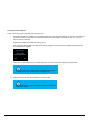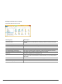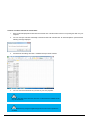
1
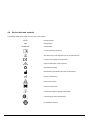
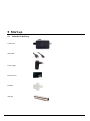
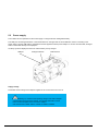
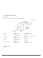
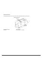
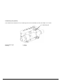
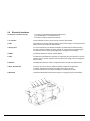
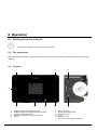
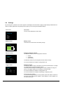
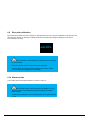
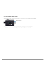
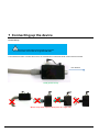
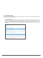
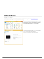
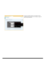
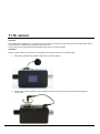
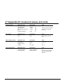
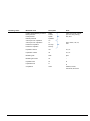
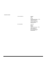
User Manual 302.904.000_01, 2015-09 Contents 1 Foreword ............................................................................3 2 Intended use .......................................................................4 3 Safety instructions ..............................................................5 4 Technical specifications ......................................................7 5 Start up .............................................................................16 6 Operation ..........................................................................24 7 Connecting up the device .................................................34 8 Reading out measurement data .......................................39 9 Configuration Tool ............................................................43 10 Profile Editor .....................................................................53 11 O2 sensor..........................................................................55 12 Measuring of respiratory data ...........................................56 13 Care and maintenance .....................................................61 14 Accessories and spare parts ............................................62 15 Disposal ............................................................................62 16 Appendix A: abbreviations and glossary ...........................63 17 Appendix B: measured values and units ..........................65 2 / 68 2015-09 1 Foreword Scope This documentation is valid for the product named: CITREX You will find the name CITREX on the bottom of the casing of the device. Software and firmware versions This operating manual is valid from the following versions: CITREX Software 3.8 CITREX Hardware 3 Older or newer versions may differ slightly from this manual. A word to our female users In this operating manual the male form “he” is used for simplicity and better understanding. However, this notwithstanding, it expressly includes all female users as well. 3 / 68 2015-09 2 Intended use The Product is intended to be used to test and verify the basic operation of medical devices or systems that produce a flow of gas or gas pressure, including ventilators and anesthesia systems. The intended user is a trained biomedical equipment technician who performs periodic preventative maintenance checks on patient monitors in service. Users can be associated with hospitals, clinics, original equipment manufacturers and independent service companies that repair and service medical equipment. The end user is an individual, trained in medical instrumentation technology. This Product is intended to be used in the laboratory environment, outside of the patient care area, and is not intended for use on patients, or to test devices while connected to patients. It is intended for over the counter use The CITREX is a compact, portable and easy-to-use measuring instrument. The CITREX is the right solution for measurements in the following areas: Flow Volume Pressure differences High pressure Ambient pressure Oxygen Temperature In addition, various respiratory parameters can be measured: Breathing rate Time Ratios Ti/Tcyc Tidal volume Volumes per minute Peak flow Pressure Compliance Triggers The CITREX is a measuring instrument for checking and calibrating breathing apparatuses. The CITREX may not be used for monitoring patients. During patient care with a ventilator, connection with the CITREX device is not permitted. 4 / 68 2015-09 3 Safety instructions 3.1 Symbol for danger, caution and notes This manual uses the symbols below to specifically point out residual dangers during correct application and usage as well as to emphasise important technical requirements. Instructions or commands/prohibitions to prevent damage of any kind, as well as tips and information on the use of the device. 3.2 Personnel Only persons who have the required technical training and the necessary experience may work on and with the CITREX. 5 / 68 2015-09 3.3 Responsibility and warranty The manufacturer assumes no responsibility or warranty, nor will he accept any liability if the user or third parties: do not use the device as intended. violate the technical specifications. modify the device in any way (through modifications, changes, etc.). use the device with accessories not indicated in the related product documentation. Although the device is characterised by a high quality and safety standard as well as being built and tested according to state-of-the-art technology, injuries and serious consequences cannot be entirely excluded in case of inappropriate use or misuse of the device. Thus the manual should be read carefully and kept within easy reach of the device. 3.4 Lifespan The maximum lifespan of the device is 10 (ten) years when handled according to the present user manual. To prevent damage or destruction of the device please always use CITREX on a flat surface as shown in the pictures of the user manual. 6 / 68 2015-09 4 Technical specifications 4.1 Measurement variables Flow and pressure measurements Measurement range Accuracy Flow measurements ± 300 sl/min *** ± 1.9 %* or ± 0.1 sl/min** Ambient pressure compensated yes Air und N2 Temperature compensated yes Channel pressure compensated yes -50 … +600 mbar Flow measurements ± 300 sl/min *** ± 1.9 %* or ± 0.1 sl/min** Ambient pressure compensated yes Temperature compensated yes Channel pressure compensated yes -50 … +600 mbar Flow measurements ± 140 sl/min *** ± 3 %* or ± 0.1 sl/min** Ambient pressure compensated yes 25°C … 30°C Temperature compensated yes Channel pressure compensated yes -50 … +600 mbar Flow measurements ± 300 sl/min *** ± 4 %* or ± 0.3 sl/min** Ambient pressure compensated yes 25°C … 30°C Temperature compensated yes Channel pressure compensated yes -50 … +600 mbar Flow measurements ± 80 sl/min *** ± 4 %* or ± 0.3 sl/min** Ambient pressure compensated yes 25°C … 30°C Temperature compensated yes Channel pressure compensated yes O2 / Air mixtures CO2 Heliox (21% O2 / 79% He) N2O / O2 mixtures 7 / 68 -50 … +600 mbar 2015-09 Pressure High 0 .. 10 bar ± 1 %* or ± 10 mbar** Difference ± 200 mbar ± 0.75 %* or ± 0.1 mbar** In the flow channel -50 .. 150 mbar ± 0.75 %* or ± 0.1 mbar** Barometer 500 .. 1150 mbar ± 1 %* or ± 5 mbar** Measurement variables Flow l/min, l/s, cfm, ml/min, ml/s Pressure bar, mbar, cmH2O, inH2O, Torr, inHg, hPa, kPa, mmHg, PSI Additional measuring variables Measurement range Accuracy Oxygen concentration (pressure comp. ≤150mbar) 0 .. 100 % ± 1 % O2** Gas temperature**** 0 .. 50 °C ± 1.75 %* oder ± 0.5 °C** Type of gas Air, Air/O2, N2O/O2, Heliox (21 % O2), N2, CO2 Gas standard ATP, ATPD, ATPS, AP21, STP, STPH, BTPS, BTPS-A, BTPD, BTPD-A, 0/1013, 20/981, 15/1013, 25/991, 20/1013, NTPD, NTPS Note: The greater tolerance is valid: * tolerance related to the measured value/** absolute tolerance *** In this user manual the unit sl/min is based on ambient conditions of 0°C and 1013 mbar (DIN 1343). **** CITREX measures the temperature of the gas inside its measurement chamber. As the CITREX warms up, it also warms the temperature of the measurement chamber, and thereby the temperature of the gas in the measurement chamber. The measurement chamber capacity is small, even for relatively high flows of gas (e.g., PIF@60 L/min). When compared with the temperature of the gas entering the CITREX flow channel inlet, the temperature of the gas inside the measurement chamber is higher, and the difference greater as the measurement channel warms up. Do not expect the temperature of the gas entering the CITREX flow channel inlet to be the same as the temperature of the gas displayed on the numeric screen of the CITREX, since the displayed temperature is what is measured inside the CITREX measurement chamber. 8 / 68 2015-09 Respiratory parameters Measurement range Accuracy Breathing Rate 1..1000 bpm. ±1 bpm or ± 2.5 %** AZ/min Time Ti,Te 0.05 .. 60 s ± 0.02 s Ration I:E 1:300 .. 300:1 ± 2.5 %* Ti/Tcyc 0 .. 100 % ± 5 %* Tidal volume Vti, Vte ± 10 l ± 2 %* or ± 0.20 ml (>6 sl/min)** Volume per minute Vi, Ve 0 .. 300 sl/min ± 2.5 %* Peakflow Insp. / Exp. ± 300 sl/min ± 1.9 %* or ± 0.1 sl/min** Pressure Ppeak, Pmean, PEEP, Pplateau 0 .. 150 mbar ± 0.75 %* or ± 0.1 mbar** Compliance Cstat 0 .. 1000 ml/mbar ± 3 %* or ± 1 ml/mbar** Trigger Adult, Pediatric, HFO Flow and volume (from default settings and adjustable levels) General informationen Display 26 x 33 mm Real time curves Flow, pressure, volume, temperature, oxygen, respiratory parameters Interfaces RS-232, USB, Ethernet, CAN, Analog Out, TTL AC input 100 .. 240 VAC, 50..60 Hz Battery operation 4 hours Dimensions (B x T x H) 11.4 x 6 x 7 cm Weight 0.4 kg Calibration interval annually Memory card yes Approvals CE CAN/CSA-C22.2 No. 61010-1-12 UL Std. No. 61010-1 (3rd Edition) EN 61326-1: 2006 / IEC 61326-2: 2005 (EMC) ETSI EN 300 328 V1.7.1 (2006-10) FCC part 15, subpart C, Digial Devices, emission Class B General requirements Note: The greater tolerance is valid: * tolerance related to the measured value/** absolute tolerance *** In this user manual the unit sl/min is based on ambient conditions of 0°C and 1013 mbar (DIN 1343). 9 / 68 2015-09 Operation principle of flow measurement A differential pressure measurement is used to determine the flow in the flow channel. In order to achieve the pressure difference, a linear flow element is used as a flow resistance. Linear flow element : dynamic viscosity of the gas [Pa s] : gas density [kg/m3] c1, c2: device-specific constants (channel geometry) Dynamic viscosity The viscosity of a medium is its resistance to flow and tear off of the flow. The viscosity depends strongly on the temperature. The viscosity of the medium is slightly dependent on pressure and humidity of the medium. Density Density is the unit of mass per unit volume of the medium. Density depends strongly on the pressure and temperature. The influence of environmental conditions is therefore the reason why the flow is occasionally transformed to standard conditions. Operating data Temperature: 15 to 40°C (59 to 104°F) Humidity: 10 to 90% RH Ambient pressure: 500 to 1150 mbar Storage and transportation conditions: –10 to 60°C (14 to 140°F) for 5 to 95% RH 10 / 68 2015-09 4.2 Standards for gas flow and volume values Gas Standard Volume measurement The CITREX calculates the measured flow and volume values based on the conditions in the standard specified. The following gas standards are supported by CITREX. Gas Standard Ambient Temperature and Pressure Ambient Temperature and Pressure Dry Ambient temperature and Pressure Saturated Ambient Pressure at 21°C ATP Standard Conditions USA STP Standard Conditions USA Humid Body Temperature and Pressure, Saturated Body Temperature and (Ambient) Pressure Saturated according to ISO 80601-212:2011 Body Temperature and Pressure Dry Body Temperature And (Ambient) Pressure Dry Standard Conditions DIN1343 Standard Conditions ISO 11975 (DIN 102) API Standard Conditions Cummings Standard 20°C / 1013 mbar STPH Normal Temperature and Pressure Normal Temperature and Pressure, Saturated NTPD ATPD ATPS AP21 BTPS BTPS-A BTPD BTPD-A 0/1013 20/981 15/1013 25/991 20/1013 NTPS Pressure Temperature Current ambient pressure Current ambient pressure Current ambient pressure Current ambient pressure 1013.25 mbar (760mmHg) 1013.25 mbar (760mmHg) Current ambient pressure + channel pressure Current ambient pressure Current Gas temperature Relative Humidity RH Current gas humidity Current Gas temperature 0% Current Gas temperature 100% 21.0°C (70°F) Current gas humidity 21.1°C (70°F) 0% 21.1°C (70°F) Current gas humidity 37.0°C (99°F) 100% 37.0°C (99°F) 100% Current ambient pressure + channel pressure Current ambient pressure 1013.25 mbar (760mmHg) 981 mbar (736 mmHg) 37.0°C (99°F) 0% 37.0°C (99°F) 0% 0.0°C (32°F) 0% 20.0°C (68°F) 0% 1013.25 mbar (14.7 psia) 991mbar (500ft Height) 1013.25 mbar (760mmHg) 1013.25 mbar (760mmHg) 1013.25 mbar (760mmHg) 15.0°C (60°F) 25.0°C (77°F) 20.0°C (68°F) 0% 0% 0% 20.0°C (68°F) 0% 20.0°C (68°F) 100% In this user manual the unit sl/min is based on ambient conditions of 0°C and 1013 mbar (DIN 1343). Please see Appendix B: parameters and units. There you will also find conversion factors for the units of measurement. 11 / 68 2015-09 Type of gas The appropriate gas type has to be set on the CITREX depending on which type of gas is to be measured. The following types of gas can be selected. Air (100%) Air/O2 Man. (Air-oxygen mixture in accordance with manual input. Default is 100% O 2.) Air/O2 Auto. (Air-oxygen mixture in accordance to sensor measurements of the internal oxygen cell.) N2O/O2 Man. (Nitrous oxide-oxygen mixture in accordance with manual input. Default is 100% O2.) Heliox (21% O2) N2 (100%) CO2 (100%) Standard conditions refer to defined conditions of pressure, temperature and in some cases humidity, which are the basis for the conversion of the effectively measured flow. It is therefore essential to check precisely which standard conditions the displayed values are based on! The currently set standard is shown in the numerical display. An incorrectly set gas or gas standard can lead to measurement errors of up to 20%. 12 / 68 2015-09 4.3 Power supply Input voltage of the power supply 100 .. 240 VAC, 50 .. 60 Hz Supply voltage 5 V DC Power consumption 2.5 .. 6 W 4.4 Battery operation Operating time on battery power 4 h* Recharging the battery Depending on which port is used, a full recharge takes 5 to 8 hours. The useful life of the battery is increased if the battery is only recharged when prompted by the device. The device emits visual and acoustic signals when the battery needs recharging. Please do not store the battery in a discharged state. Attention: total discharge can destroy the battery! Whenever the CITREX is recalibrated at our factory, the battery is tested. If battery capacity is below 70%, the battery will be replaced. 4.5 Regulations and approval CE CAN/CSA-C22.2 No. 61010-1-12 UL Std. No. 61010-1 (3rd Edition) EN 61326-1: 2006 / IEC 61326-2: 2005 (EMC) ETSI EN 300 328 V1.7.1 (2006-10) FCC part 15, subpart C, Digial Devices, emission Class B General requirements The device is not intended for use outside a building. Note: * Operation time will be reached in standalone operation (this means without any interfaces under use) 13 / 68 2015-09 4.6 Device label and symbols The following labels and symbols can be found on the CITREX. RS232 RS232 Interface USB USB interface SN BBXXXX Serial number Consult operating instructions The device may not be disposed of in the household waste.. Conforms to European Union directives Important information; refer to manual Recyclable packaging Manufacturer’s specification and date of manufacture Date of manufacturing Environment caution Lead free components Temperature range for storage and transport CSA monogram with C/US subscript No hazardous material 14 / 68 2015-09 4.7 Minimal PC requirements Microsoft® Silverlight 5 or higher Windows x86 oder x64 (64-bit mode support for IE only) 1.6 GHz or higher with 512-MB RAM Macintosh (Intel based) Intel Core Duo 1.83 GHz or higher with 512 RAM Microsoft® Windows® 8, Windows Server 2012, 7, 7 SP1, Windows Server 2008 SP2, Windows Server 2008 R2 SP1, Vista, Windows Server 2003, XP SP2 and SP3 Macintosh OS 10.5.7+ (Intel based) Ethernet network connection Screen resolution 1024 x 768 (1280 x 1024 recommended) 15 / 68 2015-09 5 Start up 5.1 Included in delivery CITREX H4 USB Cable Power supply Micro SD card Dustfilter Inlet pipe 16 / 68 2015-09 5.2 Power supply The CITREX can be operated from the mains supply or using the built-in rechargeable battery. The USB port, the analogue interface or the CAN interface on the upper side of the CITREX are used for connecting to the power supply. Use the USB cable in combination with the supplied universal power adaptor or connect the USB cable, analogue cable or CAN cable directly to the laptop/PC. A battery symbol is displayed at the front until the battery is fully charged. USB port Analogue interface CAN interface Supply voltage Permissible mains voltage of the adaptor supplied is 100 to 240 VAC at 50 to 60 Hz. Before switching on, check that the operating voltage of the mains adaptor corresponds to the local mains voltage. The required information can be found on the nameplate on the back of the adaptor. Only operate the CITREX with the original AC adaptor supplied. 17 / 68 2015-09 5.3 Mechanical connections. Flow channel The flow port can be used bi-directionally for the following measurements: Flow chanel Flow channel Flow (Air) Measurement range: Accuracy: -300..+300 sl/min +/-1.9% rdg. or +/-0.1 sl /min Volume Measurement range: Accuracy: 0..10 sl +/-2% rdg. or +/- +/- 0.2 sml (> 6 sL/min) *) Temperature Measurement range: Accuracy: 0..50°C +/-1.75% rdg. or 0.5°C Oxygen Measurement range: Accuracy: 0..100% +/-1% O2 Pressure in channel Measurement range: Accuracy: -50..150 mbar +/-0.75 rdg. or +/-0.1 mbar *) Average flow throughout inspiration 18 / 68 2015-09 Differential Pressure The differential pressure connections can be used for differential pressure measurements. Differential Pressure Measurement range: Accuracy: -200..200 mbar +/- 0.75% rdg. or +/-0.1mbar 19 / 68 2015-09 High pressure The high pressure port can be used for measuring pressures above 200 mbar. High pressure Measurement range: Accuracy: 0..10 bar +/-1% rgd. or 10 mbar For measurements up to 200 mbar, it is recommended to use the differential pressure port because its accuracy is up to 100 times higher. Pressures above 15 bar will destroy the high-pressure sensor! Do not use a tool to tighten the high pressure port (do this only manually), since this can damage the plastic casing. 20 / 68 2015-09 O2 Measuring cell (optional) The CITREX has an interface for an O2 measuring cell. For more information on this, see Chapter 11 O2 sensor O2 – Measuring cell Measurement range: Accuracy: 0..100 % +/-1% O2 21 / 68 2015-09 5.4 Electrical interfaces Connection to external circuits: - To connect to IEC XXXXX approved equipment only (e.g. IEC/EN 60950-1 or IEC/EN 61010-1). - To connect to telecom network not allowed. 1 O2 interface The O2 interface is used to connect the O2 sensor to the CITREX. 2 USB The USB port is used for operating with the mains power supply, to charge the device battery and can be used as an data interface. 3 Analog OUT For more information’s see Chapter 8 Reading out measurement dataThe Analog Out port is used for reading out analog signals, for connecting to an external trigger, for operation with the mains power supply and to charge the device battery. 4 RS232 The RS232 interface is used as a data interface. 5 CAN The device’s CAN interface is ready but not supported yet by the firmware. The CAN interface can be used for operation with the mains power supply and for charging the device battery. 6 Ethernet The Ethernet interface is used to configure the device as well as a data interface. 7 Micro SD Card Slot The micro SD card is used for software updates and device configurations. In addition measurement data can be output via the micro SD card. For more information’s see Chapter 8 Reading out measurement data 8 Bluetooth The device’s Bluetooth interface is ready but is not supported yet by the firmware. 1 2 3 4 5 6 8 7 22 / 68 2015-09 Interface definition: 3. Analog OUT Pin 1: Analog OUT 1 Pin 2: Analog OUT 2 Pin 3: Trigger Input Pin 4: VIN Pin 5: GND 4. RS232 Pin 1: NC Pin 2: RxD (Input) Pin 3: TxD (Output) Pin 4: GND 5. CAN Pin 1: VIN 12VDC ± 20% … 24VDC ± 20% Pin 2: CANH Pin 3: CANL Pin 4: Connectible electrical end resistance Pin 5: Pin 6: GND 120Ohm Pin1 23 / 68 Pin1 2015-09 Pin1 0… 5VDC ±1.8%, last ≥5kOhm 0… 5VDC ±1.8%, last ≥5kOhm ≥ 5 … ≤ 24VDC 12VDC ± 20% … 24VDC ± 20% 6 Operation 6.1 Switching the device on and off The device is switched on and off using the power button. 6.2 The start screen When the CITREX is switched on, the start screen appears. After about 3 seconds the numerical measurement values will be displayed. 6.3 Controls 1. 9. 3. 10. 4. 5. 8. 2. 1. 2. 3. 4. 5. 7. 6. Displays/changes measurement curves Displays/changes numerical measurement values Changes settings/saves data Shows menu/changes menu/zero calibration On/off 24 / 68 6. 7. 8. 9. 10. 2015-09 Battery on charge LED indicates flow direction LED function error Screen Bluetooth on/off Touch lock on/off (hold for 2 seconds) 6.4 Settings By pressing the X-symbol the info screen appears. This displays the device data. Tapping X again displays additional menu items for making adjustments. By pressing the O-symbol you can change the individual settings. Info screen Info screen The info screen displays the device data. Citrex H4 Owner: Company: Next Calib.: Software: Hardware: Battery screen Battery screen This shows the current state of the battery charge. Battery 80% Ethernet screen Setting the Ethernet interface The Ethernet interface can be configured as followed: Ethernet Default IP: Subnet: 192.168.1.1 255.255.255.0 Default Configured DHCP-Client The Ethernet interface is preconfigured with the “Default” setting. For more information see chapter 9 Configuration Tool Trigger screen Setting the trigger The start and stop of volume calculations as well as the determination of respiratory parameters is controlled by trigger events. The factory default settings contain triggers for adults, pediatrics and high frequency. The trigger setting can be changed to customers need. Trigger Adult Start: Flow: End: Flow: rising >3.0 l/min falling >3.0 l/min 60ms 60ms For more information see chapter 9 Configuration Tool For more information see chapter 12 Measuring of respiratory data. Set back Trigger to default To set back the trigger settings to factory default, press and hold the O-Button a few second. The screen shows question: “Set to default?”; to set to default, confirm with the O-Button. 25 / 68 2015-09 Gas Standard screen Standard ATP Setting the gas standard The CITREX calculates the devices measured flow and volume values according to the standard selected. For more information, see Chapter 4.2 Standards for gas flow and volume values. Ambient temp. and pressure Current gas temperature Current ambient pressure Current gas humidity Gas types screen Gas Type Air Humidity screen Humidity 50.0% X-Axis screen Setting gas types Depending on the gas to be measured, the appropriate gas type must be selected for the CITREX. For more information on the type of gas, see Chapter 4.2 Standards for gas flow and volume values. Setting humidity To get the best measurement accuracy, the humidity of the measured gas can be selected by tapping the O-Button in 10% steps. Set the percentage closest to the humidity of the measured gas. Setting the x-axis Here you can set the time window for the x-axis of the curve representation. X-Axis 0 … 2 Sec. 26 / 68 2015-09 O2 – Calibration screen O2 Calibration Oxygen Calibration only with air If the O2 option is enabled on the device, this menu allows the O 2 cell to be calibrated. The device will guide through the steps of calibration. Air 1. 2. Press to choose mode Press to start 3. 4. For starting an oxygen calibration with air press the X-symbol until the first screen appears. Press the O-symbol to continue. Apply 30l/min of air to the flow channel. Inside the parenthesis the actual flow is displayed. Press again the O-symbol to continue. The air calibration has started and will take duration of 114 seconds. Do not interrupt the gas flow through the flow-channel under any circumstances. At the end of the calibration a message will appear if the calibration was successful. The calibration can be stopped at any time by pressing the X- symbol. O2 Calibration O2 Calibration Apply 30 l/min (0) Flow 30 l/min O2 21 % Time rem: 114s Air 1. Press to start O2 Calibration Air calibrating.. Air successful Press any key to exit 2. 3. The Calibration only with air is a shorter and easier process. The measurement accuracy is not as good as the calibration with oxygen and air. 27 / 68 2015-09 Oxygen Calibration with oxygen and air If the O2 option is enabled on the device, this menu allows the O 2 cell to be calibrated. The device will guide through the steps of calibration. 1. 2. 3. 4. 5. 6. For starting an oxygen calibration with oxygen press the X-symbol until the first screen appears. Press the O-symbol to continue. Apply 30l/min of oxygen to the flow channel. Inside the parenthesis the actual flow is displayed. Press again the O-symbol to continue. The oxygen (100%) calibration has started and will take duration of 114 seconds. Do not interrupt the gas flow through the flow-channel under any circumstances. Apply 30l/min of air to the flow channel. Inside the parenthesis the actual flow is displayed. Press again the O-symbol to continue. The air calibration has started and will take duration of 114 seconds. Do not interrupt the gas flow through the flow-channel under any circumstances. At the end of the calibration a message will appear if the calibration was successful. The calibration can be stopped at any time by pressing the X- symbol. O2 Calibration O2 Calibration O2 Calibration Apply 30 l/min (0) Flow 30 l/min O2 21 % Time rem: 114s Apply 30 l/min (0) 100% O2 100% O2 calibr.. Air Press to start 1. 2. O2 Calibration Press to start O2 Calibration Air calibrating.. O2 and Air successful Flow 30 l/min O2 21 % Time rem: 114s 4. 3. 5. Press any key to exit The Calibration with Oxygen and air increases the accuracy of the oxygen measurement. Profiles screen Profiles Draeger Evita XL Evita standard profile Press to choose Press to load profile This screen loads profiles stored on the SD memory card in directory \Profiles. The profile name (= file name) is displayed in green text. The “Profile description” is displayed as white text. browses through all profiles loads the selected profile Details see chapter 10 Profile Editor 28 / 68 2015-09 6.5 Numerical values By pressing the □-symbol different screens with numerical values can be displayed. You can change between one, two, four or six measured values per screen. Specification for the Numerical Display: (1) Standard. The values displayed will be calculated using the selected standards. Choose from several common gas standards. (2) Trigger Indication. This icon indicates the detection of a trigger at the actual ventilation cycle. The icon is displayed for ½ second and indicates the start of a new inspiration. If this icon does not appear the trigger settings need to be adjusted. (3) Gas type currently selected. Depending on what type of gas is being measured, the device must be set accordingly. (4) Reading. Shows the actual measured value. (5) Measured variable. Shows the variable. Variables can be changed in the configuration monitor. (6) Unit of measurement. Shows the unit of the variable. Units can be changed in the configuration monitor. The individual values and units can be configured via the configuration tool. See Chapter 9 Configuration Tool. 1 4 6.6 2 3 ATP TA Air ATP Air 0.0 ATP Air Flow0.0 ATP Air l/minFlow 0.0 l/min Flow 0.0 l/min Flow l/min 5 6 Graphics values By pressing the Δ-symbol different screens with measured curves can be displayed. You can change between one or two measured curves per screen. The individual values and units can be configured via the online application. See Chapter 9 Configuration Tool. Flow Flow 29 / 68 l/min l/min Flow l/min Flow l/min 2015-09 6.7 Filter The display of the CITREX is updated every 500ms or in other words twice a second. The acquisition of new measuring values takes place every 5-8ms. Without using a filter the latest measured value will be displayed when updating the screen. Since each measurement is showing some noise it makes sense to average the values over a certain period of time. This is the meaning of the filter function. You can select one of the following filters: None (Display of the latest measured value without thresholds) Low (Mean value over 240ms) Medium (Mean value over 480ms) High (Mean value over 960ms) The standard filter is High. The filter setting can be changed in the CITREX configuration tool. For more information please see chapter 9 Configuration Tool. 6.8 Saving data By pressing and holding down the O-symbol for approximately 5 seconds, the current measured data will be stored on the micro SD card. During the data saving operation the following message is displayed on the screen: Data saved to DATAxx.CSV For further information on outputting measurement data, see Chapter 8 Reading out measurement data. Data saved to DATAxx.CSV 30 / 68 2015-09 6.9 Zero point calibration By pressing and holding down the X-symbol for approximately 5 seconds, zero-point calibration of the pressure and flow sensors is carried out. During the calibration operation the following message is displayed on the screen: Zero-Calibration Running. Zero Offset Calibrating, Please wait.. During a zero calibration it is important that no pressure or flow is applied to any connector! Remove protective caps before performing Zero Calibration. Attention: When performing the offset calibration using the X-symbol these warnings are not displayed on the display. 6.10 Warm-up time The CITREX sensors take approximately 10 minutes to warm up. For a short time after turning on the instrument some displays may vary slightly from Zero until the optimal operating temperature is reached (10 to 15 Min). Therefore zero calibrations must not be performed, as long the instrument is cold. 31 / 68 2015-09 6.11 Touch lock / touch unlock By pressing and holding down the Bluetooth button for 2 seconds, the touch lock gets enabled / disabled. Bluetooth button Touch locked Hold any key for 2s to unlock When the touch lock is activated and a symbol is pressed, a message on the screen appears: To disable the touch lock, hold down any symbol or the Bluetooth button for 2 seconds. 32 / 68 2015-09 6.12 Screen saver By default the screen brightness is reduced after 1 minute without touch activity to reduce display burn-in and extend the operating time on battery power. The screen saver setting can be changed in the CITREX configuration tool. For more information please see chapter 9 Configuration Tool. 33 / 68 2015-09 7 Connecting up the device General Set Up Best measurement results will be achieved without using filter. The measured Gas must be free of oil, grease and dust. The measurement setup can affect the accuracy of measurements. Tight bends, kinks or dents must be avoided. Flow direction Good general set up Worse set up: Kink, T-piece, elbow-piece etc. at gas inlet 34 / 68 2015-09 Measurement set up for ventilators Best measurement results will be achieved without using filter. The measured Gas must be free of oil, grease and dust. For check and calibration of ventilators, the usage of the inlet pipe in the following set up is recommended Breathing circuit Inlet Pipe CITREX Positive flow direction 35 / 68 2015-09 Testlung Set up for precise flow measurement The measured Gas must be free of oil, grease and dust. Best measurement results will be achieved by trigger setting “adult”. For precise flow measurement, the usage of the inlet pipe in the following set up is recommended. In any case the flow is very turbulent it is recommended to use between the inlet pipe and the CITREX the delivered “RT19” filter. Positive flow direction Flow direction positiv Negative flow direction Flow direction negativ 36 / 68 2015-09 Set up for dusty or contaminated gases Are the measured gases dusty or contaminated, the usage of the delivered “RT19” filter upstream of the inlet pipe is recommended. The measured gases must be free of oil or grease. Measurement setup: Flow direction 37 / 68 2015-09 Measurement set up for gases with high pressure CITREX compensates automatically the gas pressure in the flow channel up to 150mbar. For gas measurement with higher pressure, the high pressure port can be used. Therefore connect the gas outlet with the high pressure port. In the flow channel, pressures will be compensated up to 150mbar In combination with the high pressure port, the pressure can be compensated up to 600mbar Pressures in the flow channel, higher than 800mbar can damage the device Flow direction Flow direction 38 / 68 2015-09 8 Reading out measurement data Measured data could be read out by micro-SD-Card, the USB interface, the analog out interface the Ethernet interface or the RS-232 interface For information of usage the analog out interface, ask your distributor or directly imtmedical. For information of usage the RS-232 interface, ask your distributor or directly imtmedical. Storing measurement data on the micro SD card By pressing and holding down the O-symbol for approximately 5 seconds, the current measurement data will be stored on the micro SD card. During the storage operation the following message is displayed on the screen: Data saved to DATAXX.csv. A file with the name Dataxx.csv will be created on the micro SD card. 39 / 68 2015-09 Connection to the computer There are two ways to get to the data on the micro SD card: 1. Connect the CITREX to a computer via an USB port. When first connecting the CITREX to a computer it’s necessary to install a device driver. Please ask your system administrator for further support. The driver file “usb_cdc_ser.inf” is stored on the micro SD card. Usage of the CITREX as an USB mass storage device: When connecting the CITREX to a computer the device is asking if it should be used as a USB mass storage device. The following screen appears: USB Mode Use as USB mass storage device? YES NO If there was no choice taken during 5 seconds the device won’t be recognized as USB mass storage device. During the usage of the CITREX as an USB mass storage device no configuration can be made with the configuration tool. 2. Pressing the micro SD card once releases it from the CITREX. We recommend only using the supplied original micro SD card to operate the CITREX. 40 / 68 2015-09 Reading out the data on the computer The following files exist on the card: Directory \ File Description CFG, SCR, TRG The CFG, SCR and TRG files are needed by CITREX to activate internal processes. Clientaccesspolicy.xml This file is needed for the configuration tool ClientBin\ConfigurationWeb.xap This folder is needed for the configuration tool DATA The saved measurement values are stored in this folder. Formatter\AboutReportFormatter.txt This TXT file describes the procedure for formatting saved data in an Excel file. Formatter\ReportFormatter.xlsb This is the actual Excel file template in in which the saved data is formatted. Formatter\SetupReportFormatter.bat This batch file is needed to format the data in an Excel file. index.html This file is needed for the configuration tool logs The CITREX continuously records information about its functions and saves them as Log Files. This information is used exclusively for correcting problems and errors. ProfileEditor.html Browser-based editor to create and edit settings profiles Profiles \ *.profile Profile settings file, can be loaded via Profiles in the menu USB-Driver\ubs_cdc_ser.inf Driver for the USB device identification User Manual Contains user manuals in PDF format 41 / 68 2015-09 Creation of an Excel file with the saved values 1. Open the file SetupReportFormatter.bat with a double click. This file creates a macro for importing the data onto your computer. 2. You can now open CSV files individually in the DATA folder with a double click. An Excel template is opened and the following message displayed: 3. Confirmed the formatting with YES. A CITREX test report will be created. 4. You can now use the Excel file as you want for your own purposes. Attention: The files on the micro SD card may not be renamed or deleted under any circumstances. We recommend only using the supplied original micro SD card to operate the CITREX. 42 / 68 2015-09 9 Configuration Tool 9.1 Device configuration It is possible to configure the CITREX by the Ethernet interface. Real time measurement data as well as real time curves can be displayed and even analysed on the computer monitor. The communication between the CITREX and the computer is bidirectional. These means wherever settings were changed those will be take over on both sides. To ensure that the configuration properly runs on the computer it is necessary to have Silverlight 5 installed on one of the following internet browsers: 1. Internet Explorer 7+ Safari 4+ Firefox 3.6+ Connect the CITREX to a network or directly to a computer by using the Ethernet interface. There are three different ways how to configure the Ethernet interface. Press the X-symbol on the device until the Ethernet screen appears. Use the O-symbol to change between Default, Configured and DHCP-Client: 43 / 68 2015-09 Default (recommended for direct connection): Connect the CITREX directly to a computer by using a merchantable Ethernet cable. In this configuration the IP address of the CITREX is preconfigured to: IP Address: 192.168.1.1 Subnet Mask: 255.255.255.0 Configure the Computer network to the following settings: IP Address: 192.168.1.2 (or any IP Address between 192.168.1.2 - 192.168.1.255) Subnet Mask: 255.255.255.0 To take over this configuration open the network connection on the computer. Control Panel Network and Internet Change adapter settings 44 / 68 2015-09 Choose the network card the CITREX is connected to and open its the properties. Open the properties of the Internet Protocol 4 (TCP/IPx4). The IP Address can now be changed. Save the settings and close the windows. Configured (recommended for network without DHCP-Server): To set a customized IP Address it is necessary to open first a Default or DHCP-Client connection. With the configuration tool under “Configuration interface” a customized “IP Address” and “Subnet Mask” can be allocated. Connect the CITREX to the network. DHCP Client (recommended for network with DHCP-Server): Connect the CITREX to a network by using a merchantable Ethernet cable. After a few seconds the CITREX has reconfiguring an IP Address and the Subnet Mask. 45 / 68 2015-09 2. 3. Make sure the following files are stored on the micro SD card: ClientBin folder including ConfigurationWeb.xap clientaccesspolicy.xml index.html In any case the micro SD card got lost or the files were deleted; please contact the distributor or directly imtmedical support. Keep in mind that the micro SD card has to be inserted the CITREX during the usage of the configuration tool. Otherwise the settings won’t be saved. 4. For the first connection choose between Default and DHCP-Client and open an internet browser. To start the configuration tool enter the IP Address which is displayed on the CITERX screen in the address bar of your browser. The Configuration Tool is downloaded to the computer and establishes a connection. WARNING: There is a limitation of one connection per device. This means as long as the configuration tool is open, the CITREX device cannot be configured from another computer. 46 / 68 2015-09 5. After a few seconds the CITREX is successfully connected to the computer. The screen below appears. 6. Device summary Change the owner name or the company name to personalize the CITREX. 47 / 68 2015-09 7. Configuration values Change the displayed numeric values or the corresponding units on the CITREX by using the pull down menus. 8. Configuration curves Change the displayed curves or the corresponding units on the CITREX by using the pull down menus. 48 / 68 2015-09 9. Configuration Triggers Set one of the three preconfigured trigger on the CITREX by using the button “Active”. The active trigger is differently coloured from the non-active. The trigger parameters can be changed by using the pull-down menus. It’s possible to take over the preconfigured trigger settings by pressing the button “Reset to defaults”. Learn more about trigger configuration in Chapter 12 Measuring of respiratory data 10. Configuration Interface Change the Ethernet IP configuration or change the analog outputs measurement values by using the pull down menus 49 / 68 2015-09 11. Configuration miscellaneous Change different specific measurement parameters by using the pull down menus. 50 / 68 2015-09 9.2 Monitoring option The monitoring option is optional and not included in the scope of delivery. To activate this option subsequently, please contact the distributor or the imtmedical support. 12. Monitoring numerics View real-time measurement values direct on the computer monitor. Actual measurement value as well as minimum, maximum and average is calculated for each value. By pressing the button “Reset statistics” the statistic calculation can be reset. To export the actual displayed measurement values press the button “Export”. An explorer window will open in which the file type as well as the file location has to be defined. The following storage types are possible: Excel XML (*xml) and CSV (*csv). 51 / 68 2015-09 13. Monitoring panels View real-time curves direct on the computer monitor. Change the chart value by using the pull down menus. Record measurement values over a time range of 300 seconds by pressing “Run”. Press “Freeze and the record will stop. Once in freeze mode, the sliders of the time bar are activated. Choose with the sliders the time period to visualize data in the detailed charts. Press the button “Export” to export the actual displayed chart. An explorer window will open in which the file type as well as the file location has to be defined. The following storage types are possible: Png (*.png). . 52 / 68 2015-09 10 Profile Editor 10.1 Create a Profile Create or edit a profile using the Profile Editor available on CITREX’ SD memory card or on www.imtmedical.com. Use a profile on CITREX via it’s menu (see chapter 6.4 Settings). Access the Profile Editor and all stored profiles on CITREX’ SD memory card. Microsoft Internet Explorer or the Silverlight browser plugin is required to run Profile Editor. Load and save configured profiles to SD card D:\Profiles directory. The file name is the profile name. Note: limit to 15 characters to fit CITREX’ display. 53 / 68 2015-09 Configure all CITREX settings via the different screens available: Setup of numeric and curve displays, trigger settings, units, gas standards 54 / 68 2015-09 11 O2 sensor Activation The CITREX has an interface for an oxygen sensor. If the device has not been configured in the factory for the oxygen option, this must be done subsequently by entering an activation code. You can obtain the oxygen option and the activation code from your CITREX supplier. Installation With the oxygen option you will receive a kit consisting of an oxygen sensor and a connection cable. 1. Remove the protective cap (rubber stopper) from the sensor opening. 2. Secure the O2 sensor by turning it in the clockwise direction and connect the sensor with the device using the sensor cable. 55 / 68 2015-09 12 Measuring of respiratory data General To be able to measure key respiratory data it is mandatory that the CITREX can read out a breathing cycle from the measured pressure and/or flow chart curves. This is controlled via the triggers. Therefore it is of great importance to correctly define the start and stop triggers, as this can significantly influence the measurement results. The set triggers are used to trigger the breathing cycles. Thus it is very important that the triggers are set correctly before starting respiratory data measurement. The start trigger is interpreted as the start of the inspiration phase. The stop trigger is interpreted as the end of the inspiration phase and the start of the expiration phase. The expiration continues until the next start trigger is activated. 56 / 68 2015-09 Connection to the respiratory apparatus Basically there are three different methods of connecting the CITREX to the respiratory apparatus: Downstream of the Y-piece CITREX Test Lung Ventilator In the inspiration duct upstream of the Y-piece CITREX Test Lung Ventilator In the expiration duct upstream of the Y-piece CITREX Ventilator Standard trigger values Test Lung As the CITREX can measure flow in both directions, it makes sense to use connection method A. In this measurement setup, flow is usually chosen as the trigger value. For this reason the flow triggers are stored as standard values in the device and can be reset anytime. The standard trigger values for the flow trigger for adult breathing, for example, are: Starttrigger: Flow > 3 l/min Endtrigger: Flow < -3 l/min With the connection methods B and C, pressure is usually chosen as the trigger signal. In this case the standard values are as follows: Starttrigger: Pressure > 1 mbar Endtrigger: Pressure < 1 mbar Baseflow The base flow designates a constant flow which should not be considered for the calculation of the volume. If there is a defined leakage in the system, for example, where 3 l/min air is discharged constantly, the 3 l/min do not count as inspiration volume. By entering Base flow: on 3.0 l/min the volume calculation in our example could be corrected. Finding the correct trigger settings When you set a trigger for the first time, it is important to know the curve of the signal used for the trigger (flow or pressure). Here are some examples that also indicate possible problems. 57 / 68 2015-09 Flow curve downstream the Y-piece This is an example of a flow curve downstream of the Y-piece. The standard triggers (> 3 l/min/< –3 l/min) can be used without any problem. In such situations it is important to keep in mind that the trigger is significantly higher than the noise of the base line, as otherwise faulty triggering can be released. Flow curve upstream of the Y-piece Faulty triggering! This curve shows the flow curve in the inspiration duct upstream of the Y-piece. The first two circles mark the triggers that should be used here. The top figure shows that a small faulty signal is still visible at this measuring point after the inspiration which has been caused by switching the valves. This results in faulty triggering! 58 / 68 2015-09 Attention: Flow may not be used here as a trigger! The pressure curve must be used. Pressure curve upstream of the Y-piece In this case the standard triggers can be used for the pressure curve: (> 1 mbar / < 1 mbar). Of course it must also be pointed out that the trigger is significantly higher than the noise of the base line. Otherwise the trigger value must be increased. Special cases In measurement technology there can basically always be a deviation from the standard variants to achieve an even more exact result. However, it must be observed that very exact results are achieved with the settings described so far, exceeding the accuracy of all respiratory equipment. Measurement errors inherent in the overall system occur both in the respiratory apparatus and in the CITREX H4. However, the values displayed may vary as it may be that not exactly the same thing has been measured and compared. 59 / 68 2015-09 Inspiration volume Vti If the breathing curve shows a plateau or a break, a tiny flow can still be measured during this time. A lot of breathing equipment does not include these tiny flows in their Vti calculations. Using the following trigger settings, this can also be prevented in the CITREX: In this diagram, S corresponds to the start trigger and E to the end trigger. Expiration volume Vte This is the analogue setting for Vte: Here, too, the start trigger must be set to S and the end trigger to E. 60 / 68 2015-09 13 Care and maintenance Guidelines for care and mainteneance Careful maintenance according to the guidelines is a precondition for assuring safe and reliable operation of the CITREX. Only components recommended by the manufacturer may be used. The manufacturer’s guidelines and maintenance instructions must be adhered to. Notes on the replacement of components The maintenance tasks described below may only be carried out by persons familiar with the CITREX. All other repairs beyond that may only be carried out by authorised trained personnel. Please also observe the relevant manufacturer’s instructions. Preventive cleaning and maintenance To maintain the accuracy and reliability of your appliance in the long term, the following maintenance tasks must be carried out on a regular basis: During operation Use the filter supplied Every four weeks Check the filter for contamination. To do this, connect the filter inlet and outlet with the differential pressure connection using two T-pieces. In this way, the pressure loss across the filter can be measured. The pressure loss for a flow of 60 l/min may not exceed 2 mbar. If it does, the filter must be replaced. Every 12 months Factory calibration to ensure reliable measurement. 61 / 68 2015-09 14 Accessories and spare parts Ordering adress imtmedical ag Gewerbestrasse 8 CH-9470 Buchs Switzerland Tel: +41 (0)81 750 66 99 E-Mail: [email protected] Options Item Item number Oxygen option Monitoring option SmartLungTM Adult SmartLungTM Infant EasyLung TM 301.863.000 302.239.000 300.162.000 300.400.004 300.756.000 For further accessories and spare parts see www.imtmedical.com 15 Disposal The operating company is responsible for disposal of the device. The device must be delivered (free and with duty paid) to the manufacturer for disposal. The device can be handed over to a licensed private or public collecting company. The device can be dismantled into individual components, and recycling or disposing of these then be carried out in the correct manner. If disposal is carried out by the operating company itself, the regulations for disposal depend on the country concerned and are subject to its laws and legal requirements. The rules and regulations concerned can be obtained from the responsible authority. In this regard, waste is to be recycled or disposed of: without danger to human health. without using procedures or methods harmful to the environment, particularly to the water, air, soil, flora and fauna. without creating noise or smell. 62 / 68 2015-09 16 Appendix A: abbreviations and glossary A A AC AT B bar Base flow C °C Amp Alternating current Amp time-lag 1 bar = 14.50 psi The base flow is a constant flow which should not be considered for the calculation of the volume. Cstat Degrees Celsius Conversion of Celsius (C) to Fahrenheit (F): F = 9*C/5 + 32 Statistical compliance D DAC dBA DC DIN Direct access control Decibel measured with A-filter Direct current Deutsche Industrienorm (German Industry Standard) E EMC Electro-magnetic compliance F °F FCC RJ-10 Degrees Fahrenheit Conversion of Fahrenheit (F) to Celsius (C): C = (F–32)*5/9 Plug for external trigger (telephone plug according to FCC registration , U.S. Federal Communications Commission; RJ = Registered Jack) G GND Ground H h HF Hz Hour High frequency Hertz (1 Hz = 1 s –1 ) I I:E IP Breathing-time ratio: inspiration to expiration Protection class according to standard L l lb, lbs LED l/s Litre Pound Light emitting diode Litre per second 63 / 68 2015-09 M Max., max. mbar min Min., min. ml mm Maximal Millibar (1 mbar = 10-3 bar) Minute Minimal Millilitre (1 ml = 10-3 l) Millimetre (1 mm = 10-3 m) N nl/min Standard litre per minute (converted to ambient conditions of 0°C and 1013 mbar) P PEEP PF Exp. PF Insp. Pmean Ppeak Pplateau ppm prox. psi Positive End Expiratory Pressure Peak flow during expiration Peak flow during inspiration Mean pressure Peak pressure Plateau pressure at the end of inspiration Parts per million (1*10-6) Proximal Pressure per square inch (1 bar = 14.50 psi) R rdg. RH RJ-10 FCC RS-232 reading (from the measured value) Relative humidity Plug for external trigger (telephone plug according to FCC registration, U.S. Federal Communications Commission; RJ = Registered Jack) Serial interface T Ti/TCycle Ratio: inspiration time to time of one breathing cycle V V VA VAC VDC Volt Apparent power consumption of the device Volt alternating current Volt direct current μm Micrometre (1 μm = 10-6 m) 64 / 68 2015-09 17 Appendix B: measured values and units Pressure values Flow values Meteorological values Gas concentrations Measured value Description Units Ambient pressure High pressure High pressure flow channels Pressure difference P Atmo. P High P (HF) Measured value Description Units Flow Flow l/min, ml/min, cfm, l/s, ml/s Measured value Description Units Temperature Oxygen content Volume Temp. O2 Vol. (HF) °C, K, °F % ml, l, cf Measured value Description Units Gas concentration Partial pressure Gas concentration Partial pressure % mbar, bar, inH2O, cmH2O, psi, Torr, inHg, mmHg, hPa, kPa mbar, bar, inH2O, cmH2O, psi, Torr, inHg, mmHg, hPa, kPa P Diff. 65 / 68 2015-09 Breathing values Measured value Description Units Positive End Expiratory Pressure Mean pressure Peak pressure Plateau pressure Volume per min: expiration Volume per min: inspiration Peak flow: inspiration Peak flow: expiration PEEP Pmean Ppeak Pplateau Ve Vi PF Insp. PF Exp. mbar, bar, inH2O, cmH2O, psi, Torr, inHg, mmHg, hPa, kPa Expiration volume Vte ml, l, cf Inspiration volume Vti ml, l, cf Breathing rate Rate bpm Breathing-time ratio I:E - Expiration time Te s Inspiration time Ti s Compliance Cstat ml/mbar, l/mbar, ml/cmH2O, ml/cmH2O 66 / 68 2015-09 l/min, ml/min, cfm, l/s, ml/s Conversion factors 1 mbar equivalent to 0.001 bar 100 Pa 1 hPa 0.1 kPa 0.75006 Torr (760 Torr = 1 atm.) 0.75006 mmHg (at 0°C) 0.02953 inHg (at 0°C) 1.01974 cmH2O (at 4°C) 0.40147 inH2O (at 4°C) 0.01450 psi, psia 1 bar equivalent to 1000 mbar 0.1 Pa 1000 hPa 100 kPa 750.06 Torr (760 Torr = 1 atm.) 750.06 mmHg (at 0°C) 29.53 inHg (at 0°C) 1019.74 cmH2O (at 4°C) 401.47 inH2O (at 4°C) 14.50 psi, psia 67 / 68 2015-09 Imtmedical ag . Gewerbestrasse 8 . 9470 Buchs . Switzerland T +41 81 750 66 99 . www.imtmedical.com 68 / 68 2015-09