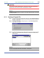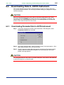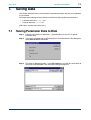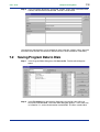
1
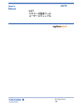
User’s
Manual
Model VJ77
PC-based Parameters
Setting Tool
IM 77J01J77-01E
IM 77J01J77-01E
Yokogawa Electric Corporation
5th Edition
<Toc> <Ind> <Rev>
<Introduction>
i
Introduction
This instruction manual describes the functions and operation of the Model VJ77 PC-based
Parameters Setting Tool.
■ Configuation of This Manual
This manual consists of 12 chapters.
● Chapter 1 VJ77 PC-based Parameters Setting Tool
Gives an overview of VJ77 and describes its functions and the operating environment.
● Chapter 2 Setup
Describes how to setup the hardware and software required to use VJ77.
● Chapter 3 Basic Operation
Describes the basic operation and main windows of VJ77.
● Chapter 4 Setting Parameters
Describes how to set parameters of JUXTA instruments.
● Chapter 5 Setting a Program
Describes how to set a program for JUXTA computing units.
● Chapter 6 Uploading and Downloading Data from/to JUXTA
Describes how to upload parameter or program data inside JUXTA instruments from VJ77
and how to download the data to JUXTA instruments.
● Chapter 7 Saving Data
Describes how to save parameter or program data on a disk.
● Chapter 8 Printing Data
Describes how to print parameter or program data.
● Chapter 9 Monitoring Input/Output Values
Describes how to monitor the I/O values of JUXTA instruments and how to view the result
of self-diagnosis.
● Chapter 10 Adjusting JUXTA Instruments
Describes how to adjust JUXTA instruments’ input/output, how to correct the wiring resistance, and others.
● Chapter 11 Troubleshooting
Describes how to solve problems when any trouble has occurred while using VJ77.
● Appendix
Describes how to set a password (security function).
Media No. IM 77J01J77-01E (FD)
5th Edition : Feb. 2011 (YK)
All Rights Reserved Copyright © 1999, Yokogawa Electric Corporation
IM 77J01J77-01E
5th Edition : Feb. 28, 2011-00
<Toc> <Ind> <Rev>
<Introduction>
ii
■ Intended Readers
This manual is intended for people familiar with the functions of JUXTA signal conditioners
and capable of working with Windows, such as instrumentation and control engineers and
personnel in charge of maintaining instruments and control equipment.
■ Related Documents
● Instruction manuals for individual JUXTA signal conditioners
These manuals provide information about the procedure of installation and wiring of signal
conditioners and parameter lists.
■ Trademark
All the brands or names of Yokogawa Electric’s products used in this manual are either
trademarks or registered trademarks of Yokogawa Electric Corporation.
Windows is a registered trademark of Microsoft Corporation, USA.
IM 77J01J77-01E
5th Edition : Feb. 28, 2011-00
<Toc> <Ind> <Rev>
<Introduction>
iii
Visual Inspection and Cross-check of
Accessories
On receiving the product, visually inspect it for any damage.
■ Checking Model and Suffix Codes
Make sure that the model and suffix codes of the delivered product are as specified in your
order.
Model
Suffix code
VJ77
Description
PC-based parameters setting tool
-E10
For use with IBM PC/AT compatible personal computers (English version)
■ Checking the Package Contents
Make sure that the delivered package contains all of the following items.
• VJ77 PC-based Parameters Setting Tool CD ...................................... 1 disk
• Communication adapter ...................................................................... 1 unit
• Communication cable with 9-pin D-sub female connectors at both ends ........ 1 cable
• JUXTA communication cable (3-pin connector type) ............................ 1 cable
• JUXTA communication cable (5-pin connector type) ............................ 1 cable
• Adapter for modular-jack ..................................................................... 1 unit
• User’s manual (this manual: IM 77J01J77-01E) .................................. 1 copy
IM 77J01J77-01E
5th Edition : Feb. 28, 2011-00
<Toc> <Ind> <Rev>
<Introduction>
iv
Documentation Conventions
■ Documentation Conventions
The following conventions are used throughout this manual:
Item
Usage
The names of named dialog boxes, windows,
and views are written in title cap and refer to
the exact titles.
Parameter Setting Menu dialog box
The names of unnamed windows, dialog
boxes, and views are written in all lowercase
letters.
document window
Commands (including buttons) in a dialog
box or window and menu commands are
written in boldface.
Click OK.
Click Options.
From the File menu, choose Exit.
Dialog box elements, such as text boxes, list
boxes, option buttons, and check boxes, are
also written in bold face and refer to their
exact labels.
Select the Spaces check box.
Click to clear the Bookmarks check box.
In the Font box, type or select the font
you want to use.
In the File Name box, enter a file name.
Characters to be typed by the user via
keyboard are written in monotype font.
Type JUXTA in the Model box.
Gantt view
print preview
WARNING
Indicates that operating the hardware or software in a particular manner may damage it or
result in a system failure.
CAUTION
Draws attention to information that is essential for understanding the operation and/or
features of the product.
TIP
Gives additional information to complement the present topic.
See Also
Gives reference locations for further information on the topic.
IM 77J01J77-01E
5th Edition : Feb. 28, 2011-00
<Toc> <Ind> <Rev>
<Introduction>
v
■ Illustrations in This Document
(1) Illustrations and figures presenting this product or its functions in this manual may not
be exactly the same as the actual product or functions so as to simplify understanding.
(2) Figures and illustrations representing the displays may differ from the actual displays
in regard to the position and/or display characters (uppercase or lowercase, for
example), but not to an extent that impairs a correct understanding of the functions
and the proper setting operation.
IM 77J01J77-01E
5th Edition : Feb. 28, 2011-00
<Toc> <Ind> <Rev>
<Introduction>
vi
Notice
■ Regarding This User’s Manual
(1) This manual should be passed on to the end user. Keep this manual in a safe place.
(2) Read this manual carefully to gain a thorough understanding of how to operate this
product before you start using it.
(3) This manual is intended to describe the functions of this product. Yokogawa Electric
Corporation (hereinafter simply referred to as Yokogawa) does not guarantee that
these functions are suited to the particular purpose of the user.
(4) Under absolutely no circumstances may the contents of this manual, in part or in
whole, be transcribed or copied without permission.
(5) The contents of this manual are subject to change without prior notice.
(6) Every effort has been made to ensure accuracy in the preparation of this manual.
Should any errors or omissions come to your attention however, please contact your
nearest Yokogawa representative or our sales office.
■ Regarding Protection, Safety, and Prohibition Against Unauthorized
Modification
(1) In order to protect the product and the system controlled by it against damage and
ensure its safe use, make sure that all of the instructions and precautions relating to
safety contained in this document are strictly adhered to. Yokogawa does not guarantee safety if the product is not handled according to these instructions.
(2) The following safety symbols are used in this manual.
● Symbols used on the product and in this manual
CAUTION
This symbol on the product indicates that the operator must refer to an explanation in the
user’s manual to avoid the risk of injury or death of personnel or damage to the instrument.
The manual describes how the operator should exercise special care to avoid electrical
shock or other dangers that may result in injury or the loss of life.
Protective ground terminal:
This symbol indicates that the terminal must be connected to ground prior to operating
the equipment.
Function ground terminal:
This symbol indicates that the terminal must be connected to ground prior to operating
the equipment.
IM 77J01J77-01E
5th Edition : Feb. 28, 2011-00
<Toc> <Ind> <Rev>
<Introduction>
vii
■ Exemption from Responsibility
(1) Yokogawa does not make any warranties regarding the product except those mentioned in the WARRANTY that is provided separately.
(2) Yokogawa assumes no liability to any party for any loss or damage, direct or indirect,
caused by the use or any unpredictable defect of the product.
(3) Be sure to use the spare parts approved by Yokogawa when replacing parts or
consumables.
(4) Modification of the product is strictly prohibited.
(5) This software may be used with one specified computer only. You must purchase
another copy of the software for use on each additional computer.
(6) Copying the software for purposes other than backup is strictly prohibited.
(7) Store the compact disk (original media) containing this software in a secure place.
(8) Reverse engineering such as the disassembly or decompilation of software is strictly
prohibited.
(9) No portion of the software supplied by Yokogawa may be transferred, exchanged,
leased, or sublet for use by any third party without the prior permission of Yokogawa.
IM 77J01J77-01E
5th Edition : Feb. 28, 2011-00
Blank Page
<Toc> <Ind> <Rev>
<Introduction>
ix
Model VJ77
PC-based Parameters Setting Tool
IM 77J01J77-01E 5th Edition
CONTENTS
Introduction........................................................................................................... i
Visual Inspection and Cross-check of Accessories ...........................................iii
Documentation Conventions ..............................................................................iv
Notice ...................................................................................................................vi
1.
VJ77 PC-based Parameters Setting Tool ............................................... 1-1
1.1
2.
1.1.1
What is VJ77? .................................................................................. 1-1
1.1.2
Functions .......................................................................................... 1-1
1.2
Conceptual View of VJ77 ................................................................................ 1-2
1.3
Operating Environment and Wiring Specifications ...................................... 1-3
1.3.1
System Requirements ...................................................................... 1-3
1.3.2
Communication Adapter ................................................................... 1-3
1.4
External View of Communication Adapter ..................................................... 1-4
1.5
Precautions When Communicating with JUXTA ........................................... 1-5
Setup ....................................................................................................... 2-1
2.1
Installing VJ77 ................................................................................................. 2-1
2.2
Uninstalling VJ77 ............................................................................................ 2-2
2.3
Connecting JUXTA Instrument to Personal Computer ................................. 2-3
2.4
3.
An Overview of VJ77 and Its Functions ........................................................ 1-1
2.3.1
Items Required for Connection ......................................................... 2-3
2.3.2
How to Connect ................................................................................ 2-3
Setting the Communication Port .................................................................... 2-4
Basic Operation ...................................................................................... 3-1
3.1
Starting VJ77 ................................................................................................... 3-1
3.2
Quitting VJ77 ................................................................................................... 3-2
3.3
Dialog Box Elements and Functions ............................................................. 3-3
3.4
Basic Operation .............................................................................................. 3-5
3.4.1
Operation Using a Mouse ................................................................. 3-5
3.4.2
Operation Using Keyboard ................................................................ 3-6
3.5
Display Sequence ........................................................................................... 3-8
3.6
Main Dialog Boxes and Their Functions ........................................................ 3-9
3.6.1
DISPLAY Dialog Box......................................................................... 3-9
3.6.2
SET Dialog Box ................................................................................ 3-9
3.6.3
ADJUST Dialog Box ....................................................................... 3-10
3.6.4
Program Editor Dialog Box.............................................................. 3-10
IM 77J01J77-01E
5th Edition : Feb. 28, 2011-00
<Toc> <Ind> <Rev>
4.
5.
6.
4.1
Displaying the Parameter Setting Dialog Box ............................................... 4-1
4.2
Setting Parameters ......................................................................................... 4-3
9.
Entering a Setting Value and Writing It to JUXTA ............................... 4-3
4.2.2
Notes on Setting Parameters ............................................................ 4-4
4.2.3
Selecting an Item from a List Box and Writing It to JUXTA ................. 4-5
5.1
Opening Program Editor Dialog Box ............................................................. 5-1
5.2
Setting a Program ........................................................................................... 5-3
5.2.1
Creating a New Program .................................................................. 5-3
5.2.2
Functions to Facilitate Program Coding ............................................ 5-6
5.2.3
Converting Free (User) Program Automatically ................................. 5-8
Uploading and Downloading Data from/to JUXTA ................................ 6-1
Uploading Data to Your PC ............................................................................. 6-1
6.1.1
Uploading Parameter Data from JUXTA Instrument .......................... 6-1
6.1.2
Opening a Parameter File ................................................................. 6-3
6.1.3
Uploading Program Data from JUXTA Instrument ............................. 6-4
6.1.4
Opening a Program File .................................................................... 6-5
Downloading Data to JUXTA Instrument ....................................................... 6-6
6.2.1
Downloading Parameter Data to JUXTA Instrument .......................... 6-6
6.2.2
Downloading a Program to JUXTA Instrument .................................. 6-7
Saving Data ............................................................................................. 7-1
7.1
Saving Parameter Data to Disk ...................................................................... 7-1
7.2
Saving Program Data to Disk ......................................................................... 7-2
Printing Data ........................................................................................... 8-1
8.1
Printing Data ................................................................................................... 8-1
8.2
Previewing the Print Image ............................................................................ 8-3
8.3
Saving Print Data As a Comma-separated Value File ................................... 8-4
Monitoring I/O Values ............................................................................. 9-1
9.1
10.
4.2.1
Setting a Program ................................................................................... 5-1
6.2
8.
x
Setting Parameters ................................................................................. 4-1
6.1
7.
<Introduction>
Opening the Monitor Dialog Box .................................................................... 9-1
Adjusting JUXTA Instruments .............................................................. 10-1
10.1
Opening the Adjusting Dialog Box .............................................................. 10-1
10.2
Performing Fine Adjustment of Input .......................................................... 10-2
10.2.1
Adjusting the Zero Point of Input ..................................................... 10-2
10.2.2
Adjusting the Input Span ................................................................. 10-2
10.3
Correcting the Output ................................................................................... 10-3
10.4
Setting Wire Resistance Compensation ...................................................... 10-4
10.5
Using the Forced Output Function .............................................................. 10-5
11.
Troubleshooting .................................................................................... 11-1
12.
Appendix ............................................................................................... 12-1
12.1
Setting the Password .................................................................................... 12-1
12.2
Changing the Password ............................................................................... 12-2
Revision Information ............................................................................................ i
IM 77J01J77-01E
5th Edition : Feb. 28, 2011-00
<Toc> <Ind>
1.
<Chapter 1 VJ77 PC-based Parameters Setting Tool>
1-1
VJ77 PC-based Parameters Setting Tool
This chapter gives an overview of the VJ77 tool and describes its operating environment.
1.1
An Overview of VJ77 and Its Functions
1.1.1
What is VJ77?
The VJ77 PC-based Parameters Setting Tool is a software package for setting various
parameters and programs of microprocessor-based JUXTA signal conditioners and computing units from a personal computer. This tool simplifies the configuration of high performance functions of JUXTA instruments. In addition, it is also possible to adjust microprocessor-based JUXTA instruments using this tool.
1.1.2
Functions
● Parameter setting
Sets parameters that configure the functions of microprocessor-based JUXTA instruments.
● Program setting
Sets programs of microprocessor-based JUXTA computing units.
● Download to/upload from the JUXTA instrument
Uploads parameters or program from a microprocessor-based JUXTA instrument to a
personal computer, and downloads the parameters and program once loaded or a program
you created, to a JUXTA instrument.
● Data saving to disk
Saves parameters or program in a JUXTA instrument to the hard disk of a personal computer, etc.
● Data printing
Prints parameters or program uploaded from a JUXTA instrument.
● Input/output value monitor
Views the I/O values and the result of self-diagnosis of a microprocessor-controlled JUXTA
instrument.
● Adjusting JUXTA instruments
Adjusts inputs and outputs of a microprocessor-controlled JUXTA instrument.
IM 77J01J77-01E
5th Edition : Feb. 28, 2011-00
<Toc> <Ind>
1.2
<Chapter 1 VJ77 PC-based Parameters Setting Tool>
1-2
Conceptual View of VJ77
JUXTA
Personal computer
Upload from/download to JUXTA
ALM1
ALM2
(Pier-to-pier communication)
Reference to
parameters
Set parameters
Set programs
Adjust JUXTA
Read from/Save to a disk
Hard disk
Figure 1.2.1 Conceptual View of VJ77 PC-based Parameters Setting Tool
IM 77J01J77-01E
5th Edition : Feb. 28, 2011-00
<Toc> <Ind>
<Chapter 1 VJ77 PC-based Parameters Setting Tool>
1-3
1.3
Operating Environment and Wiring Specifications
1.3.1
System Requirements
OS:
Windows XP (Home Edition/Professional) (32-bit version)
Windows Vista Business (Service Pack 1 supported) (32-bit version)
Windows 7 Professional (32-bit/64-bit version)
CPU:
Pentium 300 MHz or higher recommended
For Windows Vista Business or Windows 7 Professional:
Equivalent to 3.0 GHz or higher recommended
Main memory:
Windows XP (Home Edition/Professional): At least 128 MB recommended
Windows Vista Business/Windows 7 Professional: At least 2 GB
recommended
Hard disk space:
At least 6 MB for tool program, and 2 MB for user files.
CRT:
800 × 600 pixels or better, 256 colors or more recommended, use
small font
RS-232C communication port:
At least 1 channel (select from COM1 to COM16), IBMPC/AT
compatible model: 9-pin D-sub connector
1.3.2
CD-ROM drive:
1 (required for installation)
Printer:
Required for printing, support for letter or A4 size
Communication Adapter
Power supply:
Supplied from RS-232C port’s DTR, RTS, DCD, DSR, and CTS.
However, power supply may be unavailable depending on the RS232C port’s load characteristic. In such a case, use AC adapter
additionally.
Specifications of external power source:
Should comply with EIAJ RC-5320A
Input ratings:
8 V DC/150 mA
Connection to personal computer:
Straight cable with 9-pin D-Sub connectors (female) at both ends is
required for connecting via the RS-232C port.
Insulation resistance:
100 MΩ or more (500 V DC) to connect to an RS-232C port and
JUXTA instrument.
Dielectric strength:
500 V AC for 1 minute to connect to an RS-232C port and JUXTA
instrument.
Ambient temperature: 0 to 50⬚C
Ambient humidity:
5 to 90%RH (no condensation)
Transport and storage conditions:
-40 to 70⬚C, 5 to 95%RH (no condensation)
Dustproof and waterproof construction: None
IM 77J01J77-01E
5th Edition : Feb. 28, 2011-00
<Toc> <Ind>
External View of Communication Adapter
Unit : mm
71
JUXTA communication cable
(9.7)
28.4
60
54.8
56.5
(6.5)
Dedicated cable
Figure 1.4.1 External View of the Communication Adapter
Mate Plug
Unit : mm
D' DIA
1.5
5.5 DIA
1.4
1-4
<Chapter 1 VJ77 PC-based Parameters Setting Tool>
D' DIA
2.1
9.5
(EIAJ)
Figure 1.4.2 External View of the External Power Inlet on the Communication Adapter
IM 77J01J77-01E
5th Edition : Feb. 28, 2011-00
<Toc> <Ind>
1.5
<Chapter 1 VJ77 PC-based Parameters Setting Tool>
1-5
Precautions When Communicating with JUXTA
CAUTION
When carrying out communication with a JUXTA instrument, do not change the cable
connection to another JUXTA instrument except when any of the following dialog boxes is
displayed. Also, even if any of the following dialog boxes is displayed, do not disconnect
the cable while communication is in progress. Otherwise, a communication error will occur.
• Parameter/Program Setting Menu dialog box
• Parameter Setting Menu dialog box
• Program Setting Menu dialog box
• Data Uploaded from JUXTA dialog box
• Data Read from a File dialog box
• Program Editor dialog box
IM 77J01J77-01E
5th Edition : Feb. 28, 2011-00
Blank Page
<Toc> <Ind>
2.
<Chapter 2 Setup >
2-1
Setup
This chapter describes how to set up the hardware and software required to run VJ77.
2.1
Installing VJ77
CAUTION
• Logon in Windows XP:
- Log on using the user name of Administrators group.
- The program does not start normally if the user name not belonging to the Administrators group is used
for loggong on.
• In Windows Vista/Windows 7, install the software as an administrator.
• In Windows Vista/Windows 7, do not save VJ77 user file in Program Files folder. The VJ77 will not work
properly.
Also if VJ77 user file save directory is set in Program Files folder on Windows XP personal computer, do
not upgrade its OS to Windows Vista/Windows 7.
• Before installing VJ77 Setting Software, quit all running applications.
• Avoid entering just the drive as the installation location, such as C:\. Enter the full directory path.
• When reinstalling VJ77, uninstall the installed VJ77 first, and then reinstall VJ77.
Step 1
Insert the CD of VJ77 into the CD-ROM drive.
Step 2
The following screen appears. (The following example is for Windows XP.)
Double click VJ77_E.
Note: For a PC on which a English OS is installed, be sure to open VJ77_E.
IM 77J01J77-01E
5th Edition : Feb. 28, 2011-00
<Toc> <Ind>
<Chapter 2 Setup >
Step 3
2-2
Double-click setup.exe. Follow the instructions appearing in the dialog boxes.
In Windows Vista/Windows 7, the User Account Control screen appears. Click Allow.
When installation is complete, VJ77 is added to the Programs submenu of the Start
menu.
2.2
Uninstalling VJ77
Step 1
From the Start menu of Windows, select Control Panel > Programs and Features (*1) > VJ77 and uninstall it.
In Windows Vista/Windows 7, the User Account Control screen appears. Click
Allow.
*1: From the Start menu of Windows, select Control Panel > Uninstall a program if the control panel's display method is
Control Panel Home.
In Windows XP, Add or Remove Programs.
IM 77J01J77-01E
5th Edition : Feb. 28, 2011-00
<Toc> <Ind>
2.3
2-3
<Chapter 2 Setup >
Connecting JUXTA Instrument to Personal
Computer
This section describes how to connect a JUXTA instrument to a personal computer.
2.3.1
Items Required for Connection
To connect a JUXTA instrument to a personal computer, the following are required:
(1) Personal computer with VJ77 installed
(2) Communication cable with 9-pin D-sub female connectors at both ends (comes with
VJ77): E9786WK
(3) VJ77-dedicated adapter (comes with VJ77): E9789HA
(4) JUXTA communication cable (3-pin connector type) (comes with VJ77):F9182ED
Used when communicating with JUXTA F, W and M series.
(5) JUXTA communication cable (5-pin connector type) (comes with VJ77):F9182EE
Used when communicating with JUXTA D series (DSC2).
(6) Adapter for modular-jack (comes with VJ77):E9786WH
Used when communicating with JUXTA VJ and M series.
2.3.2
How to Connect
Step 1
Connect the dedicated cable (IBM PC/AT compatible cable with 9-pin D-sub) to
the personal computer.
Then, connect the VJ77-dedicated adapter to the other end of the dedicated
cable.
Step 2
• When communicating with JUXTA D series (DSC2), connect the JUXTA communication cable with 5-pin connector (F9182EE) to the VJ77-dedicated adapter.
• When communicating with JUXTA F, W and M series, connect the JUXTA communication cable with 3-pin connector (F9182ED) to the VJ77-dedicated
adapter.
• When communicating with JUXTA VJ and M series, connect the JUXTA communication cable with 5-pin connector to the VJ77-dedicated adapter, then connect
the modular jack adapter (E9786WH) to the connector of the JUXTA communication cable.
(6) Adapter for modular-jack
(E9786WH)
(4)(5) JUXTA communication cable
(F9182ED or F9182EE)
(3) Communication adapter
(E9789HA)
(2) Communication cable
(E9786WK)
JUXTA VJ series
9-pin D-sub female connectors
for IBM PC/AT compatible models
(1) Personal computer with VJ77 installed
IM 77J01J77-01E
5th Edition : Feb. 28, 2011-00
<Toc> <Ind>
2.4
<Chapter 2 Setup >
2-4
Setting the Communication Port
This section describes how to set the communication port to connect a JUXTA instrument
to the personal computer (VJ77).
The communication port can be set, choosing from COM1 to COM16, when any one of the
following dialog boxes is displayed.
• Parameter Setting Menu dialog box
• Menu dialog box
• Data Uploaded from JUXTA dialog box
• Data Read from a File dialog box
• Program Setting Menu dialog box
• Program Editor dialog box
Step 1
Start VJ77(refer to Section 3.1). In the Parameter/Program Setting Menu dialog
box, select Parameter Setting then click OK.
Step 2
From the menu bar, click Communication Settings then Serial Port. Click the
communication port you wish to set from COM1 to COM16. The port currently
selected is checked in the menu.
IM 77J01J77-01E
5th Edition : Feb. 28, 2011-00
<Toc> <Ind>
3.
<Chapter 3 Basic Operation>
3-1
Basic Operation
This chapter describes basic operation and identifies the main dialog boxes of VJ77.
3.1
Starting VJ77
Step 1
From the Start menu, choose commands in the following sequence.
Point to Programs, VJ77, then VJ77.
Step 2
VJ77 starts up and the Parameter/Program Setting Menu dialog box appears.
IM 77J01J77-01E
5th Edition : Feb. 28, 2011-00
<Toc> <Ind>
3.2
<Chapter 3 Basic Operation>
3-2
Quitting VJ77
You can quit VJ77 when any one of the following dialog boxes is displayed.
• Parameter/Program Setting Menu dialog box
• Parameter Setting Menu dialog box
• Program Setting Menu dialog box
• Menu dialog box
• Data Uploaded from JUXTA dialog box
• Data Read from a File dialog box
Step 1
From the menu bar, point to File then Exit.
Step 2
The Exit dialog box appears. Click Yes to exit.
IM 77J01J77-01E
5th Edition : Feb. 28, 2011-00
<Toc> <Ind>
3.3
<Chapter 3 Basic Operation>
3-3
Dialog Box Elements and Functions
This section identifies the element and their functions of a window and dialog box of VJ77
with reference to the SET dialog box.
(1) Title bar
(5) Parameter table
(2) Menu bar
(3) Option button
(6) Selected cell
(8) Command button
(4) Tab labels
(9) Scroll button
(7) Text box
(1) Title bar
Shows the name of the window or dialog box displayed as is usual for Windows
applications.
(2) Menu bar
As is usual for Windows applications, the menu bar is displayed below the title bar of a
window. Each menu name contains the related commands.
(3) Option button
Used to select one item from alternatives as is usual for Windows applications.
(4) Tab labels
As is usual for Windows applications, some dialog boxes have more than one page
with a tab, often referred to as tabbed pages.
(5) Parameter table
Shows a list of the parameter data values of the connected JUXTA instrument.
(6) Selected cell
The cell currently selected by double-clicking is displayed with thicker borders.
(7) Text box
Used to enter a value to be set. In the SET dialog box, double-clicking the parameter
you wish to set makes the text box available for the entry of a parameter value.
IM 77J01J77-01E
5th Edition : Feb. 28, 2011-00
<Toc> <Ind>
<Chapter 3 Basic Operation>
3-4
(8) Command buttons
Carry out the corresponding functions when clicked.
OK:
Makes the operation take effect and displays the next dialog box.
Cancel:
Discards the operation and displays the previous dialog box.
Close:
Closes the dialog box.
WRITE:
Writes the data entered in the text box to the JUXTA instrument.
(9) Scroll buttons
Used to bring hidden part of the parameter table into view.
IM 77J01J77-01E
5th Edition : Feb. 28, 2011-00
<Toc> <Ind>
<Chapter 3 Basic Operation>
3.4
Basic Operation
3.4.1
Operation Using a Mouse
3-5
■ Menu bar operation
(1) Click an item on the menu bar to open a menu.
(2) From the menu, click the command you wish to execute.
■ Selecting an item
(1) Click the command you wish to select.
■ Data entry operation
(1) To enter data in the SET dialog box, double-click the data cell of the parameter you
wish to change. The text box in the bottom of the SET dialog box is selected. Then,
enter the data in the text box.
(2) After entering data in the text box, click WRITE. The data is written to the JUXTA
instrument.
There are two types of data entry with text boxes:
• Text boxes that require a numeral to be typed as shown below.
• Text boxes that require a choice from a list as shown below.
CAUTION
If you click Close without clicking WRITE, any data typed in the text box will not be written
to the JUXTA instrument. Be sure to click WRITE after you enter data.
IM 77J01J77-01E
5th Edition : Feb. 28, 2011-00
<Toc> <Ind>
<Chapter 3 Basic Operation>
3-6
(3) To enter data via the Program Editor dialog box, double-click the cell you wish to enter
data and directly enter data in the cell.
3.4.2
Operation Using Keyboard
■ Menu bar operation
(1) Press the F10 or ALT key on the keyboard. File in the menu bar is displayed as a
button, indicating that it is selected. Move to the menu item you wish to execute using
the RIGHT ARROW and LEFT ARROW keys, then press the ENTER, UP ARROW, or
DOWN ARROW key. The menu of the selected item is then displayed.
(Pressing the ALT key+F key opens the pull-down menu of File)
(2) In the pull-down menu, move to the command you wish to execute using the UP
ARROW and DOWN ARROW keys, then press ENTER.
(3) To cancel the operation, press the ESC key.
■ Selecting an item
(1) In a dialog box, each press of the TAB key switches the selected command in turn. To
select a cell in a table, use the UP ARROW, DOWN ARROW, RIGHT ARROW, and
LEFT ARROW keys. (The selected cell is displayed with thicker borders.)
■ Data entry operation
(1) To enter a value in a cell in the SET dialog box, press the CTRL+ENTER keys. The
cell is then displayed with thicker borders, thus allowing an entry to be made.
To enter a value in a selected cell in the Program Editor dialog box, press the
CTRL+ENTER keys or F2 key. The cell is then displayed with thicker borders, thus
allowing an entry to be made.
(2) Type the desired value.
(3) In the SET dialog box, after typing a numeral in the text box, press the TAB key so as
to select the WRITE button, and then press the ENTER key. The data is then written
to the JUXTA instrument.
■ Command buttons (WRITE, Close, Cancel, etc.)
(1) Select a command button using the ARROW keys or TAB key.
(2) Press ENTER to execute the corresponding command.
IM 77J01J77-01E
5th Edition : Feb. 28, 2011-00
<Toc> <Ind>
<Chapter 3 Basic Operation>
3-7
■ Function keys
For data entry in the Program Editor dialog box, the following functions are assigned to the
function keys. While functions are assigned to Fn keys, the assignment is displayed in the
status bar at the bottom of the dialog box.
F2: Edits the active cell.
Select the desired program, comment, or constant cell (namely, a cell in the PROGRAM,
Comment, or CONST column), and press the F2 key. The cell then allows a value to be
entered.
F3: Inserts a row.
Pressing the F3 key when a program cell or comment cell is selected, inserts a row above
the selected cell.
F4: Delete a row.
Pressing the F4 key when a cell in a program cell or comment cell is selected, deletes the
row of the selected cell.
IM 77J01J77-01E
5th Edition : Feb. 28, 2011-00
<Toc> <Ind>
3.5
3-8
<Chapter 3 Basic Operation>
Display Sequence
Parameter/Program
Setting Menu
Parameter Setting Menu
Menu
DISPLAY
Set
Displays I/O values, etc.
SET
Set parameters.
ADJUST
Adjust JUXTA.
Data Uploaded from JUXTA
✻
Password entry
Parameter setting
Check content
Upload parameter data
from JUXTA
Save to file
Download to JUXTA
Displays parameter
data list.
Save the parameters to
disk.
Download the
parameters to JUXTA.
Print
Print the parameters.
Data Read from a File
Check content
Select file
Read parameter data
from a file
Save to file
Download to JUXTA
Displays parameter
data list.
Save the parameters to
disk.
Download the
parameters to JUXTA.
Print
Program Setting Menu
Dialog box
PROGRAM
Upload program data
from JUXTA
Read program data
from a file
Program Editor
CONST
Create a program.
Set constants.
Select file
Password entry
Program setting
New
Select model
✻
Print the parameters.
Extends to the next display only in an online state.
Extends to the next display regardless of online/offline status.
“Online” refers to a state in which JUXTA instrument and the personal computer (VJ77) are
connected via a dedicated adapter.
✻ The Password Entry dialog box appears if a password is set.
IM 77J01J77-01E
5th Edition : Feb. 28, 2011-00
<Toc> <Ind>
<Chapter 3 Basic Operation>
3.6
Main Dialog Boxes and Their Functions
3.6.1
DISPLAY Dialog Box
3-9
This dialog box shows the input/output values of the JUXTA instrument and the results of
self-diagnosis.
See Also
For more information about the DISPLAY dialog box, see Chapter 9, “Monitoring I/O Values.”
3.6.2
SET Dialog Box
This dialog box is used to set various parameters of the JUXTA instrument.
See Also
For more information about the SET dialog box, see Chapter 4, “Setting Parameters.”
IM 77J01J77-01E
5th Edition : Feb. 28, 2011-00
<Toc> <Ind>
3.6.3
3-10
<Chapter 3 Basic Operation>
ADJUST Dialog Box
This dialog box is used to adjust the I/O of the JUXTA instrument.
See Also
For more information about the ADJUST dialog box, see Chapter 10, “Adjusting JUXTA
Instruments.”
3.6.4
Program Editor Dialog Box
This dialog box is used to create/edit programs for JUXTA computing units.
(1) Model selection button
(4) Constant cells
(5)
(6)
(7)
(8)
(9)
(10)
(11)
(2) Program cells
(3) Comment cells
IM 77J01J77-01E
5th Edition : Feb. 28, 2011-00
<Toc> <Ind>
<Chapter 3 Basic Operation>
3-11
(1) MODEL selection button
Clicking Model Selection selects the model name of a JUXTA computing unit.
(2) Program cells*
Cells to input program codes.
(3) Comment cells
Cells to input a comment for each line of the program. A maximum of 25 characters
can be entered for a comment.
(4) Constant cells*
Cells to input constants used in the program.
*: When Upload Program Data from JUXTA is executed and the Program Editor
dialog box is displayed, these cells show the program and constants uploaded
from the JUXTA instrument.
(5) Insert Row button
Clicking Insert Row when a program cell or comment cell is selected inserts a row
above the selected cell.
(6) Delete Row button
Clicking Delete Row when a program cell or comment cell is selected deletes the
selected row.
(7) Undo button
Clicking Undo cancels the most recent operation you have performed. Each click of
this button restores the display to the state one operation before.
(8) Command Check button
After inputting program codes and constants, clicking this button performs a syntax
check of your entry.
IM 77J01J77-01E
5th Edition : Feb. 28, 2011-00
<Toc> <Ind>
<Chapter 3 Basic Operation>
3-12
(9) Save to File button
Clicking Save to File saves the created/edited program to disk.
(10) Download to JUXTA button
Clicking Download to JUXTA downloads the created/edited program to a JUXTA
instrument.
(11) Print button
Clicking Print prints the created/edited program.
See Also
For more information about the Program Editor dialog box, see Chapter 5, “Setting a
Program.”
IM 77J01J77-01E
5th Edition : Feb. 28, 2011-00
<Toc> <Ind>
4.
<Chapter 4 Setting Parameters>
4-1
Setting Parameters
This chapter describes the operation to set parameters of JUXTA instruments using VJ77.
Parameters are set in the SET dialog box.
See Also
When you set parameters, refer to the parameter lists given in the respective user’s manuals of JUXTA signal conditioners and computing units.
4.1
Displaying the Parameter Setting Dialog Box
● Preparation
Connect the JUXTA instrument to the personal computer, then turn on the power to the
JUXTA instrument.
Step 1
Start VJ77. In the Parameter/Program Setting Menu dialog box, select Parameter Setting then click OK.
Step 2
If a password is set for VJ77, the Password Entry dialog box appears. Enter the
password (4-digit numeral) in the text box and click OK.
This dialog box does not appear if no password is set.
TIP
A password can be set for security to prevent parameter and program settings for JUXTA
instruments from being changed by an unauthorized person. If a wrong password is
entered, data can be read from the JUXTA instrument but cannot be written to it.
See Aiso
For how to set a password, see Appendix.
IM 77J01J77-01E
5th Edition : Feb. 28, 2011-00
<Toc> <Ind>
<Chapter 4 Setting Parameters>
4-2
Step 3
The Parameter Setting Menu dialog box appears. Select Set and click OK.
Step 4
The “Starts communication. Press OK button if ready” message appears. Click
OK if ready.
If connected via the DSC or DSC2 port of the JUXTA D series, carry out Step 5.
Step 5
When connected via the DSC or DSC2 port of the JUXTA D series, the SLOT No.
Setting dialog box appears. Enter the slot number you wish to communicate with
in the entry box and click OK.
(Slots are numbered from 1 to 16, from the left to right of the D series nest.)
Step 6
The Menu dialog box appears. Select SET and click OK.
The SET dialog box appears. You can set parameters here.
IM 77J01J77-01E
5th Edition : Feb. 28, 2011-00
<Toc> <Ind>
4.2
<Chapter 4 Setting Parameters>
4-3
Setting Parameters
This section describes how to input individual parameter data and write the data to the
JUXTA instrument from the parameter setting display (the SET dialog box).
4.2.1
Entering a Setting Value and Writing It to JUXTA
The following describes how to change the input range of JUXTA VJH7 (isolator unit) with
reference to the example of changing the input range from 1 to 5 V DC, to –10 to 10 V DC.
Step 1
In the SET dialog box, open the SET (I/O) page. Then double-click the data cell of
parameter D22: INPUT1 L_RNG.
Step 2
The text box at the bottom becomes available, showing the current setting
Step 3
In the text box, type -10and click WRITE. The new data is written to the JUXTA
instrument, and the display data in the cell is updated from 1 to –10.
CAUTION
After you click WRITE, the data value shown in the data cell may be different from the value
you entered in the text box. This is because the JUXTA instrument has limits for some of its
parameters, and if the entered value is outside the limits, the instrument automatically sets
the parameter to the nearest limit value.
IM 77J01J77-01E
5th Edition : Feb. 28, 2011-00
<Toc> <Ind>
<Chapter 4 Setting Parameters>
4-4
Step 4
In the same way as Step 1 to Step 3, set the 100% value of the input range by
double-clicking the data cell of D23: INPUT1 H_RNG.
Step 5
Enter 10 in the text box and click WRITE. The data is written to the JUXTA
instrument, and the display data is updated from 5 to 10.
The input range of the connected JUXTA instrument has now been changed from 1 to 5 V
DC, to –10 to +10 V DC.
4.2.2
Notes on Setting Parameters
The input range/output range of a JUXTA instrument can be set in two ways, depending on
the model of the instrument.
(1) Models for which 0% and 100% values of the range are set:
The high range limit and low range limit are represented as L_RNG and H_RNG, as in
INPUT L_RNG and INPUT H_RNG.
(2) Models for which the span value and span of the range are set:
The 0% value and span are represented as ZERO and SPAN, respectively, as in INP
ZERO and INP SPAN.
For example, to set an input range of –10 to 10 V DC:
• In case (1), set –10 for INPUT L_RNG and 10 for INPUT H_RNG.
• In case (2), set –10 for INP ZERO and 20 for INP SPAN.
WARNING
When you set the range of a JUXTA instrument, confirm the respective parameter codes to
determine whether they are L_RNG and H_RNG, or ZERO and SPAN, to make sure that
you set 0% and 100% values of the range or set the 0% value and span.
CAUTION
For a numeral parameter, the number of significant digits is 4. For example, if you enter
12345, the data value will be written as 12340 and if you enter 0.12345, the data value will
be written as 0.12340.
IM 77J01J77-01E
5th Edition : Feb. 28, 2011-00
<Toc> <Ind>
4.2.3
<Chapter 4 Setting Parameters>
4-5
Selecting an Item from a List Box and Writing It to JUXTA
As an example of procedures to select an item from a list box and write it to the JUXTA
instrument, the following shows how to change the communication protocol for a JUXTA
VJH7 (an isolator whose output 2 is a communication port) from MODBUS ASCII to
MODBUS RTU.
Step 1
In the SET dialog box, click the SET (COM) tab. The SET (COM) page contains
the communication settings.
Step 2
Double-click the data cell for parameter PROTOCOL (F01). The text box at the
bottom of the dialog box then becomes available.
Step 3
Click the arrow button (▼) next to the text box, select MODBUS RTU from the list
which opens, and then click WRITE. The change you made is written to the
JUXTA instrument.
IM 77J01J77-01E
5th Edition : Feb. 28, 2011-00
Blank Page
<Toc> <Ind>
5.
<Chapter 5 Setting a Program>
5-1
Setting a Program
This chapter describes the procedure to set a program for a JUXTA instrument via the
Program Editor dialog box.
See Also
When setting programs, refer to the parameter lists given in the documentation for the
respective JUXTA computing units. For details about creating a program, see the Technical
Information documents for the respective programmable computing units (document No. TI
231-01E or TI 1501-01E).
5.1
Opening Program Editor Dialog Box
Step 1
Start VJ77. In the Parameter/Program Setting Menu dialog box, select Program
Setting then click OK.
Step 2
Only if a password is set for VJ77, does the Password Entry dialog box appear. In
the Enter password (4-digit Numeral) box, type the 4-digit password and click
OK.
This dialog box does not appear if no password is set.
TIP
A password can be set for security to prevent parameter and program settings for JUXTA
instruments from being changed by an unauthorized person. If a wrong password is
entered, data can be read from the JUXTA instrument but cannot be written to it.
See Also
For how to set a password, see Appendix.
IM 77J01J77-01E
5th Edition : Feb. 28, 2011-00
<Toc> <Ind>
<Chapter 5 Setting a Program>
Step 3
5-2
The Program Setting Menu dialog box appears. Select New, Upload Program
Data from JUXTA, or Read Program Data from a File depending on what you
want to do, then click OK.
See Also
For operations after selecting Upload Program Data from JUXTA or Read Program Data
from a File, see Chapter 6, “Uploading and Downloading Data from/to JUXTA.”
The Program Editor dialog box appears. You can now start setting a program.
IM 77J01J77-01E
5th Edition : Feb. 28, 2011-00
<Toc> <Ind>
5.2
<Chapter 5 Setting a Program>
5-3
Setting a Program
This section describes the procedure to enter data via the Program Editor dialog box. To
set a program, do one of the following:
• Create a new program.
• Upload program data from a JUXTA instrument and modify it.
• Read program data from a file and modify it.
Whichever method is chosen, there are no major differences in operations in the Program
Editor dialog box. The following is an example of the procedure to create a new program.
5.2.1
Creating a New Program
The following is an example of the procedure to set a moving average computation (of the
last 100 seconds) for a MXS free program.
CAUTION
• When setting a program, be sure to click Model Selection button to select a model
(see Step 2 in the following procedure). Selecting a model name updates the contents of the STEP and CONST columns accordingly.
• If the model name of your target instrument is not included in the list of models, click
Close to return to the Program Setting Menu dialog box. Then, choose Upload
Program Data from JUXTA and open the Program Editor dialog box again.
Step 1
In the Program Setting Menu dialog box, select New, then click OK. The Program
Editor dialog box appears.
Model selection button
Program cells
Constant cells
Comment cells
IM 77J01J77-01E
5th Edition : Feb. 28, 2011-00
<Toc> <Ind>
<Chapter 5 Setting a Program>
Step 2
Click the Model Selection button and select the model name from the Model
Selection dialog box. (Select MXS*B in this example) Click OK.
Step 3
To input program codes, double-click a Program cell and type a code.
In this example, double-click the Program cell in step G1 and type LDX1.
Step 4
In the same way, input:
5-4
- LDH1 in step G2,
- MAV in G3,
- STY1 in G4, and
- END in G5.
Step 5
To input a comment for each step, input the comment in the Comment cell. A
maximum of 25 characters can be entered for a comment.
Step 6
Set the moving average time span to 100 seconds. This data is to be specified as
a percent value where 0.0–100.0% corresponds to 0–1000 seconds. Doubleclick the constant cell for H1 and enter 10.
Now the program setting is complete.
IM 77J01J77-01E
5th Edition : Feb. 28, 2011-00
<Toc> <Ind>
<Chapter 5 Setting a Program>
5-5
CAUTION
In the Program Editor dialog box, the step numbers of program cells and the constant
numbers of constant cells differ depending on the JUXTA model selected. Refer to the
parameter lists given in the documentation for the respective JUXTA computing units.
WARNING
DO NOT change a program for a computing unit of the JUXTA F series and JUXTA W
series other than programmable computing units. In case the unit is operated on the computing function with program changed after factory-ship, the operation will not be guaranteed.
IM 77J01J77-01E
5th Edition : Feb. 28, 2011-00
<Toc> <Ind>
5.2.2
5-6
<Chapter 5 Setting a Program>
Functions to Facilitate Program Coding
■ To insert a step:
Click the cell immediately below the position where you want to insert a step, then click
Insert Row or press the
F3
key.
■ To delete a step:
Click the cell of the step you want to delete, then click Delete Row or press the
F4
key.
TIP
If the program contains a jump (GO**) or a conditional jump (GIF**) and a step is inserted
or deleted before a destination to be jumped, VJ77 automatically changes the destination
step number specified with the GO or GIF code. For example, when GO6 (meaning “go to
step G6”) is set in step G2, deleting step G3 automatically changes the code in step G2 to
GO5. Or, if step G6 (the destination step!) is deleted, GO6 in step G2 is automatically
changed to simple GO, namely, the destination step number is cleared.
IM 77J01J77-01E
5th Edition : Feb. 28, 2011-00
<Toc> <Ind>
<Chapter 5 Setting a Program>
5-7
■ To check the syntax of the program you created or modified:
Click Command Check.
CAUTION
• The Command Check function is disabled when setting up the program of any model
whose name is not listed in the Model Selection dialog box.
• The Command Check button is only used to check the spelling of operation codes.
● A dialog box appears if no error is found:
● A dialog box appears when an error is found:
IM 77J01J77-01E
5th Edition : Feb. 28, 2011-00
<Toc> <Ind>
<Chapter 5 Setting a Program>
5-8
■ To copy/move program code, comment, or constant to another cell:
● To copy contents of a cell or characters:
Select a cell or characters and press the
Ctrl
+
C
keys. Then click the position to which
you want to copy the contents of the selected cell or the selected characters, and press the
Ctrl
+
V
keys.
● To move contents of a cell or characters:
Select a cell or characters and press the
Ctrl
+
X
keys. Then, click the position to which
you want to move the contents of the selected cell or the selected characters, and press the
Ctrl
5.2.3
+
V
keys.
Converting Free (User) Program Automatically
This section explains how to convert old style MXS free (user) programs to those for the
new style MXS.
Step 1
Upload free (user) program data from the JUXTA (see Section 6.1.3 for details on
the uploading procedure).
Step 2
In the Program Editor dialog box, click the Model Selection button.
IM 77J01J77-01E
5th Edition : Feb. 28, 2011-00
<Toc> <Ind>
<Chapter 5 Setting a Program>
5-9
Step 3
In the Model Selection dialog box, select a new style MXS and click the OK
button. Check the command after conversion because some program codes are
not available depending on the model.
Step 4
Download the free (user) program to the JUXTA (see Section 6.2.2 for details on
the downloading procedure).
Step 5
Save the free (user) program to the disk as necessary (see Section 7.2 for details
on the saving procedure).
IM 77J01J77-01E
5th Edition : Feb. 28, 2011-00
<Toc> <Ind>
<Chapter 5 Setting a Program>
5-10
■ Automatic conversion of free programs
Free programs can be converted from older style models to new style models or vice versa,
or between different models. Converting a free program automatically causes the start
address name, start address number and operation code to be converted as well. Automatic conversion of free programs may not be possible, however, depending on the number of steps in the user program or on the number of fixed constants (CONST).
Example: Assume that a new style MXS user program (59 steps and 59 fixed constants)
is converted to an old style MXS user program. In this case, conversion is not possible
since the old style MXS can only have up to 40 steps and 44 fixed constants; therefore
the number of user program steps exceeds the limit.
Old style models: MXS, MXD, MXT, VJXS, XJJMnnn
New style models: MXS(*B), MXD(*B), MXT(*B), VJXS(S2), VJX7, FXnn, WXTn, WXnn
● Converting the start address of user programs and fixed constants
(CONST)
Program start address
after conversion
CONST start address
after conversion
FXnn, WXn
B20
C11
WXTn, MXS, MXD, MXT, VJXS,
XJJMnnn
B20
C20
VJX7
G01
H01
MXS(*B), MXD(*B), MXT(*B),
G01
H01
Target model to which the user
program is converted
VJXS(S2)
● Converting operation code (operation code LDC before conversion and
operation code LDH)
If the new style target model to which the program is converted is either the VJX7,
MXS(*B), MXD(*B), MXT(*B) or VJXS(S2), the operation code LDC is converted to LDH.
If the source model whose program is converted is new style VJX7 and the target model is
either the FXnn, WXTn or WXnn; or either the old style MXS, MXD, MXT, VJXS or
XJJMnnn, the operation code LDH is converted to LDC.
IM 77J01J77-01E
5th Edition : Feb. 28, 2011-00
<Toc> <Ind>
6.
<Chapter 6 Uploading and Downloading Data from/to JUXTA>
6-1
Uploading and Downloading Data from/
to JUXTA
This chapter describes how to upload/download parameter or program data.
6.1
Uploading Data to Your PC
This section describes how to upload parameter or program data inside a JUXTA instrument or open a parameter file.
6.1.1
Uploading Parameter Data from JUXTA Instrument
Step 1
Start VJ77. In the Parameter/Program Setting Menu dialog box, select Parameter Setting and click OK.
Step 2
If a password is set for VJ77, the Password Entry dialog box appears. Enter the
password (4-digit numeral) in the entry box and click OK. This dialog box does
not appear if no password is set.
TIP
A password can be set for security to prevent parameter and program settings for JUXTA
instruments from being changed by an unauthorized person. If a wrong password is
entered, data can be read from the JUXTA instrument but cannot be written to it.
See Also
For how to set a password, see Appendix.
Step 3
The Parameter Setting Menu dialog box appears. Select Upload Parameter
Data from JUXTA and click OK.
IM 77J01J77-01E
5th Edition : Feb. 28, 2011-00
<Toc> <Ind>
<Chapter 6 Uploading and Downloading Data from/to JUXTA>
6-2
Step 4
The “Starts communication. Press OK button if ready.” message appears. Click
OK to upload data from the JUXTA instrument.
Step 5
The Data Upload from JUXTA dialog box appears.
Step 6
Select Check Content and click OK. The Content List dialog box appears,
showing all the parameter values of the JUXTA instrument.
CAUTION
The parameter values in the Content List dialog box cannot be changed.
IM 77J01J77-01E
5th Edition : Feb. 28, 2011-00
<Toc> <Ind>
6.1.2
<Chapter 6 Uploading and Downloading Data from/to JUXTA>
6-3
Opening a Parameter File
Step 1
Start VJ77. In the Parameter/Program Setting Menu dialog box, select Parameter Setting then click OK. If a password has been set, enter the password in the
Password Entry dialog box and click OK.
Step 2
The Parameter Setting Menu dialog box appears. Select Read Parameter Data
from a File and click OK.
Step 3
The Select File dialog box opens. Select a file name from the list box and click
Open. To continue, follow steps 5 to 6 in Section 6.1.1, “Uploading Parameter
Data from JUXTA Instrument.”
See Aiso
For how to save the parameter data to disk, see Chapter 7, “Saving Data.”
IM 77J01J77-01E
5th Edition : Feb. 28, 2011-00
<Toc> <Ind>
6.1.3
<Chapter 6 Uploading and Downloading Data from/to JUXTA>
6-4
Uploading Program Data from JUXTA Instrument
Step 1
In the Parameter/Program Setting Menu dialog box, select Program Setting then
click OK. If a password is set, enter the password in the Password Entry dialog
box and click OK.
Step 2
The Program Setting Menu dialog box appears. Select Upload Program Data
from JUXTA and click OK.
Step 3
The “Starts communication. Press OK button if ready.” message appears. Click
OK to start uploading.
Step 4
The Program Editor dialog box appears. In this dialog box, programs can be
modified and models can be changed.
IM 77J01J77-01E
5th Edition : Feb. 28, 2011-00
<Toc> <Ind>
<Chapter 6 Uploading and Downloading Data from/to JUXTA>
6-5
CAUTION
Only constants (CONST) are displayed for a computing unit other than programmable
computing units of the JUXTA VJ series, JUXTA M series, and WXT.
See Aiso
For the how to create and modify a program in the Program Editor dialog box, see Chapter
5, “Setting a Program.”
6.1.4
Opening a Program File
Step 1
In the Parameter/Program Setting Menu dialog box, select Program Setting then
click OK. If a password has been set, enter the password in the Password Entry
dialog box and click OK.
Step 2
The Program Setting Menu dialog box appears. Select Read Program Data
from a File and click OK.
Step 3
The Select File dialog box opens. Select the file name from the list box and click
Open. The Program Editor dialog box appears, allowing you to modify the uploaded program.
See Also
For how to save program data to disk, see Chapter 7, “Saving Data.”
IM 77J01J77-01E
5th Edition : Feb. 28, 2011-00
<Toc> <Ind>
6.2
<Chapter 6 Uploading and Downloading Data from/to JUXTA>
6-6
Downloading Data to JUXTA Instrument
This section describes the operation to download the parameter or program data from
VJ77 to the JUXTA instrument. You can copy parameter settings or a program to multiple
JUXTA instruments.
CAUTION
Before you download parameter data, make sure that the model name of the JUXTA
instrument selected in MODEL box matches with that of the product’s nameplate. For
some models, VJ77 cannot determine whether it is a standard product or a customized
product, and a communication error may result.
6.2.1
Downloading Parameter Data to JUXTA Instrument
Step 1
In the Data Upload from JUXTA or Data Read from a File dialog box, select
Download to JUXTA then click OK.
Step 2
The “Starts communication. Press OK button if ready.” message appears. Click
OK to download data to the JUXTA instrument.
Step 3
The Now Communicating dialog box appears and shows the progress of downloading. When the download is complete, the “Downloading to JUXTA completed.” message appears.
CAUTION
VJ77 only downloads the data shown in the SET dialog box. Data shown in the DISPLAY
or ADJUST dialog box is not downloaded.
IM 77J01J77-01E
5th Edition : Feb. 28, 2011-00
<Toc> <Ind>
6.2.2
<Chapter 6 Uploading and Downloading Data from/to JUXTA>
6-7
Downloading a Program to JUXTA Instrument
Step 1
In the Program Editor dialog box click Download to JUXTA.
Step 2
The “Starts communication. Press OK button if ready.” appears. Click OK to start
downloading.
Step 3
The Now Communicating dialog box appears and shows the progress of downloading. When the download is complete, the “Downloading to JUXTA completed.” message appears.
CAUTION
Data in the Comment cells are not downloaded.
A created program downloaded to the JUXTA computing unit other than programmable
computing units is not downloaded and only constants are downloaded.
TIP
The “Error found during command check. Do you want to see the error content?” appears if
the program contains any syntax error or other kind of error. Clicking Yes opens the Command Check Error dialog box shown in Section 5.2.2. Or, clicking No downloads the data
containing the program with syntax errors. In this case, each illegal program code will
overwrite the corresponding current code or be written as “NOP” and the Check Downloading to JUXTA dialog box appears.
IM 77J01J77-01E
5th Edition : Feb. 28, 2011-00
Blank Page
<Toc> <Ind>
7.
<Chapter 7 Saving Data>
7-1
Saving Data
This chapter describes how to save to disk the parameter/program data that was uploaded
or you created.
Parameter data and program data will be saved with the following filename extensions:
• Parameter data files: ********.7pa
• Program data files: ********.7pr
(File names are 16 or less characters.)
7.1
Saving Parameter Data to Disk
Step 1
Follow the instructions in Section 6.1, “Uploading Data to Your PC” to upload
parameter data.
Step 2
In the Data Uploaded from JUXTA dialog box or Data Read from a File dialog box,
select Save to File and click OK.
Step 3
The Save As dialog box opens. In the File name box, type the file name within 16
characters and click Save. The Information dialog box appears.
IM 77J01J77-01E
5th Edition : Feb. 28, 2011-00
<Toc> <Ind>
<Chapter 7 Saving Data>
Step 4
7-2
In the Information dialog box, set the title, subtitle, author, date, instrument serial
number, and comments and click OK. The file is saved to disk.
(A maximum of 40 characters can be entered for each of the title, subtitle, author, date and
instrument serial number. A maximum of 400 characters can be entered for a comment.)
7.2
Saving Program Data to Disk
Step 1
In the Program Editor dialog box, click Save to file. The Save As dialog box
opens.
Step 2
In the File name box of the Save As dialog box, type the file name within 16
characters and click Save. The Information dialog box appears. In the same way
as in Section 7.1, set the file information and click OK. The file is saved to disk.
IM 77J01J77-01E
5th Edition : Feb. 28, 2011-00
<Toc> <Ind>
8.
<Chapter 8 Printing Data>
8-1
Printing Data
This chapter describes how to print the parameter or program data.
8.1
Printing Data
Step 1
To print parameters, in the Data Uploaded from JUXTA dialog box or Data Read
from a File dialog box, select Print and click OK.
To print a program, click Print in the Program Editor dialog box.
● Printing parameters
● Printing a program
IM 77J01J77-01E
5th Edition : Feb. 28, 2011-00
<Toc> <Ind>
<Chapter 8 Printing Data >
Step 2
8-2
The Print dialog box appears. You can select the ranges of items to be printed by
selecting and clearing the check boxes. Then, click Print to start printing.
● Printing parameters
● Printing a program
IM 77J01J77-01E
5th Edition : Feb. 28, 2011-00
<Toc> <Ind>
8.2
<Chapter 8 Printing Data>
8-3
Previewing the Print Image
This section describes how to view the print image.
Step 1
In the Print dialog box, click Print Preview to open the Print Preview dialog box. If
the data spreads over more than one page, you can view other pages by clicking
the arrow buttons next to the Page Setting box. You can also change the display
magnification by selecting the zoom factor from the Set Magnification list. To
return to the Print dialog box, click Close.
IM 77J01J77-01E
5th Edition : Feb. 28, 2011-00
<Toc> <Ind>
8.3
<Chapter 8 Printing Data >
8-4
Saving Print Data As a Comma-separated Value
File
You can save the print data in a comma-separated value (CSV) file.
• Filename extension of CSV files: *.csv
(File names are 16 or less characters.)
Step 1
In the Print dialog box, click CSV file output. The Save As dialog box appears.
Step 2
In the File name box, type the file name within 16 characters and click Save.
IM 77J01J77-01E
5th Edition : Feb. 28, 2011-00
<Toc> <Ind>
9.
<Chapter 9 Monitoring I/O Values>
9-1
Monitoring I/O Values
This chapter describes how to monitor input/output values of a JUXTA instrument and the
self-diagnosis result. You can monitor this information via the DISPLAY dialog box.
9.1
Opening the Monitor Dialog Box
● Preparation
Connect the JUXTA instrument to the personal computer, then turn on the power to the
instrument.
Step 1
Start VJ77. In the Parameter/Program Setting Menu dialog box, select Parameter Setting and click OK. If a password is set, enter the password in the Password Entry dialog box and click OK.
Step 2
The Parameter Setting Menu dialog box appears. Select Set and click OK.
Step 3
The “Starts communication. Press OK button if ready.” message appears. Click
OK.
Step 4
The Menu dialog box appears. Select DISPLAY and click OK.
Step 5
The DISPLAY dialog box appears. For some models of JUXTA, this dialog box
has the DISPLAY1 and DISPLAY2 pages.
IM 77J01J77-01E
5th Edition : Feb. 28, 2011-00
<Toc> <Ind>
<Chapter 9 Monitoring I/O Values>
9-2
● DISPLAY1 page of DISPLAY dialog box
● DISPLAY2 page of DISPLAY dialog box
TIP
The DISPLAY1 page or the DISPLAY dialog box without a tabbed page shows the conditions at the time of communication. However, the DISPLAY2 page updates its display
contents in approximately 5-second intervals (periodic upload for updating).
To update the display data on the DISPLAY1 page or in the DISPLAY dialog box without a
tabbed page, double-click the cell of the parameter you wish to update.
To stop the periodic upload for updating of the DISPLAY2 page, click READ STOP. The
button label changes from READ STOP to READ START. To resume the periodic upload
for updating, click READ START.
IM 77J01J77-01E
5th Edition : Feb. 28, 2011-00
<Toc> <Ind>
<Chapter 10 Adjusting JUXTA Instruments>
10-1
10. Adjusting JUXTA Instruments
This chapter describes how to adjust the input/output of JUXTA instruments, and the
settings of the wiring resistance compensation. These adjustments are made via the
ADJUST dialog box.
10.1 Opening the Adjusting Dialog Box
● Preparation
Connect the JUXTA instrument to the personal computer, then turn on the power to the
instrument.
Step 1
Start VJ77. In the Parameter/Program Setting Menu dialog box, select Parameter Setting and click OK. If a password has been set, enter the password in the
Password Entry dialog box and click OK.
Step 2
The Parameter Setting Menu dialog box appears. Select Set and click OK.
Step 3
The “Starts communication. Press OK button if ready.” message appears. Click
OK.
Step 4
The Menu dialog box appears. Select ADJUST and click OK.
Step 5
The ADJUST dialog box appears.
IM 77J01J77-01E
5th Edition : Feb. 28, 2011-00
<Toc> <Ind>
<Chapter 10 Adjusting JUXTA Instruments>
10-2
10.2 Performing Fine Adjustment of Input
This section describes how to perform fine adjustments of inputs. The following shows an
example when doing so for a JUXTA VJH7 isolator. For wiring with a calibrator or other
apparatuses, see the user’s manuals for respective JUXTA instruments.
10.2.1 Adjusting the Zero Point of Input
Step 1
Apply the 0% level of the input to the JUXTA instrument. If the signal level after A/
D conversion in the JUXTA instrument (the value displayed in the P02: ZERO
ADJ1 data cell) and the value actually input do not match, perform the following
steps to offset the zero-point shift.
Step 2
Double-click the P02: ZERO ADJ1 data cell. The text box at the bottom of the
ADJUST dialog box becomes available.
Step 3
Click the down arrow next to the text box to open a list, which contains the following:
+*.* V INC:
Adds the specified voltage after A/D conversion.
+*.* V DEC:
Subtracting specified voltage after A/D conversion.
+*.* V RST:
Resets the value that has been adjusted by INC or DEC to 0.
HINC or HDEC: Adjusts the value by about 10 times that specified by the +*.*
INC or +*.* DEC command.”
Step 4
Since the value shown in the P02: ZERO ADJ1 cell is larger than the actual input
level in the example above, select +*.* V DEC and click WRITE. Repeat this
procedure to complete the adjustment.
10.2.2 Adjusting the Input Span
Apply the 100% level of the input to the JUXTA instrument. If the signal level after A/D
conversion in the JUXTA instrument (the value displayed in the P03: SPAN ADJ1 data cell)
and the actual input signal level do not match, you must correct the input span. The procedure is the same as above.
IM 77J01J77-01E
5th Edition : Feb. 28, 2011-00
<Toc> <Ind>
<Chapter 10 Adjusting JUXTA Instruments>
10-3
CAUTION
For some models, +*.* HINC and +*.* HDEC are not included in the list. The unit of signal
differs depending on the model.
10.3 Correcting the Output
This section describes how to perform corrections of outputs. The following shows an
example when doing so for a JUXTA VJH7 isolator. For wiring with a calibrator or other
apparatuses, see the user’s manuals for respective JUXTA instruments.
Step 1 Double-click the P12: OUT1 0% data cell and click WRITE. The 0% level is then
forcedly set to the output regardless of the input level. Calculate the percent
value of the deviation from zero in the reading of the calibrator. If there is a
positive deviation, correct it by setting a negative percent value to offset the
deviation.
For example, provided the output signal range of the JUXTA instrument is
4—20 mA DC and the reading of the calibrator when forcibly outputting the
0% value is 3.96 mA DC, the error (%) can be calculated as follows and set
the same value to the opposite polarity.
Error (%)
= [(measured value – reference value)/span] ×100
= [(3.96 – 4.00)/16] ×100
= –0.25
Step 2
In this example, the output level read in step 1 showed the –0.25% deviation.
Hence, you should type 0.25 in the text box and click WRITE. Check that the
reading of the calibrator is within the range of rated accuracy and quit the procedure.
In the same way, correct the 100% output level.
Step 3 To correct the 100% output level, double-click the P13: OUT1 100% data cell and
follow steps 1 to 2.
IM 77J01J77-01E
5th Edition : Feb. 28, 2011-00
<Toc> <Ind>
<Chapter 10 Adjusting JUXTA Instruments>
10-4
10.4 Setting Wire Resistance Compensation
If the input wiring resistance is causing a significant error after the wiring to the field device
has been completed, you can compensate for the wiring resistance with the following
procedure.
Step 1
Change the wiring connections in the field as shown at the bottom of this page.
Step 2
When the input is stable, double-click the P01: WIRING R data cell.
Step 3
Click the arrow next to the text box. Choose EXECUTE from the list and click
WRITE. The wiring resistance is then compensated.
■ Field wiring for thermocouple converter
Thermocouple
converter
Short-circuit here.
VJ77
■ Field wiring for mV converter
Voltage
generator
mV converter
Connect both wires to the same
output terminal.
VJ77
IM 77J01J77-01E
5th Edition : Feb. 28, 2011-00
<Toc> <Ind>
<Chapter 10 Adjusting JUXTA Instruments>
10-5
■ Field wiring for RTD converter
RTD converter
VJ77
Short-circuit all wires at the terminals of the RTD element.
10.5 Using the Forced Output Function
Using the forced output function allows you to perform function tests of the equipment
connected to the JUXTA instrument’s output terminals.
Step 1
In the ADJUST dialog box, click the TEST tab.
Step 2
Double-click the Q02: OUT1 TEST data cell. In the text box, enter the percent
value of the level you want to output. To output the 100% value forcedly for
example, type 100 and click WRITE.
The 100% value is then output. During forced output, the selected cell is yellow.
Step 3
To cancel forced output, click Cancel Forced Output or double-click another
parameter.
TIP
The ADJUST dialog box for some models of JUXTA does not have the TEST page on
which you can forcibly set an output level. Even with such models however, it is possible to
output 0% and 100% levels forcedly by the same procedure as that used for output correction. To do so, double-click the OUT 0% or OUT 100% data cell and click WRITE.
IM 77J01J77-01E
5th Edition : Feb. 28, 2011-00
Blank Page
<Toc> <Ind>
<Chapter 11 Troubleshooting>
11-1
11. Troubleshooting
This chapter explains troubleshoot problems that may occur when running VJ77.
● Symptom: Abnormal display
Possible Cause: There is a problem with the operating conditions of your computer.
Remedy:
Check whether your system meets the following requirements:
• A display unit having a resolution of 800 × 600 pixels capable of
displaying 256 colors or superior is required.
• Use of small fonts is recommended.
● Symptom: The “Communication error. Check the connection.” message
appears.
Possible Cause: The communication cable is disconnected or power is not being supplied to the JUXTA instrument.
Remedy:
Check the connection of the communication cable and the power to the
JUXTA instrument.
● Symptom: The “Communication error. Check the connection and try
again.” message appears.
Possible Cause: The communication cable was accidentally disconnected during communication with the DSC, or somebody reconnected the cable during
communication.
Remedy:
Check the cable connection and attempt communication again.
● Symptom: The “Parameter address error. Communication will be terminated.” message appears.
Possible Cause: While setting parameters, the communication cable was disconnected
and connected to another JUXTA instrument of a different model.
Remedy:
Restart communication from the VJ77 window or restart VJ77 and start
communication from the beginning.
IM 77J01J77-01E
5th Edition : Feb. 28, 2011-00
Blank Page
<Toc> <Ind>
<Chapter 12 Appendix>
12-1
12. Appendix
12.1 Setting the Password
This section describes how to set a password to VJ77.
Password protection is a security function that prevents parameter and program settings in
JUXTA instruments from being modified by an unauthorized person.
Step 1
Start VJ77.
Step 2
From the menu bar, click Password, then Set.
Step 3
The Set/Change Password dialog box appears. Type a password (4-digit numeral) in the New password box, and type the same numbers in the New Password (Confirm) box.
Step 4
Click OK.
IM 77J01J77-01E
5th Edition : Feb. 28, 2011-00
<Toc> <Ind>
<Chapter 12 Appendix>
12-2
12.2 Changing the Password
This section describes how to change the password already set to VJ77.
Step 1
Start VJ77.
Step 2
From the menu bar, click Password, then Change.
Step 3
The Password Entry dialog box appears. Type the old password (4-digit numeral)
and click OK.
Step 4
The Set/Change Password dialog box appears. Type the new password (4-digit
numeral) in the New Password box, and type the same numbers in the New
Password (Confirm) box.
Step 5
Click OK
IM 77J01J77-01E
5th Edition : Feb. 28, 2011-00
i
<Int> <Toc> <Ind>
Revision Information
● Title
: Model VJ77 PC-based Parameters Setting Tool
● Manual No. : IM 77J01J77-01E
Dec. 1999/1st Edition
Newly published
Jan. 2004/2nd Edition
Supports Windows 2000 and XP.
June 2004/3rd Edition
Change of the company name.
July 2005/4th Edition
Addition of new style product and automatic conversion function of free programs.
Feb. 20011/5th Edition
Supports Windows Vista/Windows 7 and changes the media from floppy disk to CD.
Written by
Yokogawa Electric Corporation
Published by Yokogawa Electric Corporation
2-9-32 Nakacho, Musashino-shi, Tokyo 180-8750, JAPAN
IM 77J01J77-01E
5th Edition : Feb. 28, 2011-00
YOKOGAWA ELECTRIC CORPORATION
Headquarters
2-9-32, Nakacho, Musashino-shi, Tokyo, 180-8750 JAPAN
Branch Sales Offices
Nagoya, Osaka, Hiroshima, Fukuoka, Sendai, Ichihara, Toyota,
Kanazawa, and Kitakyusyu.
YOKOGAWA CORPORATION OF AMERICA
2 Dart Road, Newnan, Georgia 30265-1094, U.S.A.
Phone : 1-800-888-6400
Fax : 1-770-254-0928
YOKOGAWA EUROPE B. V.
Euroweg 2, 3825 HD Amersfoort, THE NETHERLANDS
Phone : 31-88-4641000 Fax : 31-88-4641111
Branch Sales Offices / Wien (Austria), Zaventem (Belgium),
Ratingen (Germany), Madrid (Spain), Runcorn (United Kingdom), Milano (Italy),
Velizy-Villacoublay (France), Budapest (Hungary), Stockholm (Sweden),
Sola (Norway), Warszawa (Poland), Vila Nova de Gaia (Portugal),
Bucharest (Romania), Dublin (Ireland)
YOKOGAWA AMERICA DO SUL LTDA.
Praca Acapulco, 31 - Santo Amaro. Sao Paulo/SP - BRAZIL
Phone : 55-11-5681-2400 Fax : 55-11-5681-4434
YOKOGAWA ENGINEERING ASIA PTE. LTD.
5 Bedok South Road, 469270 SINGAPORE
Phone : 65-6241-9933 Fax : 65-6241-2606
YOKOGAWA ELECTRIC KOREA CO., LTD.
14-1, Yangpyongdong-4Ga, Youngdeungpo-Gu, Seoul, 150-866 KOREA
Phone : 82-2-2628-6000 Fax : 82-2-2628-6400
YOKOGAWA AUSTRALIA PTY. LTD.
Tower A, 112-118 Talavera Road, Macquarie Park,
N.S.W.2113, AUSTRALIA
Phone : 61-2-8870-1100 Fax : 61-2-8870-1111
YOKOGAWA INDIA LTD.
Plot No.96 Electronic City Complex, Hosur Road, Bangalore 560100, INDIA
Phone : 91-80-4158-6000 Fax : 91-80-2852-1442
YOKOGAWA CHINA CO., LTD.
3F TowerD Cartelo Crocodile Building
No.568 West Tianshan Road, Shanghai 200335, CHINA
Phone : 86-21-62396262 Fax : 86-21-62387866
Aug. '10
Printed in Korea