1
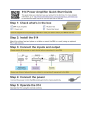
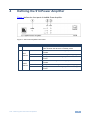
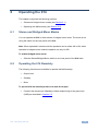
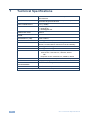
K R A ME R E LE CT R O N IC S L TD . USER MANUAL MODEL: 914 Power Amplifier P/N: 2900-300280 Rev 1 Contents 1 Introduction 1 2 2.1 Getting Started Achieving the Best Performance 2 2 3 3.1 Overview Energy Star 3 3 4 Defining the 914 Power Amplifier 5 5 5.1 5.2 5.3 5.4 Connecting the 914 Connecting the 914 Connecting the Remote Controls Connecting the Speakers Connecting a Balanced and Unbalanced Stereo Audio Input 7 7 8 9 10 6 6.1 6.2 7 Operating the 914 Stereo and Bridged Mono Modes Operating the 914 Remotely Technical Specifications 11 11 11 12 Figures Figure 1: 914 Power Amplifier Front Panel Figure 2: 914 Power Amplifier Rear Panel Figure 3: Connecting the 914 Power Amplifier Figure 4: Connecting Remote Control Switches to the 914 Figure 5: Connecting Speakers to the 914 Power Amplifier Figure 6: Balanced Stereo Audio Connection Figure 7: Unbalanced Stereo Audio Input Connection 5 6 8 8 9 10 10 914 – Contents i 1 Introduction Welcome to Kramer Electronics! Since 1981, Kramer Electronics has been providing a world of unique, creative, and affordable solutions to the vast range of problems that confront the video, audio, presentation, and broadcasting professional on a daily basis. In recent years, we have redesigned and upgraded most of our line, making the best even better! Our 1,000-plus different models now appear in 14 groups that are clearly defined by function: GROUP 1: Distribution Amplifiers; GROUP 2: Switchers and Matrix Switchers; GROUP 3: Control Systems; GROUP 4: Format/Standards Converters; GROUP 5: Range Extenders and Repeaters; GROUP 6: Specialty AV Products; GROUP 7: Scan Converters and Scalers; GROUP 8: Cables and Connectors; GROUP 9: Room Connectivity; GROUP 10: Accessories and Rack Adapters and GROUP 11: Sierra Products; GROUP 12: Digital Signage; and GROUP 13: Audio, and GROUP 14: Collaboration. Congratulations on purchasing your Kramer 914 Power Amplifier, which is ideal for the following typical applications: Presentation rooms and multimedia applications for local audio amplification Personal audio listening (for example, a PC and portable CD player) 914 - Introduction 1 2 Getting Started We recommend that you: Unpack the equipment carefully and save the original box and packaging materials for possible future shipment Review the contents of this user manual Use Kramer high performance high resolution cables. Use only the power cord that is supplied with this machine i 2.1 Go to http://www.kramerelectronics.com/support/product_downloads.asp to check for up-to-date user manuals, application programs, and to check if firmware upgrades are available (where appropriate). Achieving the Best Performance To achieve the best performance: Use only good quality connection cables (we recommend Kramer highperformance, high-resolution cables) to avoid interference, deterioration in signal quality due to poor matching, and elevated noise levels (often associated with low quality cables) Do not secure the cables in tight bundles or roll the slack into tight coils Avoid interference from neighboring electrical appliances that may adversely influence signal quality ! 2 Position your Kramer 914 away from moisture, excessive sunlight and dust This equipment is to be used only inside a building. It may only be connected to other equipment that is installed inside a building. 914 - Getting Started 3 Overview The Kramer 914 is a high performance power amplifier that accepts a balanced stereo audio input on a 5-pin terminal block and converts the signal into a differential stereo audio output for speakers on a 4-pin terminal block. The 914 Power Amplifier features: Input level sensitivity adjustment 10K Remote control Stereo and bridged mono modes Left and right channel monitoring LEDs The 914 Power Amplifier is housed in a Kramer 1/2U enclosure. 3.1 Energy Star The 914 Power Amplifier meets the ENERGY STAR audio specification and draws less than 1 watt while in standby mode; it offers a sleep mode, auto power-down, and meets the specified efficiency requirements. To comply with the Energy Star requirements the 914 provides the following operational modes: 1. On Mode—Where the 914 is connected to a mains power source, has been activated and is capable of providing amplification. The common terms “active”, “in-use” and “normal operation” also describe this mode. Active State—A state within On Mode in which the 914 provides amplification Standby State—A state within On Mode in which the 914 does not provide amplification 914 - Overview 3 2. Standby Mode—where the 914 is connected to a mains power source, is incapable of providing amplification, and offers the following user oriented or protective functions: It facilitates the activation of other modes (including activation of On Mode) by a remote switch (including remote, contact-closure switches), and timer The front panel’s information LEDs continuously display the status of the device The sensor-based functions function continuously. For purposes of this specification, Sleep Mode is defined as the time when the product is connected to a power source, does not produce sound, and is waiting to be switched to On Mode by a direct or indirect signal 3. Off Mode—where the product is connected to a mains power source, is not providing amplification, and cannot be switched into any other mode except by user actuation of a manual power switch. 4 914 - Overview 4 Defining the 914 Power Amplifier Figure 1 defines the front panel of the 914 Power Amplifier. Figure 1: 914 Power Amplifier Front Panel # Feature Function 1 ON LED Lights green when the device is powered on Lights red when the device is in standby mode 2 LEFT Channel 3 RIGHT Channel PROTECT LED Lights red when the left channel signal protection is activated CLIP LED Lights yellow when the left channel signal is clipping SIGNAL LED Lights green when there is a signal present on the left channel PROTECT LED Lights red when the right channel signal protection is activated CLIP LED Lights yellow when the right channel signal is clipping SIGNAL LED Lights green when there is a signal present on the right channel 914 - Defining the 914 Power Amplifier 5 Figure 2 defines the rear panel of the 914 Power Amplifier. Figure 2: 914 Power Amplifier Rear Panel # Feature 1 Function L+ L– G R+ R– 5-pin Terminal Block Connect to a balanced, stereo, analog audio source 2 LEVEL Trimmer Turn clockwise to increase the input level and anticlockwise to decrease the input level 3 L– L+ R– R+ 4-pin Terminal Block Connect to the speakers (see Section 5.2) STEREO BRIDGED MONO Switch Push switch up to operate in standard stereo mode; push switch down to operate in bridged mono mode (see Section 5.2) INPUT 4 SPEAKER OUT 5 6 REMOTE 7 V+ LEVEL GND Connect to the output level control STANDBY MUTE 5-pin potentiometer (10kΩ), and the remote Terminal Block Standby and Mute switches (see Section 5.2) ENABLE DISABLE Switch When the switch is up, the remote volume control is enabled; when the switch is down, the remote volume control is disabled Connect to the mains power Mains Power Unit Mains Fuse for protecting the 914 Switch for turning the device on and off 6 914 - Defining the 914 Power Amplifier 5 Connecting the 914 This chapter comprises the following sections: 5.1 Connecting the 914 (see Section 5.1) Connecting the remote controls (see Section 5.2) Connecting the speakers (see Section 5.3) Connecting the 914 i Always switch off the power to each device before connecting it to your 914. After connecting your 914, connect its power and then switch on the power to each device. To connect the 914 as illustrated in the example in Figure 3: 1. Connect the balanced, stereo audio source (for example, a multimedia player) to the INPUT 5-pin terminal block (see Section 5.4). 2. Connect the Speaker Out terminal block to a pair of speakers. Connect the left speaker to the L+ and L– pins, and the right speaker to the R– and R+ pins (in stereo mode). For bridged mono mode, see Section 5.3. Note: Do not ground the speakers. 3. Optional—Connect the GND, LEVEL and V+ pins on the 10V CONTROL terminal block connector to a remote 10kΩ volume control. 4. Optional—Connect the Standby and Mute pins to remote control switches (see Section 5.2). 5. Connect the supplied power cord to the 914 power socket and to the mains electricity (not shown in Figure 3). 6. Adjust the volume using the Level control on the rear panel. 914 - Connecting the 914 7 Figure 3: Connecting the 914 Power Amplifier 5.2 Connecting the Remote Controls You can operate the 914 remotely using switches connected to the rear of the device as shown in Figure 4. Figure 4: Connecting Remote Control Switches to the 914 8 914 - Connecting the 914 To connect a remote level control, (for example, the Kramer W-LM): Connect one side of the potentiometer to the V+ pin Connect the opposite side of the potentiometer to the GND pin Connect the wiper of the potentiometer to the Level pin To connect Mute and Standby switches: Connect one side of the Mute and Standby switches to V+ Connect the opposite side of the Standby momentary contact switch to the STANDBY pin Connect the opposite side of the Mute single pole single throw switch to the MUTE pin 5.3 Connecting the Speakers The 914 can be operated in either stereo or bridged-mono mode. Note: When operated in stereo mode the speakers can be either 4Ω or 8Ω; when operated in bridged-mono mode the speaker can only be 8Ω. Figure 5: Connecting Speakers to the 914 Power Amplifier To connect speakers to the 914 in stereo mode: Connect the L– and the L+ pins to the – and + terminals of the left speaker respectively Connect the R– and the R+ pins to the – and + terminals of the right speaker respectively 914 - Connecting the 914 9 To connect speakers to the 914 in bridged-mono mode: Connect the L+ and the R– pins to the + and – terminals of the speaker respectively 5.4 Connecting a Balanced and Unbalanced Stereo Audio Input This section illustrates how to wire: A balanced, stereo audio connection, see Figure 6 An unbalanced stereo audio input connection, see Figure 7 Figure 6: Balanced Stereo Audio Connection 10 Figure 7: Unbalanced Stereo Audio Input Connection 914 - Connecting the 914 6 Operating the 914 This chapter comprises the following sections: 6.1 Stereo and bridged-mono modes (see Section 6.1) Operating the 914 remotely (see Section 6.2) Stereo and Bridged Mono Modes You can operate the 914 in either stereo or bridged mono mode. The mode is set using the switch on the rear panel of the 914. Note: When operated in stereo mode the speakers can be either 4Ω or 8Ω; when operated in bridged-mono mode the speaker can only be 8Ω. To enable bridged-mono mode: 6.2 Slide the Stereo/Bridged Mono switch on the rear panel of the 914 down Operating the 914 Remotely The following functions are available to operate the 914 remotely: Output level Standby Mute To put the 914 into standby mode or to mute the output: Connect the relevant pin (Standby or Mute respectively) to the ground pin (GND) as described in Section 5.2 914 - Operating the 914 11 7 Technical Specifications INPUT: 1 balanced stereo +4dBu/10kΩ on a 5-pin removable terminal block OUTPUT: 1 stereo or bridged mono speaker output on a 4-pin removable large terminal block INPUT SENSITIVITY: 0.3V (–10dBu) OUTPUT POWER: 2 x 100W @ 4Ω 2 x 50W @ 8Ω 1 x 200W @ 8Ω BTL AMPLIFIER TYPE: Class D MAXIMUM VOLTAGE GAIN: 22.7dB BANDWIDTH (-3dB): 20Hz to 20kHz S/N RATIO: –70dB @ 14dBu amplification CONTROLS: Screw trimmer for line input sensitivity; Remote 10k trimmer; Contact-closure controls for mute and standby AUDIO THD + NOISE: 0.05% @ 75W RMS @ 4Ω 6.67kHz AUDIO 2nd HARMONIC: 0.08% @ 75W RMS @ 4Ω 6.67kHz POWER SOURCE: See label by power socket on rear panel of unit: USA version: 100-120V AC, 50/60Hz, 360VA OR European version: 200-240V AC, 50/60Hz, 420VA DIMENSIONS: 21.2cm x 22.8cm x 4.3cm (8.35" x 8.98" x 1.69") W, D, H WEIGHT: 1.0kg (2.2lbs) approx. INCLUDED ACCESSORIES: Power cord, mounting bracket OPTIONS: RK-3T 19” rack adapter Specifications are subject to change without notice at http://www.kramerelectronics.com 12 914 - Technical Specifications For the latest information on our products and a list of Kramer distributors, visit our Web site where updates to this user manual may be found. We welcome your questions, comments, and feedback. Web site: www.kramerelectronics.com E-mail: [email protected] ! P/N: SAFETY WARNING Disconnect the unit from the power supply before opening and servicing 2900- 300280 Rev: 1