1
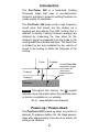
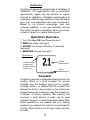
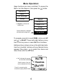
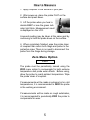
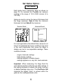
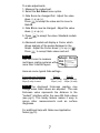
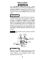
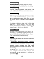
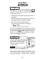
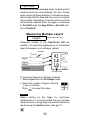
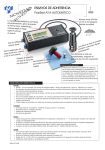
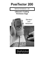
PosiTector 200
INSTRUCTION MANUAL v. 2.0
Ultrasonic Coating
Thickness Gage
Standard
and
Advanced
Simple. Durable. Accurate.
Introduction
The PosiTector 200 is a hand-held Coating
Thickness Gage that uses a non-destructive
ultrasonic principle to measure coating thickness on
a wide variety of substrates.
The PosiTector 200 probe emits a high frequency
sound pulse that travels into the coating via a
coupling gel and reflects from ANY surface that is
different in density. Coating thickness readings are
obtained by measuring the time taken for the
ultrasonic signal to propagate from the probe to the
coating/substrate interface and back. The travel time
is divided by two and multiplied by the velocity of
sound in the coating to obtain the thickness of the
coating.
Probe
Couplant
The PosiTector 200
interprets the largest
“echo” within the
Gates as the
coating/substrate
echo.
Coating 1
Coating 2
Substrate
NOTE: Throughout this manual, the
symbol
indicates more information about the particular topic
or feature is available on our website.
Go to: www.defelsko.com/manuals
Power-up / Power-down
The PosiTector 200 powers-up when any button is
pressed. To preserve battery life, the Gage powersdown after approximately 3 minutes of no activity. All
settings are retained.
2
Certification
All probes or gages are shipped with a Certificate of
Calibration. For organizations with re-certification
requirements, gages may be returned at regular
intervals for calibration. DeFelsko recommends that
customers establish gage calibration intervals based
upon their own experience and work environment.
Based on our product knowledge, data and
customer feedback, a one year calibration interval
from either the date of calibration, date of purchase,
or date of receipt is a typical starting point.
Operation Overview
1. Turn the Gage ON (see Power-Up pg.2)
2. ZERO the probe (see pg.5)
3. ADJUST to a known thickness, if necessary
(see pg.8)
4. MEASURE the part (see pg.5)
Typical Display:
1
Current
Measurement
Indicates Gage is
in single layer
mode (Advanced
models only)
Unit of
Measurement
Couplant
Couplant is required to propagate ultrasound into the
coating. Water is a good couplant for smooth
coatings. Use the supplied glycol gel for rougher
coatings. While it is unlikely that the couplant will
damage the finish or leave a stain on the surface, we
suggest testing the surface by using the couplant on
a sample. If testing indicates that staining has
occurred, a small amount of water can be used
instead of couplant. Consult the Material Safety Data
Sheet available on our website and your coating
supplier if you suspect the couplant may damage the
coating. Other liquids such as liquid soap may also
be used.
3
Menu Operation
Gage functions are menu controlled. To access the
Menu, turn the Gage on, then press the
button.
Memory
Zero
Cal Settings
Setup
*
Graphics on Advanced
models only
Current selection is displayed
with darkened background
Reset
Graphics*
Gage Info
Units
Set Clock
Language
To navigate, press (-) to scroll DOWN, (+) to scroll UP
and
to SELECT. Press both (-)(+) buttons at any
time to exit any menu or select Exit from the Menu.
List boxes have a down arrow on the right-hand side.
Use the (-) and (+) buttons until your desired choice
appears, then press
to select this choice and
move focus onto the next item.
“List“ box
a “tick” indicates this square
box has been selected
“Radio” buttons. Only one
can be selected at a time.
“Focus” is currently at this
unselected (empty) Radio button
4
How to Measure
1. Apply couplant to the surface of your part.
2. After power-up, place the probe FLAT on the
surface and press down.
3. Lift the probe when you hear a
double BEEP or see the green indicator light blink. Measurement result
is displayed on the LCD.
A second reading may be taken at the same spot by
continuing to hold the probe down on the surface.
4. When completely finished, wipe the probe clean
of couplant then return both Gage and probe to the
protective case. There is no need to disconnect the
probe from the Gage during storage.
Zero Menu Option
Zero
The probe must be periodically zeroed using the
ZERO menu option to compensate for both extreme
temperature and probe wear effects. Before using,
allow the probe to reach ambient temperature. Wipe
the probe clean of couplant.
If measurements will be made in extreme hot or cold
temperatures, it is recommended to ZERO the probe
in the working environment.
If measurements will be made on rough substrates,
it is recommended to periodically ZERO the probe to
compensate for wear.
5
Set Gates Option
Set Gates
Each probe has a measuring range as shown on
page 19. For example the C probe can measure
coatings in the range of 50 to 3800 microns (2 to
150 mils).
Gates are used to narrow the range of thickness that
the Gage examines. Gate A sets the minimum
thickness limit and Gate B the maximum.
Advanced Model
Standard Model
For most applications the default Gate values do not
have to be adjusted. But some conditions may exist
in the user's application that cause the Gage to
display very low or non-repeatable readings. These
conditions include…
·rough or textured coatings
·hard (dense) coatings
·coatings applied in multiple layers
·coatings applied on a very thin, hard substrate
Important: When measuring, the Gage finds the
most distinct interface within the two Gate settings. If
the coating thickness is outside this range, incorrect
or dashed readings may occur. The PosiTector 200
interprets the largest “echo” or echoes within the
gates as the coating/substrate echo.
6
To make adjustments:
1. Measure the coated part.
2. Select the Set Gates menu option.
3. Gate A can be changed first. Adjust the value
down (-) or up (+).
Press
to accept the value and to move to
Gate B.
4. Gate B can now be changed. Adjust the value
down (-) or up (+).
5. Press
will exit.
to accept the value. Standard models
6. Advanced models will display a Cursor which
allows analysis of the peaks displayed in the
Graph. Adjust the Cursor down (-) or up (+).
Press
to accept Gate values and exit.
NOTE:
Use the Cursor to measure
multi-layer coating systems with
more than 3 distinct layers.
Here are some typical Gate settings...
Expected paint thickness
500um (20 mils) on concrete
50µm (2 mils) on wood
Gate A
Gate B
130µm (5 mils) 1000µm (40 mils)
25µm (1 mil)
250µm (10 mils)
NOTE: The displayed thickness reading may
change when Gate values are adjusted. The new
thickness value represents the distance to the
"loudest" interface within the new A/B Gate values
(see pg.2). This handy feature makes it easy to
ignore other measurements such as surface
roughness.
For additional help with Gates see Application
Notes (pg.15)
7
Adjust Thickness Option
Adj Thickness
Select a reference standard of material as close as
possible in composition to the intended application.
For best results, the thickness of the reference standard should be equal to or slightly greater than the
thickness of the coating to be measured.
1. Apply a drop of couplant onto the reference standard.
2. Measure the reference standard.
3. Lift the probe. Select the Adj Thickness menu
option.
4. Adjust the display down (-) or up (+) to the
reference standard thickness.
5. Press
to store the adjustment. Standard
models will exit.
6. Advanced models with more than 1 layer selected
will continue to the next layer. Adjust the thickness
(step 4) and store the adjustment by pressing
.
When all layers have been adjusted, the gage will
exit the Adj Thickness option.
Note: A Reset (pg.11) will restore factory settings.
8
Memory Mode
Memory
The PosiTector 200 can record 10,000
measurements in up to 1000 groups (batches) for
on-screen statistical purposes, for printing to an
optional IR printer, or for downloading to a personal
computer using optional PosiSoft software and USB
cable.
New Batch
-closes any currently opened batch and creates a
new batch name using the next higher number. For
example, if only Batch 1 and Batch 3 exist, then Batch
4 would be created and made the current batch.
Statistics are displayed and each measurement will
now be simultaneously shown on the display and
stored into this new batch. On screen statistics are
immediately updated with each measurement. New
batch names are date stamped at the time they are
created.
Shortcut: When a batch is open, create a new batch
by pressing (+)
Mean
(average)
Standard
Deviation
Max and Min
measurement
Last
reading
Current
Batch
No. of
measurements
Open
-selects a previously created batch name to open
and make current. If it contains measurements, onscreen statistics will immediately reflect values
calculated from this batch.
9
Close
-stops the recording process, closes the current
batch, and removes the statistics from the display.
Delete
-removes a batch completely from memory. The
name is deleted and all measurements are erased.
View
-lists all readings on the display from the current or
most recently used batch. It begins by showing the
last 10 measurement values. Scroll using the (-) or
(+) buttons. Hold for 1 second to scroll a page at a
time.
To change or delete a value, scroll to that value
(align the “+” symbol beside it) then either take
another measurement to change it, or press
to
delete it or exit. Statistics are updated.
Print
-prints all stored measurements to the optional IR
printer or to a PC’s default Windows printer via the
optional USB cable and PosiSoft software. Press
(-)(+) simultaneously to cancel printing.
NOTE:
Remove the last reading from the current open batch
by pressing (-).
Downloading Measurements Stored in Memory
Measurements stored in the Gage's memory (in
batches) can be downloaded to a computer using
optional PosiSoft software and USB cable.
Measurements are not erased from memory after
downloading.
PosiSoft® allows entry of notes and annotations,
prints histograms and basic charts, manages data,
and readings can be exported to a document or
spreadsheet.
10
Setup Menu
Setup
Reset
Reset restores factory settings and returns
the Gage to a known, out-of-the-box
condition. It is handy when you want to “start all over”
The following occurs:
- all batches are closed and stored measurements
are erased.
- calibration adjustments are cleared and returned
to the Gage’s factory calibration settings.
- Gates are returned to default settings.
- menu setting are returned to the following:
Memory = OFF
Graphics = OFF (Advanced models only)
A more thorough Reset can be performed by holding
the (+) button when the Gage is powered down until
the Reset symbol
appears. It performs the same
function as a menu Reset with addition of Units =
microns, and Language = English.
Graphics
Advanced models only
The right hand side of the screen
can be used to display a graphical
representation of the ultrasonic
pulse as it passes through the
coating system.
Shortcut: Press the (+) to toggle Graphics On/Off
(shortcut is active when Memory is off)
As the probe is depressed and the ultrasonic pulse
travels through the coating system, the pulse
encounters changes in density at the interfaces
11
between coating layers and between the coating and
the substrate.
These interfaces are depicted by a "peak". The
greater the change in density the higher the peak.
The more gradual the change in density, the greater
the width of the peak. For example, two coatings
layers made of essentially the same material and
"blended" would result in a low, wide peak. Two
materials of very different density and a well-defined
interface would result in a high, narrow peak.
The PosiTector 200 Advanced chooses the highest
of peaks when trying to determine coating layer
thickness. For example, if the number of layers is set
to 3, the 3 highest peaks between the A & B Gates
are selected as the interfaces between these layers.
The peaks that the Gage selected are indicated by
black triangle arrows.
The top (A) and bottom (B) Gate values (pg.6) are
displayed as two horizontal lines at the top and
bottom of the graphics area. Their current values are
shown to the right of each line. Gate A, the minimum
limit, is at the top. Gate B, the maximum limit, is at
the bottom. Echoes or peaks (thickness values)
outside these Gates are ignored. Gate values are set
and modified using the Set Gates menu option.
This Graphics display can be manipulated with the
Set Gates menu option. In addition to being able to
adjust the Gate values, a Cursor can be positioned
anywhere between the two Gate values to
investigate other peaks.
Units
This menu button converts the display and all stored
readings from mils to microns or vice versa.
12
Set Clock
All batches are date-stamped when created, and all
measurements are time-stamped (24 hour format)
when stored into these batches. It is therefore important to keep both the date and time current using this
menu button. Alternatively, the date and time can be
automatically updated when the gage is connected
to PosiSoft using the Gage Utilities -> Set Clock function in PosiSoft.
Measuring Multiple Layers
Advanced models only
Layers
Advanced models of the PosiTector 200 are
capable of numerically displaying up to 3 individual
layer thicknesses in a multi-layer system.
Couplant
Probe
Layer 1
Layer 2
Layer 3
Substrate
Total thickness
To setup the Gage for multi-layer coatings:
1. Select Layers from the Cal Settings menu.
2. Select the number of layers using the
(-) and (+) buttons.
Press
to accept the value.
NOTE:
Before setting up the Gage for multi-layer
measurement, it is recommended that you first take
measurements in single layer mode and interpret the
results using the Graphics option (see pg.11)
13
Available Options
A variety of accessories are available to help you get
the most from your PosiTector 200 coating
thickness gage.
Calibration, Verification and
Adjustment
Three steps ensure best accuracy…
1. Calibration - typically done by the manufacturer
or a qualified lab
2. Verification of Accuracy - as done by the user
3. Adjustment - to a known thickness
Calibration
Calibration is the controlled and documented
process of measuring traceable calibration
standards and verifying that the results are within the
stated accuracy of the Gage. Calibrations are
typically performed by the Gage manufacturer or by
a certified calibration laboratory in a controlled
environment using a documented process.
Verification
Verification is an accuracy check performed by the
user using known reference standards. A successful
verification requires the Gage to read within the
combined accuracy of the Gage and the reference
standards.
Adjustment
Adjustment, or Calibration Adjustment, is the act of
aligning the Gage's thickness readings to match that
of a known reference sample in order to improve the
accuracy of the gage on a specific coating. (pg.8)
14
The PosiTector 200 is factory calibrated. But in
order for it to take accurate thickness measurements
of a particular material it might be necessary to
adjust the gage for that material. To determine if an
adjustment is necessary for your application,
measure a sample of known thickness of the coating
material to be measured. If the average of a series
of measurements is not close to the expected
thickness, adjust to the expected thickness.
Samples should be flat, smooth and as thick or
thicker than the maximum expected thickness of the
piece to be tested.
Application Notes
The PosiTector 200 uses an ultrasonic principle to
measure coating thickness of most coatings on most
substrates. An ultrasonic signal is a very high
frequency sound wave. Like the echoes you hear
when you shout in a large hall or canyon the
PosiTector 200 listens for echoes from acoustic
boundaries within your application.
The PosiTector 200 probe emits a high frequency
sound pulse that travels into the coating via a
coupling gel and reflects from ANY surface that is
different in density. Coating thickness readings are
obtained by measuring the time taken for the
ultrasonic signal to propagate from the probe to the
coating/substrate interface and back. The travel time
is divided by two and multiplied by the velocity of
sound in the coating to obtain the thickness of the
coating. The strength of the reflected signal from the
coating/substrate interface determines the ability of
the instrument to measure the thickness of the
coating. Since most applications are not
homogeneous the gage will "hear" many echoes
when placed on a coating/substrate. The instrument
"hears" ALL reflections within the measurement
15
limits of the gage and assumes the largest “echo” is
the coating/substrate echo (single coating
applications only). Adjustable measurement Gates
have been provided for the user to force the
instrument to ignore echoes from unwanted
boundaries within the sample. Several examples
below help to illustrate the use of Gates for specific
applications.
Measurement of coatings with rough surfaces.
When rough coatings are measured, the gage
typically identifies the thickness from the top of the
coating peaks down to the substrate (#1). Couplant
fills the voids between the probe and the coating (#2)
creating an additional interface. If echoes from the
couplant/coating interface (#2) are stronger than the
coating/substrate interface (#1), an adjustment
(increase) of Gate A may be required for the gage to
display the weaker (#1) echo.
Probe
Coating
#1
Couplant
#2
Substrate
Measurement of dense (hard) coatings.
A significant echo occurs at the probe/coating
interface. The relative strength of this echo
compared to the coating/substrate echo requires that
Gate A be increased.
Measurement of total thickness in multi-layer
coating applications.
Multiple coating/coating/substrate interfaces may
generate several echoes. The user may need to
adjust Gates to ignore echoes from coating/coating
interfaces.
16
Troubleshooting
Gage does not turn on
Make sure the + and - battery terminals are positioned properly and that fresh Alkaline batteries are
being used.
Gage powers up but fails to stay on
Replace batteries with fresh Alkaline batteries. If
problem persists return Gage for service.
Gage readings are much lower than expected
Gage may be measuring surface roughness. Raise
the value of Gate A. See pg.6
Gage readings are much higher than expected
Gage may be measuring both the coating and
substrate. Lower the value of Gate B. See pg.6
Gage does not yield accurate or consistent
results
See the Set Gates (pg.6) and Adjustment (pg.8)
sections to ensure the gage has been optimized for
your application. Check the Gage on traceable
standards.
Gage displays an error message while attempting probe ZERO
Make sure to hold the probe
ZERO FAILED 1
in the air and ensure the
probe is free of couplant. If
OK
problem persists, note the
error message and contact our technical support
department.
17
Changing The Batteries
The battery icon
displays a full bar with fresh
alkaline batteries installed. As the batteries weaken,
the bar will be reduced. When the battery icon is low
, the Gage can still be used, but the batteries
should be changed at the earliest opportunity. USE
ONLY “AAA” ALKALINE BATTERIES. Nickel-cadmium and
nickel-metal hydride rechargeable batteries will work
but the Gage may appear to have weak batteries.
To retain all user settings and stored memory readings, only replace the batteries after the Gage has
automatically powered-down.
Returning for Service
Before returning the Gage for service…
1.Install new Alkaline batteries in the proper
alignment as shown within battery compartment.
2.Examine the probe tip for dirt or damage.
3.Perform a Reset (pg.11) and a Zero (pg.5)
4.Place a plastic shim onto a hard surface (i.e. glass)
and attempt a measurement. (see pg.5)
If you must return the Gage for service, describe the
problem fully and include measurement results, if
any. Be sure to also include the gage, probe, your
company name, company contact, telephone
number and fax number or email address.
Website: www.defelsko.com/support
Technical Data
Conforms to: ASTM D6132 and ISO 2808
Gage body dimensions:
(146 x 64 x 31 mm) 5.75" x 2.5" x 1.2"
Temperature Range: 0 to 40°C (+32° to +104°F)
18
Probe
Measuring Range*
B
13 - 1000 microns (0.5 - 40 mils)
C
50 - 3800 microns (2 - 150 mils)
*Range limits apply to polymer coatings only.
Accuracy: ± (2 microns
± (0.1 mils
+ 3% of reading)
+ 3% of reading)
Warranty
DeFelsko fully warrants its products against defects
in workmanship or materials under normal use for a
period of two years from date of purchase. In the
event that an instrument is believed to be defective,
return the product with proof of purchase to your
dealer. If upon DeFelsko’s inspection of the
instrument, it is determined in our sole discretion that
the returned instrument is defective as to
workmanship or material, the instrument will be
repaired or replaced at DeFelsko’s sole option.
In no event shall DeFelsko be liable for any indirect,
special, incidental or consequential damages.
The warranty is voided if the Instrument has been
opened.
Data subject to change without notice.
19
www.defelsko.com
© DeFelsko Corporation USA 2006
All Rights Reserved
This manual is copyrighted with all rights reserved and may not be reproduced or
transmitted, in whole or part, by any means, without written permission from
DeFelsko Corporation.
DeFelsko, PosiTector and PosiSoft are trademarks of DeFelsko Corporation registered in the U.S. and in other countries. Other brand or product names are trademarks or registered trademarks of their respective holders.
Every effort has been made to ensure that the information in this manual is accurate. DeFelsko is not responsible for printing or clerical errors.