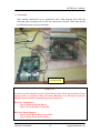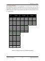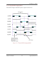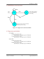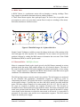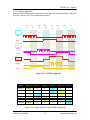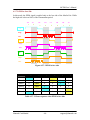
1
MCDB User’s Manual Motor Control Daughter Board Revision 3.0 User’s Manual Revision History Date 09/08/2006 30/12/2006 Ishnatek Confidential Version 1.0 2.0 Description Author Revision 1.0 Shivachandra Javalagi Preliminary Document Ishnatek Systems Revision 3.0 Shivachandra Javalagi Final Document Ishnatek Systems -1- [email protected] MCDB User’s Manual Ishnatek Confidential -2- [email protected] MCDB User’s Manual CONTENTS 0. 1. 2. 3. 4. 5. 6. 7. 8. 9. 10 Before Starting Introduction Contents and System Requirements Connection steps and Precaution 3.1 Connection steps 3.2 Connection Details 3.3 Precaution Operational Settings Detailed Board Description and Usage 5.1 Block Diagram 5.2 Board’s picture 5.3 Status LED’s 5.4 Jumpers 5.5 Switches 5.6 Connectors Detailed Design Description 6.1 Stepper Motor 6.1.1 Stepper Drive 6.1.2 Stepper control state machine 6.1.3 Stepper speed calculation 6.2 BLDC Drive 6.2.1 Sensored Drive – HALL 6.2.2 Sensorless Drive – BEMF 6.2.3 PWM Frequency Speed control 6.2.4 Speed Control 6.2.5 Fault Protection 6.2.6 Commutation 6.2.7 PWM Modes 6.2.7.1 PWM to High Side 6.2.7.2 PWM to Low Side 6.2.7.3 PWM to Both Sides 6.2.7.4 Complementary PWM 6.2.8 BEMF Sensing Circuit 6.2.9 BLDC Control State Machine 6.3 Brushed Drive Software Fusion Software Control Register Map Appendix 9.1. APPENDIX A – AFS600 FG256 Pin List 9.2. APPENDIX B- Motor Specifications & Connections 9.3. APPENDIX C- Board Schematics Contact Details/Support Ishnatek Confidential -3- 4 5 6 7 7 9 12 13 14 14 15 17 18 21 23 25 25 26 30 30 31 31 33 35 35 35 38 39 40 41 42 43 45 46 47 55 59 59 62 67 76 [email protected] MCDB User’s Manual 0.0 Before Starting 0.1 Safety Warnings 0.1.1 General In operation, the Motor Control Kit has un-insulated wires, moving or rotating parts as well as hot surfaces. In case of improper use, wrong installation or mal-operation, there is danger of serious personal injury and damage to property. All operations, installation and maintenance are to be carried out by skilled technical personnel (national accident prevention rules must be observed). When the Motor Control board is supplied with voltages greater than 24 V AC/DC, all of the board and components must be considered “hot”, and any contact with the board must be avoided. The operator should stay away from the board as well (risk of projection of material in case of components destruction, especially when powering the board with high voltages). The rotating parts of motors are also a source of danger. Never try to stop the motor by holding the rotating shaft by hand. The Motor Control Kit contains electrostatic sensitive components which may be damaged through improper use. 0.1.2 Intended Use The ISH-ACT-MCK Starter Kit is made of components designed for demonstration purposes and must not be included in electrical installations or machinery. Instructions about the setup and use of the ISH-ACT-MCK Starter Kit must be strictly observed at all times. 0.1.3 Operation After disconnecting the board from the voltage supply, several parts and power terminals must not be touched immediately because of possible energized capacitors or hot surfaces. 0.1.4 Important Notice to Users While every effort has been made to ensure the accuracy of all information in this document, Ishnatek Systems and Actel assumes no liability to any party for any loss or damage caused by errors or omissions or by statements of any kind in this document, its updates, supplements, or special editions, whether such errors are omissions or statements resulting from negligence, accident, or any other cause. 0.2 Required Skills In order to profitably use the ISH-MCDB-R3 Motor Control Starter Kit, you should be acquainted with several skills, ranging from hardware design to software design. In particular, you should possess the knowledge about Electrical Motors and FPGA Programming. Ishnatek Confidential -4- [email protected] MCDB User’s Manual 1.0 Introduction: Features: • Supports o Stepper Motor (4-Wire, 5-Wire as well as 6-Wire Configuration) Full Step / Half Step Mode Micro Step Mode ( Sinusoidal / Trapezoidal Option) 8 / 16 / 32 Microsteps o Brushless DC (BLDC) Motor (Provision for 4- One Phase or 2 –Two Phase or 1 – Three Phase OR 1 – Four Phase BLDC Motor) Sensored Drive • Using Hall Effect Sensors provided on Motors Sensorless Drive • Using on board comparators OR • Using Fusion ADC threshold flags o Brushed Drive Support One Brushed Motor with Direction/Speed Control • Direction Control – Clockwise or Counterclockwise Rotation • Basic Functions Start Stop Step ( Full or Half Stepping in case of Stepper Motor) RPM+/RPM- (Increase/Decrease RPM) Analog/Digital Control Features • Four Acceleration Settings for various motor types Fast (208 milliseconds) Medium High (312 milliseconds) Medium Low (520 milliseconds) Slow (3.74 seconds) • Support Four PWM Modes PWM on high side of Mosfet Bridge PWM on low side of Mosfet Bridge PWM on both sides of Mosfet Bridge Complementary through Mosfet Bridge (BETA –Feature) • Hardware/Software Control Access to all above features through keys/switches on board Equivalent controls are provided also through software Software Interface using on-board USB-to-RS232 bridge • High Output Current up to 10A • Over Current/Over Temperature Protection through Shutdown Pin of the Mosfet Driver. Ishnatek Confidential -5- [email protected] MCDB User’s Manual 2. Contents and System Requirements Motor Control Daughter Board – Rev 3.0 Requirements: o Fusion Starter Kit (AFS600FG256ES) (Not Provided) o 40 Pin FRC Connector (To Fusion Starter Kit, Provided) o 12 Pin Straight Connector (To Fusion Starter Kit, Provided) o 4 Pin Straight Connector (To Fusion Starter Kit, Provided) o Baud Rate Select Cable (to Fusion Starter Kit, Provided) o BLDC Motor – Maxon EC-45 Flat (Provided - Appendix B for Details) o Stepper Motor – Hybrid Stepping Motor 14HY5401 (Provided - Appendix B for Details) o Motor and Reference Power Supply (Dual Output) (Provided) 12V, 5A (Motor Power Supply) 12V, 2A (Reference Power Supply) Software Requirements: o USB Cable (Provided) o Motor Control Software and USB Drivers (Provided) o Operating System - Windows XP or Higher Required Fusion STP Files (Provided) There are 2 versions of STP files available depending on the feature set as described below o mcdb_rev3_adc_drive.stp (This version does not support temperature and current sense features) o mcdb_rev3_ts_cs.stp (This version does not support BEMF drive using Fusion ADC) Apart from the above differences both version supports all the other features as described in the introduction. Ishnatek Confidential -6- [email protected] MCDB User’s Manual 3. Connection steps and Precaution 3.1 Connection steps Please follow the steps carefully in order to avoid damage to Fusion Board: Make sure the power to Fusion Kit and the Motor Control Kit are OFF. 3.1.1. Important Pre-Connection Checks: Make sure the AC input voltage switch on Kit is set to 110V (If not open the back lid of the kit and change it to 110V). Don’t Plug the Power Supply cord in yet. 3.1.2. Fusion Starter Kit Setup: Remove the following short-links on the Fusion Starter Kit, JP51, JP49, JP68, JP62, JP34, JP30 and JP37 3.1.2.1 RPM Control using Analog Potentiometer: A Potentiometer connected to Pin AV0 and to Fusion Pin ‘M6’ (On the Fusion Kit) can be used to control the speed when in analog control mode. 3.1.2.2 Connections for BEMF drive using Fusion ADC (If Fusion Kit is programmed with mcdb_rev3_adc_drive.stp) Remove Jumpers JP34 (‘M9’), JP30 (‘N7’) and JP37 (‘N9’) on Fusion Board Daughter Board Checks: • JP14, JP15, JP16 and JP17 on daughter board are closed – Scaled Motor Voltages • Pin 12 of J5 on daughter board connects to Fusion pin ‘M9’ by removing jumper ‘JP34’ on FUSION board. • Pin 11 of J5 on daughter board connects to Fusion pin ‘N7’ by removing jumper ‘JP30’ on FUSION board. • Pin 10 of J5 on daughter board connects to Fusion pin ‘N9’ by removing jumper ‘JP37’ on FUSION board . CABLE D – ( 4 – Open single Leads) (Orange left unconnected) Wire From Daughter Board Pin 12 of J5 (PH_A_BEMF) Pin 11 of J5 (PH_B_BEMF) Pin 10 of J5 (PH_C_BEMF) Ishnatek Confidential Color Code (CABLE - D ) Black Fusion Pin Brown N7 Red N9 -7- M9 [email protected] MCDB User’s Manual 3.1.2.3 Connections for current sensing: (If Fusion Kit is programmed with mcdb_rev3_ts_cs.stp) Remove Jumpers JP51 and JP49 on Fusion Board Daughter Board Checks: • JP20 and JP21 on daughter board are closed – Current Sense • Pin3 of J6 (VM_CS_OUT) on daughter board connects to Fusion Pin ‘M7’ by removing jumper JP51 on Fusion Board (Pin 2 of JP51) • Pin 4 of J6 (VM_LOW_OUT) on daughter board connects to Fusion Pin ‘P6’ by removing jumper JP49 on FUSION board (Pin 2 of JP49) Wire From Daughter Board Pin3 of J6 Board Pin Names VM_CS_OUT Color Code (CABLE - C) Brown Pin 4 of J6 Fusion Pin M7 (Pin 2 of JP51) VM_LOW_OUT Black P6 (Pin 2 of JP49) There is sense resistor Rs (10 milliohm) provided on the low side of the power drive. The current that flows through this sense resistor is discontinuous as the signal is chopped at the PWM frequency. The current flows during the ON time of the power stage and is zero during the OFF time. If you need to measure average current you will need to create your own hardware. This feature is not supported on the daughter board. 3.1.2.4 Connections for Temperature Sensing: (If Fusion Kit is programmed with mcdb_rev3_ts_cs.stp) Remove Jumpers JP68 and JP62 on Fusion Board Daughter Board Checks: • JP18 and JP19 on daughter board are closed – Temperature Sense • Pin 1 of J6 (T_RTN) on daughter card connects to Fusion pin ‘R12’ by removing jumper ‘JP62’ on FUSION board. (Pin 2 of JP62) • Pin 2 of J6 (T_SIG) on daughter card connects to Fusion pin ‘T12’ by removing jumper ‘JP68’ on FUSION board. (Pin 2of JP68) Wire From Daughter Board Pin1 of J6 Board Pin Names T_RTN Color Code (CABLE - C) Orange Pin 2 of J6 Fusion Pin R12 (Pin 2of JP62) T_SIG Red T12 (Pin 2of JP68) Note that the temperature sensing method used is quite susceptible to Noise. For higher accuracy it is necessary to use high resolution temperature sensors which are not susceptible to noise. To filter out the noise connect a capacitor of value 10nF between Pins R12 and T12 of fusion board. Ishnatek Confidential -8- [email protected] MCDB User’s Manual 3.2 Connection Details : 3.2.1 Connect the 40 Pin Connector – Pin1 should match on the Fusion Side and the Board side. This cable does not have polarization and it could go in either way, hence it is very important that the marking should be matched perfectly else this would cause damage to the board. A ‘Silver’ colored dot indicates Pin 1 on the connector. Make sure these match perfectly before turning on the Board (Warning: You could blow up the board if this is not done right) Black - Pin 40 and Dark Brown is Pin 1 Pin 1 of 40 Pin Cable goes to Pin 1 of J4 on Motor Control Board Side (Match the Silver Dot for Pin 1 on both sides Pin 1 of 40 Pin Cable goes to Pin 1 of J13 on Fusion Side (Match the Silver Dot for Pin 1 on both sides 3.2.2 The extra 8-wire connector (CABLE - D) should be connected to Fusion board as per table below. Wire from Wire to 10-way DIP on daughter card FUSION board Ishnatek Confidential Color Brown Yellow Green Blue Purple Gray White Black Signal name MST_SC_OR_PWM PWM_freq_sel[1] PWM_freq_sel[0] NO_MSTP_OR_BL_MD[1] NO_MSTP_OR_BL_MD[0] Acceleration time[1] Acceleration time[0] Stepper_range -9- Dip FUSION switch pin pin no. 3 10 9 8 7 6 5 4 K16 J14 J15 H12 H14 H16 G11 G14 [email protected] MCDB User’s Manual 3.2.3 Baud Rate Selection: The baud rate wires may be left unconnected, they have internal pull-ups and have been programmed to 9600 baud rate. If you want to change the baud rate for serial communication then you can connect these as per the data sheet that follows. Keep same baud rate setting for hardware as well as software. Wire From Wire To Color Code (Baud Rate Select Cable) Fusion Pin Baudclock reg [2] As per baud rate selection table below GND or VDD Orange H11 Yellow H13 White H15 Baudclock reg [1] Baudclock reg [0] 3.2.4 Baud Rate selection table Baudclock reg [2] Orange 0 0 0 0 1 1 1 1 Baudclock reg [1] Yellow 0 0 1 1 0 0 1 1 Baudclock reg [0] White 0 1 0 1 0 1 0 1 BAUDRATE 1220 2440 4880 9600 19200 Reserved Reserved Reserved For more macro view you may look at additional pictures available in Appendix D. Ishnatek Confidential - 10 - [email protected] MCDB User’s Manual 3.2.5 Motor Connections You can either connect a Stepper Motor (4 –Wire) or a BLDC Motor (3 Phases) to the back panel provided on the kit as below to the back: 3.2.5.1 Stepper Motor Connections: (CABLE-F, 4 Wires) Phase ‘A’ Original wire/leads on the motor Red Phase ‘B’ Blue Phase ‘C’ Green Phase ‘D’ Black Motor Connections MOT_A (To Back Panel) MOT_B (To Back Panel) MOT_C (To Back Panel) MOT_D (To Back Panel) 3.2.5.2 BLDC Motor Connections: (CABLE-E, 3 wires) Color Code Phase ‘A’ Red Phase ‘B’ Blue Phase ‘C’ Green Motor Connections MOT_A (To Back Panel) MOT_B (To Back Panel) MOT_C (To Back Panel) Note: Only one motor can be connected to the back panel. For sensorless operation it is not necessary to remove the Hall connections. Ishnatek Confidential - 11 - [email protected] MCDB User’s Manual 3.3 Precaution After making connections as per instructions and wiring diagram given take the following steps for turning ON or OFF the connections to the kit. These steps should be followed strictly to protect the boards. These 4 wires may be left unconnected WARNING! In order to protect the I/O’s of the Fusion Part a proper Power up and Power Down sequence has to be followed. This will ensure that there is no back-power from the daughter board to fusion board and hence protect the I/O’s. Kit Power Up Sequence: Step 1: Power up Fusion Board Step 2: Power up Motor Control Kit Kit Power Down Sequence: Step 1: Power Down Motor Control Kit Step 2: Power Down Fusion Board Ishnatek Confidential - 12 - [email protected] MCDB User’s Manual 4 Operational Settings 4.1 BLDC Acceleration Settings: In the current setup, for Maxon EC45 Flat, use MEDIUM HIGH or MEDIUM LOW setting for acceleration. 4.2 BLDC Motor using Analog Drive: While running the BLDC motor in Sensorless Mode and using Analog Drive, make sure the Potentiometer (R50 on the Fusion Kit connected to AV0 or pin ‘M6’) is at its maximum (The LED’s on Fusion Kit, D1 to D8 will reflect the value of the Potentiometer setting, the value will be Hex FA, D8- MSB and D1 - LSB ) In case of sensored drive, this Potentiometer can be at any position and the motor will start and run at the speed set by the Potentiometer. 4.3 Stepper Motor using Analog Drive: In the case of Stepper there are only 16 steps for speed control. The 4 MSB bits of the analog ADC outputs as reflected by the LED’s D4-D1 control the divide by N ratio of the applied frequency to the stepper drive circuit. While running the stepper motor using Analog Drive, make sure the Potentiometer (R50 on the Fusion Kit connected to AV0 or pin ‘M6’) is at its maximum (The LED’s on Fusion Kit, D4 to D1 will reflect the value of the Potentiometer setting) 4.4 Stepper Motor Anomalous Behavior: When the RPM setting is at ‘C’ or 12 and the settings are “Full Step” and Range_Select is OFF, the Stepper motor stutters. This is due to the applied frequency matches to the resonance frequency of the motor based on the winding inductance and resistance. This is particular to the motor supplied with the kit and this behavior may not be seen with another motor configuration which has different inductance and resistance value for the windings. 4.5 Temperature and Current Sensing (If supported by the STP file): These sensing results are not to be treated as accurate. This feature is just provided for sampling the current and temperature values at the switching instant. The sensors are not highly accurate and the tolerance of these sensors is very loose so the displayed results may vary. For LCD display on Fusion Press and hold switch 1- Current display Press and hold switch 2- Temperature display Ishnatek Confidential - 13 - [email protected] MCDB User’s Manual 5. Board Description and Usage 5.1 Block Diagram PC GUI Interface (Serial or USB) TxD RxD Motor Control Daughter Board Fusion Starter Kit Figure 5.1.1 BLDC/Stepper Motor Controller Figure 5.1.2 Fusion Motor Controller IP Ishnatek Confidential - 14 - [email protected] MCDB User’s Manual 5.2 Pictures 5.2.1 Motor Control Daughter Board Mosfet Drivers TemperatureHeatsinks for Sensor Mosfets Current Sensor 40 Pin Connector To Fusion Kit Motor Phases Motor Power USB Interface Hall Inputs Control Signals to Fusion 12V DC Switches & Control Figure 5.2.1 Motor Control Daughter Board Ishnatek Confidential - 15 - [email protected] MCDB User’s Manual 5.2.2 Motor Control Kit - Picture Figure 5.2.2 Motor Control Kit Ishnatek Confidential - 16 - [email protected] MCDB User’s Manual 5.3 Status LED’s LED LD1 Function RxD Indicator (RED) LD2 TxD Indicator (YELLOW) LD3 Fault_OT Indicator (RED) LD4 Fault_OC Indicator (RED) LD5 DIR Indicator (RED) (When JP10 is closed) LD6 5V_int Indicator (GREEN) LD7 ST_BD Indicator (RED) (When JP12 is closed) HF_FL Indicator (RED) Or Comp or ADC Indicator (When JP13 is closed) LD8 LD9 A_D Indicator (RED) (When JP11 is closed) LD10 LD11 LD12 5V_FN Indicator (RED) 12V_REF Indicator (RED) SW_M_B Indicator (RED) (When JP25 is closed) LD13 USB 5V Indicator (RED) Ishnatek Confidential Notes Indicates serial reception in progress (Reserved) Indicates serial transmission in progress (Reserved) ON- Over-temperature fault condition detected OFF- Over temperature condition not detected ON- Over-current condition detected OFF- Over-current not detected The threshold for over-current will be determined by the shunt resistor and the flags generated out of the Analog Current Monitor in Smartgen. ON – Motor will move in clockwise direction OFF – Motor will move in counterclockwise direction 5V signal on Daughter Board Active JP4 (5V_int) 1-2 -> 5V_FN (5V from Fusion board) 2-3 -> 5V_REF (5V through on board regulator) ON- Stepper motor selected OFF- BLDC motor selected In case of Stepper motor ON- Full-step mode OFF- Half -step mode In case of BLDC motor ON - BEMF drive using on board comparator OFF - BEMF drive using Fusion ADC ON- Analog Control of RPM OFF- Digital Control of RPM During Analog Control Switches RPM+ and RPM- will have no effect on the RPM. The RPM is controlled using the potentiometer on pin AV0 of Fusion 5V from the Fusion board is chosen and active 12V Supply on the daughter board is active In case of Stepper motor ON- Microstepping ON OFF- Microstepping OFF In case of Brushed or Brushless motor ON - Brushed motor OFF - Brushless motor USB cable is plugged in - 17 - [email protected] MCDB User’s Manual 5.4 Jumpers/Short Links Jumper Function Notes JP1 Link for low side polarity of 1-2 -> GND connects to VM_Low motor power supply 2-3 -> VM- connects to VM_Low JP2 LED for Serial Reception Close - Connects LED for serial reception Open - Disconnects LED for serial reception JP3 LED for Serial Close - Connects LED for serial transmission Transmission Open - Disconnects LED for serial transmission 1-2 -> Use 5V from Fusion Board JP4 Jumper to select 5V power 2-3 -> Use 5V from Daughter Board ( IC7805 to be used on Daughter regulator) Board. JP5 ‘RUN’ from the Daughter Close – Connects Key ‘RUN’ from the daughter Board board Open - Disconnects Key ‘RUN’ from the daughter board When Open, user can use external keypad to control RUN signal/command to Fusion JP6 ‘STOP’ from the Daughter Close – Connects Key ‘STOP’ from the daughter Board board Open - Disconnects Key ‘STOP’ from the daughter board When Open, user can use external keypad to control STOP signal/command to Fusion JP7 ‘STEP’ from the Daughter Close – Connects Key ‘STEP’ from the daughter Board board Open - Disconnects Key ‘STEP’ from the daughter board When Open, user can use external keypad to control STEP signal/command to Fusion JP8 ‘RPM+’ from the Daughter Close – Connects Key ‘RPM+’ from the Board daughter board Open - Disconnects Key ‘RPM+’ from the daughter board When Open, user can use external keypad to control RPM+ signal/command to Motherboard JP9 ‘RPM-’ from the Daughter Close – Connects Key ‘RPM-’ from the daughter Board board Open - Disconnects Key ‘RPM-’ from the daughter board When Open, user can use external keypad to control RPM- signal/command to Fusion JP10 ‘DIR’ from the Daughter Close – Connects Key ‘DIR’ from the daughter Board board Open - Disconnects Key ‘DIR’ from the daughter board When Open, user can use external keypad to Ishnatek Confidential - 18 - [email protected] MCDB User’s Manual JP11 JP12 JP13 JP14 JP15 JP16 JP17 JP18 JP19 JP20 JP21 JP22 control DIR signal/command to Fusion ‘A_D’ from the Daughter Close – Connects Key ‘A_D’ from the Daughter Board Board Open - Disconnects Key ‘A_D’ from the Daughter Board When Open, user can use external keypad to control A_D signal/command to Fusion ‘ST_BD’ from the Close – Connects Key ‘ST_BD’ from the Daughter Board daughter board Open - Disconnects Key ‘ST_BD’ from the daughter board When Open, user can use external keypad to control ST_BD signal/command to Fusion ‘HF_FL’ from the Close – Connects Key ‘HF_FL’ from the Daughter Board daughter board Open - Disconnects Key ‘HF_FL’ from the daughter board Use external keypad to control HF_FL signal/command to Motherboard These signals are used to drive BLDC motor Snubber Circuit for using Fusion’s onboard ADC. MOT_A direct feedback Fusion’s ADC generates threshold flags, which Signal Snubber Circuit for MOT_B are then used to commutate the motor. direct feedback Signal Snubber Circuit for MOT_C These are scaled down voltages through a resistor divider network. direct feedback Signal Connect MOT_A to M9, MOT_B to N7, Snubber Circuit for MOT_C to N9 if, IP supports this mode. MOT_D direct feedback Signal TSIG Signal for Close – Connects ‘TSIG’ from the daughter Temperature Sensing board Open - Disconnects ‘TSIG’ from the daughter board TRTN Signal for Close – Connects ‘TRTN’ from the daughter Temperature Sensing board Open - Disconnects ‘TRTN’ from the daughter board VM_CS signal for Current Close – Connects ‘VM_CS’ from the daughter Sensing board Open - Disconnects ‘VM_CS’ from the daughter board VM_LOW signal for Close – Connects ‘VM_LOW’ from the Current Sensing daughter board Open - Disconnects ‘VM_LOW’ from the daughter board Selects data reception from 1-2 – CP2103 (USB to Serial Chip) Ishnatek Confidential - 19 - [email protected] MCDB User’s Manual JP23 JP24 MAX232 or CP2103 Selects data transmission from MAX232 or CP2103 Configure the IO’s of CP2103 JP25 ‘SW_M_B’ from the Daughter Board JP26, JP27, JP28 Disconnects Motor ground from board ground. SIP-1, SIP-2 RESERVED Ishnatek Confidential 2-3 – MAX232 (RS232 Interface Chip) 1-2 – CP2103 (USB to Serial Chip) 2-3 – MAX232 (RS232 Interface Chip) Close (default) – Configure the IO’s of CP2103 to 3.3V Open - Configure the IO’s of CP2103 to 1.8V Close – Connects Key ‘SW_M_B’ from the daughter board Open - Disconnects Key ‘SW_M_B’ from the daughter board Use external keypad to control SW_M_B signal/command to Fusion Close – Connects motor power supply ground to the reference board’s ground Open - Disconnects motor power supply ground from the reference board’s ground (3 Jumpers are provided for stronger ground) Reserved for internal use, keep Open - 20 - [email protected] MCDB User’s Manual 5.5 Switches Switches Function SW12 Daughter board power supply 12V, 2A (Connect to Dual Supply (12V/2A Tap if provided)) RUN Press ‘RUN’ to start the motor STOP Press ‘STOP’ to stop the motor STEP RPM+ Press ‘STEP’ to single step the stepper motor. Note: The step size is chosen based on the position of the ‘HF_FL’ toggle switch Press RPM+ to increase speed of motor RPM- Press RPM- to decrease speed of motor SW_M_B ST_BD- ON ON- Microstepping ON (Stepper) OFF- Microstepping OFF ST_BD- OFF ON- Brushed motor (Brushed / Brushless) OFF- Brushless motor Motor rotation direction ON- Clockwise OFF - Counterclockwise Motor Control Type ON- Analog (POT) OFF – Digital (RPM+ and RPM- switches) Motor Type ON – Stepper OFF – Brushed or Brushless ON- Full Step (1.8 degrees) ST_BD- ON OFF- Half Step (0.9 degrees) (Stepper) & SW_M_B- OFF ON- BEMF drive using on ST_BD- OFF (Brushed / Brushless) board comparator OFF- BEMF drive using & Fusion’s onboard ADC SW_M_B- OFF (BLDC motor) [10:9] ST_BD- OFF PWM_FR_SEL[1:0] 00– 39 KHz (Brushed / 01– 78 KHz Brushless) 10– 156 KHz 11– 312 KHz DIR A_D ST_BD HF_FL SW10 Ishnatek Confidential - 21 - Notes 12V Ref Voltage ON-OFF slide switch Push to ON tactile switch Push to ON tactile switch Push to ON tactile switch Push to ON tactile switch Push to ON tactile switch Toggle tactile switch Toggle tactile switch Toggle tactile switch Toggle tactile switch Toggle tactile switch 10-Way dip switch [email protected] MCDB User’s Manual [8:7] [6:5] 4 3 2 1 Ishnatek Confidential ST_BD- ON (Stepper) & SW_M_BON NO_OF_MICROSTEP [1:0] 00– 8 Steps 01– 16 Steps 10– 32 Steps 11– Reserved ST_BD- OFF (Brushed / Brushless) & SW_M_BOFF (BLDC) ST_BD- OFF (Brushed / Brushless) & SW_M_BOFF (BLDC) ST_BD- ON (Stepper) & SW_M_BOFF ST_BD- ON (Stepper) & SW_M_BON ST_BD- OFF (Brushed / Brushless) ST_BD- OFF (Brushed / Brushless) & SW_M_BOFF (BLDC) BLDC_MODE [1:0] 00–Complementary PWM 01– High Side PWM 10– Low Side PWM 11– Both Sides PWM ACCEL_TIME [1:0] 00– 206 milliseconds 01– 312 milliseconds 10– 520 milliseconds 11– 3.74 Seconds RANGE_SEL_STEPPER ON – High RPM Range OFF – Low RPM Range MICROSTEP_TZ_SINE ON- Microstep in Trapezoidal form OFF-Microstep in sine form PWM_ON_OFF ON - PWM ON OFF – PWM OFF HALL_OR_BEMF ON – HALL Sensor OFF – BEMF Control HW_SW ON- Hardware Control OFF– Software Control - 22 - [email protected] MCDB User’s Manual 5.6 Connectors Connector Type JS1 & JS2 -Power Description 12V Power Connector Round PTH type 3-pin barrel connector J1 Stepper / BLDC / Brushed Motor Connections 9-Pin Phoenix Terminal Connector 3-Pins(VM+, VM_GND, VM- ) for Motor Power Supply 2-Pins (WHITE and BLACK) for 6-wire stepper motor) 4- Pins (PH_A, PH_B, PH_C, PH_D – Motor Phases) J2-Hall 5-Pin Connector for Hall sensor feedback from Motor J3 J4 J5 J6 Notes 12V, 2A power supply for reference board 1 – WHITE 2 – BLACK 3 – VM+ 4 – VM_GND 5 – VM6 – PH_C 7 – PH_D 8 – PH_B 9 – PH_A 1 – VCC 2 – GND 3 – HA 4 – HB 5 – HC USB connector for serial interface 40-Pin Bus Connector from Daughter Board to May need to make Fusion Motherboard a cut in the header to accommodate this cable on Fusion side 12-Pin Straight Connector 1 – SW10 – 3 2 – SW10 – 4 3 – SW10 -5 4 – SW10 -6 5 – SW10 – 7 6 – SW10 – 8 7 – SW10 – 9 8 – SW10 – 10 9 – MOT_D Scaled BEMF D 10 – MOT_C Scaled BEMF C 11 – MOT_B Scaled BEMF B 12 – MOT_A Scaled BEMF A 4-Pin Straight Connector Other Control / Status / Feedback Signals to Fusion 1 – T_RTN Ishnatek Confidential - 23 - [email protected] MCDB User’s Manual RS232 Serial Interface Connector (Optional if USB Connector not provided) Ishnatek Confidential - 24 - (temperature sense return) 2 – T_SIG (temperature sense signal) 3 – VM_CS_OUT (current sense out) 4-VM_LOW_OUT (voltage sense out) Only RxD, TxD and GND used [email protected] MCDB User’s Manual 6. Detailed Design Description 6.1 Stepper Motor A Stepper Motor would require four push-pull drivers to commutate. The stepper motor requires a fixed sequence of phase voltages the motor windings must be supplied with for proper commutation. For a 4-wire/6-wire motor there are 2 windings provided. One winding is powered while the current in the other winding is gradually dropped to zero, reversed and then ramped up again. The sequence and period will define the speed of commutation. In the case of 6-wire Stepper Motor (Figure 4.1), 2 additional wires are provided. A center tap from each of the windings is brought out externally. A high wattage resistor is required on board to dissipate the power in the windings. Refer to motor specifications for exact values of Rext to be used. Rext Vcc A C B D Vcc Rext Figure 6.1 4-Wire/6-Wire 2 Phase Stepper Configuration In the case of 4-wire or 6-wire Stepper motor, four vectored inputs are used to directly control which switches are open or closed in the push-pull stage. In some motors the inputs may be encoded while others may control subsystems such as the analog to digital converter in a microstepping interface. A control vector is defined as the state of each logic input and control trajectory is defined by the sequence of states used to commutate the rotor. The control trajectory remains the same for both types of motors Note: There could be different control trajectory for different motor designs, please make the design changes accordingly to conform to motor specification. Ishnatek Confidential - 25 - [email protected] MCDB User’s Manual The control vectors required for microstepped motors are more complex, but the basic idea remains the same. Higher level control system is designed that will generate appropriate control trajectories, moving the motor one step, half-step or microstep. 6.1.1 Stepper Drive 6.1.1.1 Full-Step Mode: In this case the motor commutates 1.8 mechanical degrees. The motor would require 200 such full-steps for one mechanical revolution of the rotor. The control trajectory for stepping though one full electrical cycle using full stepping is as follows: Sequence 1 2 3 4 A 1 1 0 0 C 0 0 1 1 B 1 0 0 1 D 0 1 1 0 Clockwise Table 6.1.1.1 Full-Step Stepper Motor Sequence 6.1.1.2 Half-Step Mode: In this case the motor commutates 0.9 mechanical degrees every step. The motor would require 400 such half-steps for one mechanical revolution. The control trajectory for stepping though one full electrical cycle using half stepping is as follows: Sequence 1 2 3 4 5 6 7 8 A 1 1 1 0 0 0 0 0 C 0 0 0 0 1 1 1 0 B 1 0 0 0 0 0 1 1 D 0 0 1 1 1 0 0 0 Clockwise Table 6.1.1.2 Full-Step Stepper Motor Sequence Ishnatek Confidential - 26 - [email protected] MCDB User’s Manual 6.1.1.3 Micro-Step Mode: Micro-stepping can be done in trapezoidal form or sine form with 8, 16 or 32 steps. Micro-steps mean fraction of full step (1/8, 1/16 or 1/32). The step rate has to be increased by a corresponding factor (8, 16, or 32) for same rpm. Pulse Width Modulation (PWM) technique is used to implement Micro-step mode, by varying the duty cycle of the applied voltage. Step No. 1 2 3 4 5 6 7 8 9 10 11 12 13 14 15 16 17 18 19 20 21 22 23 24 25 26 27 28 29 30 31 32 Dutycycle Value 32 Steps Value % 05 1B 31 4A 61 78 8C A0 B4 C6 D4 E0 EB F4 FA FE FE FA F4 EB E0 D4 C6 B4 A0 8C 78 61 4A 31 1B 05 2 11 19 29 38 47 55 63 70 77 83 88 92 95 98 100 100 98 95 92 88 83 77 70 63 55 47 38 29 19 11 2 Dutycycle Value 16 Steps Value % 05 31 61 8C B4 D4 EB FA FA EB D4 B4 8C 61 31 05 2 19 38 55 63 83 92 98 98 92 83 63 55 38 19 2 Dutycycle Value 8 Steps Value % 05 61 B4 EB EB B4 61 05 2 38 63 92 92 63 38 2 Table 6.1.1.3. Duty Cycles for 32 /16 /8 Microstep options Ishnatek Confidential - 27 - [email protected] MCDB User’s Manual 6.1.1.3.1 Sinusoidal Microstepping Method: In this mode the Stepper commutation sequence is applied as shown below. One Sequence A_HIGH A_LOW B_HIGH B_LOW C_HIGH C_LOW D_HIGH D_LOW A being Energized while D is being De-Energized 8/16/32 Steps Figure 6.1.1.3.1 Sinusoidal Microstepping Method PWM frequency during Microstepping (Both Sinusoidal and Trapezoidal) is generated as follows: PWM Frequency = ((NO_OF_STEPS/2) ) * ((4881 Hz) / (DIV_BY_N + 1)) For e.g DIV_BY_N = 6, , NO_OF_STEPS = 32, The PWM Frequency would be : 11.158 KHz The PWM Generator Frequency is : 11.158 KHz X 256 i.e. 2.85 MHz Ishnatek Confidential - 28 - [email protected] MCDB User’s Manual 6.1.1.3.2 Trapezoidal Microstepping Method: In this mode the Stepper commutation sequence is applied as shown below. One Sequence A_HIGH A_LOW B_HIGH B_LOW C_HIGH C_LOW D_HIGH D_LOW A being Energized while D is being DeEnergized in Trapezoidal Fashion 4/8/16 Steps Figure 6.1.1.3.2 Trapezoidal Microstepping Method Ishnatek Confidential - 29 - [email protected] MCDB User’s Manual 6.1.2 STEPPER motor control state machine !Start RST Start RUN PHASE IDLE Apply stepper sequences based on Full/Half Step mode setting Stop Stop Step STEP PHASE Apply next stepper sequence based on Full/Half Step mode setting Figure 6.1.2. Stepper motor control state machine 6.1.3 Stepper motor speed calculation FULL STEP: If range select switch is ON Speed in rpm = (9764/((div_by_N+1)*200))*60 If range select switch is OFF Speed in rpm = (4882/((div_by_N+1)*200))*60 HALF STEP: If range select switch is ON Speed in rpm = (9764/((div_by_N+1)*400))*60 If range select switch is OFF Speed in rpm = (4882/((div_by_N+1)*400))*60 Ishnatek Confidential - 30 - [email protected] MCDB User’s Manual 6.2 BLDC Drive A BLDC Motor is a synchronous motor with no damping or starting windings. Three logic signals are decoded to determine the next winding sequence. A Three Phase Motor requires three push-pull stages. In each of the six possible states two outputs are active at a given time (current flows in only two windings of the stator). Each state translates to electrical sectors. A Q0 A Q2 B Q3 Q1 Q4 C Q5 C B Figure 6.2 Push-Pull stages of a 3-phase bldc drive Simple Control Technique would be to sense the change in the state of the position of the rotor and apply the next step/state for commutation. In case sensors are provided, the position is known by reading the Hall sensors to determine the next state. Pulse Width Modultation (PWM) is used for speed control. 6.2.1 Sensored Drive - Hall Effect Sensors Motor is commutated based on the signals given by the Hall Sensors mounted at various positions inside the motor. Hall outputs change very 60 electrical degrees. The state of the control switches and the Hall sensor signals are scanned continuously. A new voltage vector / control trajectory is applied to the BLDC Motor based on the Hall sensor signal conditions. This mechanism is known as commutation. The Hall position sensors sense the actual rotor position. The hall outputs are monitored by the controller and appropriate commutation sequence is applied to assist in commutating the motor. The speed of the motor is varied by making use of PWM outputs on the output voltages. Typically there are three hall effect sensors provided inside the motor. The three sensors comprise of six states namely 001, 010, 011, 100, 101 and 110. Six steps are required to perform one complete electrical cycle. The electrical to mechanical ratio is based on the pole pairs inside the motor. Each state corresponds to the actual rotor position inside the motor. This determines the required direction of voltage vector based on the direction in which the rotor needs to be moved. A vector table is generated for the sensor state and the next commutation sequence. The Hall sensors require an external power supply. Ishnatek Confidential - 31 - [email protected] MCDB User’s Manual 1 Electrical Cycle 0° 60° Hall A 180° 120° 240° 300° 360° 540° 720° A Hall B B Hall C Ahigh Blow Chigh Blow Ahigh Clow Bhigh Clow C Bhigh Alow Chigh Alow Chigh Blow Ahigh Blow Ahigh Clow Bhigh Clow Bhigh Alow Chigh Alow Figure 6.2.1.1 Commutation using Hall sensors VM HIGH AHigh G S ALow BHigh D G Q0 S BLow D G S Q1 G CHigh G D Q2 S S CLow D D G D S Q3 A Q4 C Q5 B VM_LOW Commutation Sequencer Hall A Hall C Hall B Figure 6.2.1.2 Mosfet bridge circuit for commutation Ishnatek Confidential - 32 - [email protected] MCDB User’s Manual 6.2.2 Sensorless Drive - BEMF Sensing In case of a BLDC motor, each stator winding generates a Back Electromotive Force. The rotor position is inferred based on the induced voltage on the inactive winding. The ZeroCrossing of the BEMF is a significant point for commutation. Back EMF is proportional to the angular velocity of the rotor, magnetic field generated by rotor magnets and the number of turns of stator windings. Current has to be commutated in phase with BEMF to get optimal control and maximum torque per current Startup: On start command the rotor is first aligned to a known position in DC excitation mode. At low speeds BEMF is low hence zero-crossing detection becomes difficult hence the motor is started in a forced commutation mode (this can also be referred to as openloop mode). As BEMF is a function of rotor rpm the BEMF is initially zero when the rotor is still. So measurable BEMF should be generated to be able to self commutate (close-loop mode). When a sufficient BEMF is generated we can shift to auto commutation. In every commutation (Three phase) step, one winding is positive, one winding negative and the third is floating. The back-EMF zero crossing detection enables position recognition. Detect zero-crossing of BEMF for the winding that is floating in order to commutate to next step/sequence. A resistor network is used to step down sensed voltages to a 0–5 V level. Zero crossing detection is done using external comparators by synthesizing a Star reference point (Neutral point of the motor is unavailable) At slower frequencies in forced commutation mode the current consumption is very high. Hence the motor is brought to auto commute mode by accelerating quickly to the rpm where BEMF is above the threshold. The acceleration times are variable through the switches provided on board for experimenting with this phenomenon. Ishnatek Confidential - 33 - [email protected] MCDB User’s Manual Acceleration Settings: The IP supports four different acceleration time settings • Fast (206 milliseconds) • Medium low (312 milliseconds) • Medium high (520 milliseconds) • Slow (3.74 seconds) F R E Q U E N C Y 624Hz 312Hz TA+ TB + TC+ TD = 206mS 156Hz TA+ TB + TC+ TD = 312mS 78Hz TA+ TB + TC+ TD = 520mS TA+ TB + TC+ TD = 3740mS 39Hz TA TB TC TD TIME Figure 6.2.2. Acceleration timings The forced commutation frequency for startup operations depend very much on the motor type and loading. Most of the times this will be adjusted only experimentally. Ishnatek Confidential - 34 - [email protected] MCDB User’s Manual 6.2.3 PWM Frequency The PWM frequency can be variable for running different motor types. Typically the PWM frequency must be much higher (approx 10X) than the electrical frequency of the motor and below the threshold frequency of the switching mosfets (< 100 KHz). PWM Frequency = PWM_GEN_FREQUENCY / 256 There are 4 different options for PWM_GEN_FREQUENCY provided in hardware and software. PWM_FR_SEL[1:0] PWM_GEN_FREQUENCY 00 01 10 11 39 KHz 78 KHz 156 KHz 312 KHz 6.2.4 Speed Control The speed of the motor is directly proportional to the applied voltage. By varying the average voltage across the windings the rpm can be altered. This is achieved by altering the duty cycle of the base PWM signal. Maximum speed is achieved when PWM is OFF. In that case the mosfets are ON 100% of the commutation period. When PWM is turned ON then the speed is proportional to the duty cycle setting. The duty cycle modification can be done through Analog or Digital mechanism. Analog Control of RPM: An external potentiometer and the Fusion’s internal 8/10/12-Bit ADC is used to alter the Duty Cycle of the base PWM base clock. The 8-bit Duty cycle value is fed to the design to adjust the duty cycle and hence control the speed of the motor. Digital Control of RPM: A fixed internal 8-bit register is incremented or decremented upon receiving the RPM+ or RPM- commands from the switches onboard or through the software interface. This alters the duty cycle and hence the speed of the motor. 6.2.5 Fault Protection Over Current Protection: A very small valued shunt resistor (10 milliohm) is put in series of the low side of the bridge and the negative terminal of the Motor Power supply. These two signals are fed to Fusion’s analog quads to measure the current from the Motor’s power supply using Potential differential method. A threshold current flag is generated from Fusion which could cause the Shutdown pin of the Mosfet driver to go active and switch off the Ishnatek Confidential - 35 - [email protected] MCDB User’s Manual Mosfets. The Shutdown pin of the Mosfet driver is currently tied to OFF position. If you wish to use this feature you will need access to the code and do the alterations. Over Temperature Protection: A junction temperature of the transistor is used to measure the temperature in the vicinity of the Mosfets. If the Mosfets are running hot then the Fusion’s Analog Quad block dedicated for temperature sensing would raise the threshold flag to indicate over temperature. A threshold temperature flag is generated from Fusion which could cause the Shutdown pin of the Mosfet driver to go active and switch off the Mosfets. The Shutdown pin of the Mosfet driver is currently tied to OFF position. If you wish to use this feature you will need access to the code and do the alterations. Ishnatek Confidential - 36 - [email protected] MCDB User’s Manual 6.2.6 Commutation Typical 3-Ph Current Waveforms: 1 2 3 4 5 6 1 2 A B A C B C B A C A C B A B A C A B C Figure 6.2.6 Six Step Commutation Waveform Figure 4 shows the commutation sequence for a typical 3-Ph BLDC Motor. Each phase is active for 120 electrical degrees. At any given time/step interval notice that only two phases are active, the third phase is inactive or floating. This mechanism has built in dead time and assures that the two Mosfets in the same bridge are not active at the same time. The commutation sequence as shown above will be AB-AC-BC-BA-CA-CB-AB-AC… and repeats there on. Notice that during AB sequence, the upper side of the A bridge is active while the lower side of B bridge is active. So current flows from DC+ through A high side to motor winding across A and B, passes through low side of B bridge and to DC-. Similarly for all other phases. The commutation timing is determined based on the position of the rotor. In case of Sensored drive, Hall effect sensor digital outputs determine the position of the rotor which can be used to move to the next logical sequence. In case of Sensorless drive, the BEMF on the floating winding is used to detect the rotor position and move to the next logical sequence to commutate the motor. Ishnatek Confidential - 37 - [email protected] MCDB User’s Manual 6.2.7 PWM Modes • The average phase voltage is modulated to control the speed of the motor. • Higher the average Voltage higher the RPM • This can be achieved using PWM logic • A Simple 8-Bit PWM Block is used – Duty Cycle • Digital Control –Internal 8-Bit Duty Cycle counter Incremented or decremented using RPM+ and RPM- keys on board • Analog Control – Potentiometer setting selects the 8-bit Duty Cycle value Period Counter – Period Counter • The PWM frequencies can be made variable based on motor specifications Ishnatek Confidential - 38 - [email protected] MCDB User’s Manual 6.2.7.1 PWM to High Side In this case the PWM signal is applied only to the high-side of the Mosfet Pair. While the low side is driven 100% of the commutation period. AC AB 2 1 BC BA CA 3 4 5 AB CB AC 1 6 2 A Ahigh Alow B Bhigh Blow C Chigh Clow Figure 6.2.7.1 PWM to high side Phase PhaseA_H PhaseA_L PhaseB_H PhaseB_L PhaseC_H PhaseC_L Phase1 PWM 0 0 1 0 0 Phase2 0 0 0 1 PWM 0 Phase3 0 1 0 0 PWM 0 Phase4 0 1 PWM 0 0 0 Phase5 0 0 PWM 0 0 1 Phase6 PWM 0 0 0 0 1 Table 6.2.7.1. Phase sequence when PWM to high side Ishnatek Confidential - 39 - [email protected] MCDB User’s Manual 6.2.7.2 PWM to Low Side In this mode, the PWM signal is applied only to the low-side of the Mosfet Pair. While the high-side is driven 100% of the commutation period. AB 1 AC BC BA CA CB AB AC 3 4 5 6 1 2 2 A Ahigh Alow B Bhigh Blow C Chigh Clow Figure 6.2.7.2 PWM to low side Phase PhaseA_H PhaseA_L PhaseB_H PhaseB_L PhaseC_H PhaseC_L Phase1 1 0 0 PWM 0 0 Phase2 0 0 0 PWM 1 0 Phase3 0 PWM 0 0 1 0 Phase4 0 PWM 1 0 0 0 Phase5 0 0 1 0 0 PWM Phase6 1 0 0 0 0 PWM Table 6.2.7.2. Phase sequence when PWM to low side Ishnatek Confidential - 40 - [email protected] MCDB User’s Manual 6.2.7.3 PWM to Both Sides In this mode the PWM signal is applied to both sides of the Mosfet Pair. Care is taken in the design to ensure that there is enough dead time between the two signals in the Mosfet bridge and avoid any short circuit current. AB AC BC BA CA 1 2 3 4 5 AC AB CB 1 6 2 A Ahigh Alow B Bhigh Blow C Chigh Clow Figure 6.2.7.3 PWM to low side Phase PhaseA_H PhaseA_L PhaseB_H PhaseB_L PhaseC_H PhaseC_L Phase1 PWM 0 0 PWM 0 0 Phase2 0 0 0 PWM PWM 0 Phase3 0 PWM 0 0 PWM 0 Phase4 0 PWM PWM 0 0 0 Phase5 0 0 PWM 0 0 PWM Phase6 PWM 0 0 0 0 PWM Table 6.2.7.3. Phase sequence when PWM to both sides Ishnatek Confidential - 41 - [email protected] MCDB User’s Manual 6.2.7.4 Complementary PWM In this case the PWM signal is applied in a complementary fashion to the high and low side of the bridge simultaneously. The freewheeling current flows through the mosfet instead of the body diode. This technique gives improved BEMF for low speed applications. The offset voltage caused by body diode is eliminated. Controller design to assure safe dead times in order to prevent short-circuit currents. AB AC BC BA CA CB AB AC 1 2 3 4 5 6 1 2 A Ahigh Alow B Bhigh Blow C Chigh Clow Figure 6.2.7.4 Complementary PWM Phase PhaseA_H PhaseA_L PhaseB_H PhaseB_L PhaseC_H PhaseC_L Phase1 PWM PWM_L 0 1 0 0 Phase2 0 0 0 1 PWM PWM_L Phase3 0 1 0 0 PWM PWM_L Phase4 0 1 PWM PWM_L 0 0 Phase5 0 0 PWM PWM_L 0 1 Phase6 PWM PWM_L 0 0 0 1 Table 6.2.7.4. Complimentary PWM phase sequence Ishnatek Confidential - 42 - [email protected] MCDB User’s Manual 6.2.8 BEMF Sensing Circuit Most of the 3-phase motors only have 3 signals to the motor which are the winding connections. A Neutral point to the junction of these three windings is not available. A virtual Neutral point will have to be created in order to have a relative voltage level. The difference between the virtual neutral and the voltage of the floating terminal is used to detect BEMF. This is achieved using resistor network as shown in schematics. This virtual neutral point is connected to the negative input of the comparator module. A DC+ VN DC- C + CMP_B B Back EMF Figure 6.2.7.1 Floating winding BEMF compared to Virtual Neutral To sense the BEMF properly a lot of attenuation and filtering is necessary. The motor winding voltages are scaled down to below 5V in the range of the comparator IC (LM339) input voltage ranges. The PWM frequency is filtered from the BEMF signal by additional High pass filters in the circuit as shown. The filtered signals are fed to the positive terminals of the comparator module. Figure 4.2.7.2 below shows the zero crossing detection circuit for the BEMF signal. Ishnatek Confidential - 43 - [email protected] MCDB User’s Manual CREF V3p3_FN 5V int BMFC_A + MOT_A V3p3_FN 5V int CREF - BMFC_B + To Fusion Board Used for Commutation MOT_B V3p3_FN 5V int CREF - BMFC_C + MOT_C Figure 6.2.7.2 Floating winding BEMF compared to Virtual Neutral The comparator outputs are then fed to the Fusion Board for auto commutate mode. The raw motor windings contain too much spikes and noise which might exceed rated voltages of the Fusion Chip. Provision for giving this raw signal directly to Fusion is available on the board. Care has to be taken and ensured that the signals are within voltage and current limits in order to safe guard the Fusion I/O’s. A provision for snubber circuit is made on board to suppress these spikes. There is a mode where Fusion’s ADC is being used to detect zero crossing based on BEMF measurements. Ishnatek Confidential - 44 - [email protected] MCDB User’s Manual 6.2.9 BLDC Control State Machine !Start Bring Motor to Known State for Fixed Time – Alignment Phase RST IDLE Start INIT Accelerate Motor in steps till enough BEMF is generated ACCELERATE Forced Commutation Sensorless Sensored !Stop HALL_SENSOR !Stop CLOSE_LOOP Sto Stop STOP_MOTOR Figure 6.2.8 BLDC control state machine Ishnatek Confidential - 45 - [email protected] MCDB User’s Manual 6.2.10 BEMF Sensing using Fusion ADC The motor voltages are scaled down by a factor of 10, to below 1.2V levels (If the motor supply is 12V), filtered and then applied to the Analog I/O’s of Fusion. The threshold flags are generated for every signal which toggles the output based on the value of the scaled motor voltages. These outputs are in the range of 0 to 3.3V. These threshold outputs are then applied to the daughter board to run the motor in Sensorless mode using Fusion ADC. In this mode also the motor has to go through the acceleration phase. 6.3. Brushed Drive A DC Brushed Motor can be connected between the two Motor phases MOT_A and MOT_B on the back panel of the kit. Please ensure that the voltage rating of the motor is higher than the Motor Power Supply (12V, 5A) provided on the kit. Polarity of the motor is not important. The direction of the rotor movement can be altered using the DIR switch or the Clockwise/Counterclockwise button on the GUI. At this time only one DC motor is supported. Ishnatek Confidential - 46 - [email protected] MCDB User’s Manual 7. Software Control The application also contains PC master software, which supports communication between the Fusion Device and PC via an RS232 serial interface. This tool allows access to pre-assigned memory locations to control the motor parameters. The programmer can run the application using the GUI environment using a USB-to Serial Bridge available. The picture below shows the opening screen of the MOTOR CONTROL APPLICATION Software Graphical User Interface. Communication Port: The first step to start communication with daughter board is to set up the COM Port. Com Port Settings: Please verify the COM number assigned for the virtual com port generated by the OS when the RS232 to USB cable is plugged in. (Control Panel -> System -> Device Manager -> COM Port…) Also make sure all associated drivers for the USB to RS232 Interface cable is loaded prior to using this interface. Ishnatek Confidential - 47 - [email protected] MCDB User’s Manual Ishnatek Confidential - 48 - [email protected] MCDB User’s Manual Load Defaults: Load Default values into the Actual Values column Save As Defaults: Save the Actual Values to Registry so next time these settings would be restored. Save for Session Only: The changes in the Values will not be updated to the registry, so this mode will temporarily change the settings, the default values in the registry would not be changed. Set Recommended Values: Load recommended values into actual values column. Ishnatek Confidential - 49 - [email protected] MCDB User’s Manual Startup Options: Using ‘Startup Options’ option in ‘COMM’ menu you can load default settings or recommended settings. The default options are the one that have been stored in the registry. Click on ‘Open Port’ option from ‘COMM” Menu bar. ‘Port Open’ indicator on the screen turns green from red this indicates that the communication port is successfully opened and ready for communication. Click on ‘Close Port’ to close any open ports. It is recommended that you close the port before exiting the program. Ishnatek Confidential - 50 - [email protected] MCDB User’s Manual MOTOR TYPE: Choose the ‘MOTOR TYPE’ out of the three options ‘STEPPER’, ‘BLDC’ or BRUSHED. The options available for the respective motor would be activated for modifications. COMMON CONTROLS The controls in this window except ‘STEP’ are common for both bldc and stepper. Before we start motor we have to ‘initialize motor parameters’. This step is very important . All settings you choose on the screen to run motor get refreshed when you click on ‘Initialize Motor Parameters’ otherwise motor will run on your previous settings. When you click on ‘option’ in ‘COMM menu you can change the settings such as the baud rate, handshaking enable etc. All these setting are stored in registry in HKEY_CURRENT_USER -> software -> VB and VBA program settings -> motor control application -> properties. DIRECTION controls the direction of rotation of motor. Motor speed control can be ANALOG i.e. through potentiometer connected to pin AV0 (M6) or DIGITAL (RPM UP/ RPM DN). START and STOP controls to start and stop the motor respectively. RPM UP /RPM DN for increasing or decreasing speed respectively when in digital control mode. Ishnatek Confidential - 51 - [email protected] MCDB User’s Manual STEPPER CONTROLS • STEP TYPE Stepper motor can be run in FULL STEP, HALF STEP or MICRO STEP mode. Full Step Mode: In this case the stepper motor rotates by 1.8 degrees per STEP Click. (i.e. 200 Full Steps for one complete revolution of the motor shaft) Half Step: In this mode the stepper motor rotates by 0.9 degrees per STEP Click (i.e. 400 Half Steps for one complete revolution of the motor shaft) Microstep Mode: Microstepping can be done using Trapezoidal method or sine method with 8, 16 and 32 microsteps Stepper Motors can give very high precision in angle of rotation, and commonly used in Automation and Motion Control Applications. • RANGE SELECT For different motors maximum RPM rating is different so two ranges are provided. In one case we get a maximum of 1440RPM and in another case we get maximum 720RPM. In microstep mode Range select does not affect the speed range. • STEP When you click on ‘STEP’ you can single step the stepper motor in full or half step mode. Single step does not work in Microstepping mode. Ishnatek Confidential - 52 - [email protected] MCDB User’s Manual BLDC CONTROLS • BLDC DRIVE For Sensored Commutation Use HALL Mode For SensorLess Commutation use the BEMF Option. • PWM When PWM ON is selected we can have speed control using RPM UP and RPM DN . The Duty Cycle and consequently the average voltage to the Motor winding are altered to increase or decrease the speed of the motor. When PWM OFF is selected the RPM is at its maximum per applied voltage. In that the case the RPM can be varied only with External Motor Supply voltage (Make sure the motor voltage does not exceed the specifications) • PWM MODE SELECT A BLDC Motor can run in four modes 1. Complimentary : in this mode free wheeling current flows through MOSFETS and PWM is applied to high side MOSFET drivers. (The complimentary mode consumes a lot of current at low speeds, this mode is not recommended for use and only a BETA feature) 2. High Side: PWM is applied to only high side MOSFET drivers. 3. Low Side: PWM is applied to only low side MOSFET drivers. 4. Both Sides: PWM is applied to high side as well as low side MOSFET drivers. • MOTOR DRIVE HALL: This option is for motors having Hall sensors for auto-commutation. BEMF: This option is for motors that do not have sensors and need to be driven using BEMF Method. Note: In case of BEMF feedback motor needs to be forcibly driven in openloop (acceleration phase) initially so that back emf of considerable magnitude is generated. Once enough BEMF is generated the motor is shifted to closeloop i.e. motor is driven as per BEMF feedback. In case of Sensored operation, there is no need to run the motor in open loop. Ishnatek Confidential - 53 - [email protected] MCDB User’s Manual BEMF Zero Crossing Detection Options: • Comparator – On Board – Use the comparators LM339 provided on board to do the zero crossing detection to drive the BLDC in sensorless mode. • Fusion ADC – Use the scaled version of the winding voltages to generate threshold flags from Fusion ADC Also the BEMF is a function of RPM. The motor needs to be run open-loop until a good enough BEMF is generated for automated commutation. Acceleration Settings: • FAST is for very high speed motor (30000 to 40000rpm): In this case the motor accelerates to higher rpm quickly so power consumption is minimal • MEDIUM HIGH and MEDIUM LOW is for Mid Range Motors (@ 11000 - 30000rpm). • LOW setting is for low speed motors (2300rpm). The acceleration time is long in LOW setting hence the consumption of current is also very high during the acceleration period. Choose the appropriate acceleration time for the motor you plan to drive. In the current setup, for Maxon EC45 Flat, use MEDIUM HIGH or MEDIUM LOW setting. PWM FREQUENCY Four different PWM frequencies are provided which are used to generate PWM signal. You can run motor on different PWM frequencies. Ishnatek Confidential - 54 - [email protected] MCDB User’s Manual 8. Fusion Software Control Register Map Communication Data Format: Bits ADDRESS[2:0] DATA[3:0] W_R Description 3 Bit Address to address 8 register locations of 4 bit data bank 4-bit Data to be written to or Read from the addressed location 1 = Write to Specified Register 0 = Read from Specified Register CTR_REG_0 (ADDRESS[2:0] = 000) - Read-Write Bits 3 2 1 0 Name RUN STOP PLUS MINUS Description Start the Motor Stop the Motor Increase the Speed/RPM of Motor (Digital Control) Decrease the Speed/RPM of Motor (Digital Control) CTR_REG_1 (ADDRESS[2:0] = 001) - Read-Write Bits 3 Name STEP [2:1] 0 Reserved SYS_RST Description Single Step the Stepper Motor CTR_REG_2[2] will decide Full Step or Half Step Full Step = 1.8 Degree/Step = 200 Steps per Rev Half Step = 0.9 Degree/Step = 400 Steps per Rev Reserved for Future Use Software System Reset CTR_REG_2 (ADDRESS[2:0] = 010) - Read-Write Bits 3 2 Name CW_OR_CCW FULL_OR_HALF Ishnatek Confidential Description Stepper, BLDC or Brushed Motor 1 Rotation Direction 1 = Motor will rotate in Clockwise Direction 0 = Motor will rotate in Counterclockwise Direction CTR_REG_5[0] = 1 This control bit is used to select the Stepper Motor Full step or Half step mode when Microstepping is off. (CTR_REG_4[1] = 0) 1 = Full Step Mode (200 Steps/Rev) 0 = Half Step Mode (400 Steps/Rev) - 55 - [email protected] MCDB User’s Manual 1 STEPPER_RNG CTR_REG_5[0] = 1 Stepper Motor 0 MST_SC_OR_PWM CTR_REG_5[0] = 1 Stepper Motor CTR_REG_5[0] = 0 Brushed or Brushless Motor Stepper Motor Range Select 1 = Maximum speed 1440 RPM 0 = Maximum speed 720 RPM Note: For rpm calculation refer to sec. in user guide Microstepping is TZ/SINE Form 1= Microstepping in Trapezoidal form. 0= Microstepping in sine form. For Brushed or Brushless Motor this control is used to Turn PWM ON or OFF 1= PWM ON. 0= PWM OFF. CTR_REG_3 (ADDRESS[2:0] = 011) - Read-Write Bits Name [3:2] NO_MSTP_OR_BL_ MD[1:0] [1:0] PWM_FREQ_SEL[1: 0] Ishnatek Confidential Description Number of Steps in Microstepping Mode 00 = 8 Steps 01 = 16 Steps 10 = 32 Steps 11 = Reserved CTR_REG_5[0] = 0 Mode of Operation of BLDC Motor 00 = Complementary drive. Brushed or 01 = PWM control to high side BLDC Brushless drivers. & CTR_REG_4[1] = 0 10 = PWM control to low side BLDC drivers. Brushless 11 = PWM control to high side as well as low side BLDC drivers. For brushed and brushless motor these two bits are used to select the PWM Frequency 00 = 39 kHz 01 = 78 kHz 10 = 156 kHz 11 = 312 kHz CTR_REG_5[0] = 1 Stepper Motor - 56 - [email protected] MCDB User’s Manual CTR_REG_4 (ADDRESS[2:0] = 100) - Read-Write Bits Description [3:2] BL_TAC[1:0] [1] MST_OR_BD_BL [0] Reserved CTR_REG_5[0] = 0 Brushed or Brushless & CTR_REG_4[1] = 0 Brushless CTR_REG_5[0] = 1 Stepper motor CTR_REG_5[0] = 0 Brushed or Brushless Reserved Description Brushless Motor Acceleration Time in BEMF Mode 00 = 208ms 01 = 312ms 10 = 520ms 11 = 3.74sec Note: For Acceleration time calculations refer to Section … in User Guide 1 = MicroStepping on. 0 = MicroStepping off. 1 = Brushed Motor. 0 = Brushless Motor. CTR_REG_5 (ADDRESS[2:0] = 101) - Read-Write Bits [3] Name HALL_OR_BEMF [2] COMP_OR_ADC [1] A_OR_D [0] STEPPER_OR_BDB L Ishnatek Confidential Description This control is used for brushless motor (CTR_REG_5[0]=0 & CTR_REG_4[1]=0) only. 1 = Feedback using hall sensor. 0 = Feedback using back EMF. This control is used for brushless motor (CTR_REG_5[0]=0 & CTR_REG_4[1]=0) only. 1 = It will use comparator to sense the back BEMF (zero crossing). 0 = It will use ADC to sense the back BEMF (Zero crossing). Because of pin limitation this (COMP_ADC) feature is not implemented. This control is used to select analog speed control or digital speed control for all the motors. 1 = Analog control through potentiometer 0 = Digital control This control is used to select drive for stepper motor or drive for dc motor (Brushed or Brushless Motor) 1 = Stepper Motor 0 = Brushed or Brushless Motor - 57 - [email protected] MCDB User’s Manual CTR_REG_6 (ADDRESS[2:0] = 110) - Read-Write Bits Name [3:0] Reserved Description Reserved CTR_REG_7 (ADDRESS[2:0] = 111) - Read-Only Bits Name [3:2] OC[1:0] [1:0] OT[1:0] Ishnatek Confidential Description These two bits indicate the current in motor windings. (Ampere) 00 = Current < 0.5A 01 = 0.5A < Current < 1A 10 = 1A < Current < 2A 11 = Current > 2A These two bits indicate the temperature of motor. (Degree C) 00 = Temperature < 30 01 = 30 < Temperature 40 10 = 40 < Temperature 50 11 = Temperature > 50 - 58 - [email protected] MCDB User’s Manual 9 APPENDIX 9.1 Appendix A- AFS600 FG256 Pin List Signal Name RxD TxD CW_OR_CCW_H ATRETURN89 AT AV1 AC1 AV0 AV2 AV3 AV4 NO_MSTP_OR_BL_MD_H [1:0] STOP_H MST_SC_OR_PWM_H Input/ Description Output Input RS232 Receive Output RS232 Transmit Output Motor Direction Control 1 – Clockwise 0 – Counterclockwise Input Temperature Sensor – Return Input Temperature Sensor Input Over Current Sense Voltage Input Input Over Current Sense Current Input Input RPM Control – Analog Input Scaled down BEMF voltage for phase A Input Scaled down BEMF voltage for phase B Input Scaled down BEMF voltage for phase C Output For Stepper Motor, in micro step mode No. of Micro step 00- 8steps 01- 16steps 10- 32steps 11- Reserved For BLDC motor, PWM Mode 00 – Complementary PWM 01 – Low Side PWM 10 – High Side PWM 11 – Both Sides PWM Output Motor Stop Output For stepper motor, Microstepping ON 1- Trapezoidal Form, 0- Sinusoidal Form MST_OR_BD_BL_H Output STEPPER_OR_BDBL_H Output Ishnatek Confidential For brushed or brushless motor PWM ON 1 – ON, 0 – OFF For stepper motor Microstepping ON/OFF 1- ON, 0- OFF For Brushed/Brushless motor 1- Brushed motor, 0- Brushless motor Motor Select 1 – Stepper Motor 0 – BLDC Motor - 59 - Fusion Pin F3 F1 J6 T12 R12 P6 M7 M6 M9 N7 N9 H12, H14 F4 K16 K4 K3 [email protected] MCDB User’s Manual RUN_H BEMF_COMP_A BEMF_COMP_B BEMF_COMP_C RANGE_SELECT_H Output Input Input Input Output SYS_RESET FAULT_OT PHASEA_H PHASEA_L PHASEB_H PHASEB_L PHASEC_H PHASEC_L PHASED_H PHASED_L FULL_HALF_OR_CAD_H Input Output Output Output Output Output Output Output Output Output Output HALL_A HALL_B HALL_C BL_TAC_H[1:0] Input Input Input Output FAULT_OC SD Output Output HALL_OR_BEMF_H Output STEP_H Output HW_SW Output PLUS_H Output Ishnatek Confidential Motor Start/Run BEMFA – DB Comparator output BEMFB – DB Comparator output BEMFB – DB Comparator output Stepper Motor Range Select ON – 1440 RPM, OFF – 720 RPM System Reset (Pulse through Switch SW6) Over Temperature Fault Detection PhaseA – High Side Signal Phase A – Low Side Signal PhaseB – High Side Signal PhaseB – Low Side Signal PhaseC – High Side Signal PhaseB – Low Side Signal PhaseD – High Side Signal PhaseB – Low Side Signal For stepper motor Step Size when microstepping off 1 – Full Step (200 steps per revolution) – 1.8 degrees per step 0 – Half Step (400 steps per revolution) – 0.9 degrees per step For BLDC motor 1- BEMF drive using on board comparator 0- BEMF drive using ADC Hall Sensor A from Motor Hall Sensor B from Motor Hall Sensor C from Motor Acceleration Control 00– 206 milliseconds 01– 312 milliseconds 10– 520 milliseconds 11– 3.74 Seconds Over Current Fault Detection Shutdown - Can be caused by FAULT_OC or FAULT_OT Sensor Mode ON – Hall Sensor Operation OFF – BEMF Operation Step Motor in Half or Full Step depending on FULL_HALF_STEP_H Hardware or Software Control ON – Hardware, OFF – Software Increment Speed - 60 - F2 L1 L3 M2 G14 L15 N2 J5 J3 J1 K1 K6 L2 L4 M3 J4 G6 G1 H2 H16, G11 M5 L5 N1 G4 N3 G3 [email protected] MCDB User’s Manual MINUS_H PWM_FREQ_SEL_H[1:0] Output Output A_OR_D_H Output R_nW_LCD RS_LCD EN_LCD DATA_LCD[3:0] Output Output Output Output CHK_TEMP BAUD_RATE_SEL[2:0] Output Input CHK_CURRENT rpm_value[7:0] Output Output Ishnatek Confidential Decrement Speed PWM Frequency Select 00 – 39 KHz, 01 – 48 KHz 10 – 105 KHz, 11 - 312 KHz Analog or Digital Control of RPM 1- Analog through Potentiometer on AV0 0 – Digital through PLUS_H and MINUS_H keys (if hardware) Read Write signal for LCD Panel LCD control signal Enable LCD Signal 4 Bit LCD data bus H1 J14,J15 J2 E5 D1 D3 E2, E3, F5, F6 Test signal A11 Baud Clock setting for serial H11, communication H13, H15 Test signal B11 8 bit PWM setting displayed on Fusion MB A14, LED’s B14, A13, B13, D11, E11, C13, B12 - 61 - [email protected] MCDB User’s Manual 9.2 APPENDIX B- Motor connections Legend for back panel connections (The four motor connections on the daughter board are brought out to the back panel as MOT_A, MOT_B, MOT_C and MOD_D respectively) The color coding for these 4 connections are as follows: From Daughter Board Phase ‘A’ Color Code Back Panel of the Kit Orange MOT_A (To Back Panel) Phase ‘B’ Yellow MOT_B (To Back Panel) Phase ‘C’ Green MOT_C (To Back Panel) Phase ‘D’ Gray MOT_D(To Back Panel) NOTE: Only One Motor can be connected to the daughter board via this back panel. Refer to the motor connection legend that follows the motor specifications. Ishnatek Confidential - 62 - [email protected] MCDB User’s Manual BLDC Motor: Ishnatek Confidential - 63 - [email protected] MCDB User’s Manual BLDC Motor Wiring Diagram: Phase ‘A’ Color Code Red Motor Connections MOT_A (To Back Panel) Phase ‘B’ Blue MOT_B (To Back Panel) Phase ‘C’ Green MOT_C (To Back Panel) Hall ‘A’ Brown Hall ‘B’ Orange Hall ‘C’ Yellow Ground Black Connect to 5 Pin Right Angle connector as per the Board Legend (J2- HALL) (This connector is preconnected) Vcc Red Note: Only one motor can be connected to the back panel. For sensorless operation it is not necessary to remove the Hall connections. Ishnatek Confidential - 64 - [email protected] MCDB User’s Manual Stepper Motor: (Hybrid Stepping Motor Type 14HY5401) (www) Ishnatek Confidential - 65 - [email protected] MCDB User’s Manual Stepper Motor Wiring Diagram: Phase ‘A’ Original wire/leads on the motor Red Phase ‘B’ Blue Phase ‘C’ Green Phase ‘D’ Black Motor Connections MOT_A (To Back Panel) MOT_B (To Back Panel) MOT_C (To Back Panel) MOT_D (To Back Panel) Note: Only one motor can be connected to the back panel. Ishnatek Confidential - 66 - [email protected] MCDB User’s Manual 9.3 APPENDIX C- Board Schematics Ishnatek Confidential - 67 - [email protected] MCDB User’s Manual Ishnatek Confidential - 68 - [email protected] MCDB User’s Manual Ishnatek Confidential - 69 - [email protected] MCDB User’s Manual Ishnatek Confidential - 70 - [email protected] MCDB User’s Manual Ishnatek Confidential - 71 - [email protected] MCDB User’s Manual Ishnatek Confidential - 72 - [email protected] MCDB User’s Manual Ident – Top Ishnatek Confidential - 73 - [email protected] MCDB User’s Manual Ident – Bottom Ishnatek Confidential - 74 - [email protected] MCDB User’s Manual 9.4 Appendix – D Connection Pictures - Miscellenous: CABLE-C and CABLE-D to Motor Control CABLE-C and CABLE-D to FUSION Ishnatek Confidential - 75 - [email protected] MCDB User’s Manual 10. Contact Details: Ishnatek Systems and Services Pvt. Ltd Suite #3-B, Devgiri P.No. 117/1B, Kothrud Industrial Area Pune 411029 Maharashtra, INDIA Tel: +91-20-25435376 Fax: +91-20-25411579 Website: www.ishnatek.com Support: [email protected] Ishnatek Confidential - 76 - [email protected]