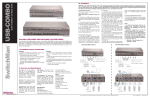
1
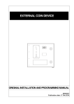
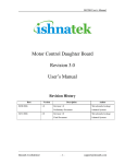
MS3 Manual Dispenser & Automatic Shaker MANUAL ISO 9001: 2000 CERTIFIED CE CERTIFIED Please read this manual carefully before operation. Table of Contents Chapter Page No. 0.0 Table of Contents 1 1.0 Preface 2 2.0 General Safety Instructions 2 3.0 Configuration 4 4.0 Technical Parameters 5 5.0 Installation 5 6.0 Preparations before Operation 6 7.0 Operation 8 8.0 Dispensing 9 9.0 Maintenance 11 10.0 Replacement 13 11.0 Frequent Issues and Troubleshooting 14 12.0 Circuit Diagram 17 14.0 Explosion Diagram 18 15.0 Nameplate 29 -1- 1.0 Preface Thanks for purchasing the Santint Manual Dispenser! This user’s manual provides general information on unpacking, installation, usage and maintenance of the manual dispenser. Any improper use will shorten its longevity. Read this manual completely and carefully before installation, use and maintenance of the machine. The manual should be kept in a convenient place for future reference. For any questions, please do not hesitate to contact our service team. 2.0 General Safety Instructions 1. Warning Labels: Electricity danger! Please unplug before cleaning and repairing. (Remark:No need to switch off the power supply before repairing the canisters assembly.) Important notice! Please read it carefully. 2. The machine must be placed in a well-ventilated working site. Otherwise an aerator must be provided. 3. The applicable power cord: refer to the nameplate in the rear. Make sure the power cord is well grounded to ensure safety. 4. Do not lengthen the power cord as to avoid malfunction or injury. 5. Unplug the MS3 if it is not in use for extended periods of time. 6. When the MS3 needs to be transported to a new site, please secure it by re-inserting the steel rod through the base and re-install the four feet clamps. The turntable must be locked by the locking pole so that it is secure. The canisters should be dismantled, cleaned out and then packed into the cartons. 7. The shaker is compatible with paint cans ranging from 1 liter to 18 liters with a max weight of 35kg. 8. Do not operate or store in a flammable and explosive environment. 9. The sound level is Decibels:≤75dB(A) measured from 1.6m away from the front, back, left, right and above of the machine (see Figure 2.1). -2- Explanation: ——Decibel Meter Locations Testing Data Front 70-75dB(A) Back 70-75dB(A) Left 70-74dB(A) Right 70-74dB(A) Above 68-74dB(A) (Figure 2.1) 10. Surrounding temperature:5℃-50℃; Relative humidity: 15%-90%; 11. Max altitude ≤1000 m. 12. Prior to any maintenance, please unplug the MS3. 13. Use a forklift to gently move the MS3 to the desired location. (see Figure 2.2) (Figure 2.2) -3- 3.0 Configuration Please See Figure 3.1 as below: (Figure 3.1) -4- 4.0 Technical Parameters 1.Model:MS3 2.Shape Size:762X800X1443mm 3.Weight:270±5 kg 4.Power Supply:On Name Plate A.Parameter of Manual Dispenser B.Parameter of Automatic Shaker Dispensing Speed:20rpm Canister's Volume:2.3L Min Dispensing Quantity:1/384Y (0.077ml) Max Dispensing Quantity:2Y (59.14ml) No. of Canisters:12/16/18/20/24/26Canisters Gauge:Optional Shaking Time:60/180/300 Seconds(Optional) Shaking Frequency:680-720rpm Load Capacity Available:1-20L Load Weights Available:1-35kgs Load Can Height Available:50-390mm 5.0 Installation The shaker and turntable assembly are fully assembled before leaving factory. Please assemble the canisters as follows: 1. Unpack the crate carefully. (Figure 5.1) 2. Remove the tools from the crate’s base. 3. Remove the steel rod at the base of the MS3 (see Figure 5.1) and the four feet clamps. Reinstall the steel rods whenever transporting the MS3. 4. To move the MS3, raise the feet by turning them in an anti-clockwise (see Figure 5.2) . 5. Once the MS3 is moved to its final location (must be a flat hard surface), turn the feet in the clockwise direction until all 4 feet are touching the ground and the MS3 is secure and stable.. 6. Rotate the turntable and install the left canisters one by one (see Figure 5.3 and 5.4) Once all canisters are installed, the installation is finished. -5- (Figure 5.2) (Figure 5.3) (Figure 5.4) (Figure 6.1) 6.0 (Figure 6.2) Preparations before Operation In order to ensure that the shaker works well, please refer to the following preparations below: 1. Identification on Control Panel (see Figure 6.1 and 6.2) Figure: “Shaking” mode engaged when T1, T2, or T3 is pressed. -6- Figure: "Shaking" T1 Button—T1 Seconds Button: once pressed, the clamping plate will automatically clamp the paint can and shake the paint can for T1 seconds; T2 Button—T2 Seconds Button: once pressed, the clamping plate will automatically clamp the paint can and shake the paint can for T2 seconds; T3 Button—T3 Seconds Button: once pressed, the clamping plate will automatically clamp the paint can and shake the paint can for T3 seconds. Default time of T1, T2, and T3 is 60s, 180s, and 300s respectively. The times can be adjusted to end users values . Note: Press any two of T1, T2 and T3 to get the sum of their shaking times. Button — Stop and Up Button a) To stop the shaker while in operation, the shaker will stop shaking and clamping plate will be released. b) To stop the clamping plate from raising or lowering. Keep pressed and the clamping plate will continue rising until the button is released. Button — Emergency Stop Button a) Once any emergency occurs, press to immediately stop shaking. b) Release to reinitialize shaker. Button — Mixing Button 1. Paint can must be sealed well, not deformed, and the handle be well secured. 2. Ensure that the Mains switch is in “OFF” position before plugging in an outlet (See Figure 6.3). 3. Ensure that Emergency Stop Button is released. Preparation before operation 1) The colorant in each canister must be fully mixed (It is not recommended to be mixed by shaker as too many bubbles may appear that would cause the chromatic aberration). 2) Remove each canister lid and pour the colorant into the corresponding canister. Attention: Please stick the specified label on each canister to show different colorants! -7- 3) Before operation, remove the air out of each pump. Follow the procedures:: ● Press and hold the Rough release button and pull the Rough gauge upwards to a certain height, ie. 1Y. ● Release the Rough release button back to its original position ● Lift up the plunger handle slowly to its full extent and then press it down gently. Do not move the valve handle during this process. ● Repeat the same procedures 5-6 times; ● Follow the same procedures for the Fine gauge. (Figure 6.4) 7.0 (Figure 6.5) (Figure 7.1) Operation 1) Colorant Mixing Connect power cord to a wall socket and press the button to initiate mixing. To stop mixing, repress the button. Stir 3 times every day, at 10 minutes time intervals (If client has special requirements, the daily stir frequency and time can be altered accordingly). 2) Rotating and Locking of Turntable (See Figure 7.1) Press the brake handle down to the horizontal slot. To lock the turntable: o Rotate the turntable to the desired position. o Release the turntable brake handle back up to the vertical slot. -8- o Move the turntable to the left and right slightly to let the brake handle return to its original position. o The turntable is now locked. 2. Shaking Switch the mains switch to the “ON” position. The shaker will automatically initialize and the LCD will display “Initializing”. After initializing is finished, the LCD will display “Ready”. Open the shaker door and place the paint can on the center of the loading platform on a standard can cushion and close the door (see Figure 7.2). Select the desired time by pressing the button(s). The clamping plate will automatically clamp down on the paint can as the LCD will display “Clamping”. Once the clamping is finished, the shaker will start shaking and the LCD will display “Shaking” and the time countdown. The shaker will stop once the countdown reaches 0 and the LCD will display “Wait, Please”. The clamping plate will automatically release the paint can. Open the door and remove the paint can. When the LCD displays “Ready”, it is ready for the next shaking. Please clean off any paint spills on the clamping plate, loading plate and the two guide screw shafts every day. Warning: A. The shaking without any load or overload is prohibited. B. During shaking, press Emergency Stop down immediately in case of any abnormal noises. C. Press Emergency Stop down immediately in case the shaker has trouble or is locked up during the initializing (Figure 7.2) or clamping. Reinitialize the shaker. D. Unplug before cleaning the shaker. 8.0 Dispensing The minimum shot of the dispenser is one division on the Fine gauge’s dispensing unit is marked at the bottom. For example, 2957/384 means the unit is 1/384 US Fl. Oz. Numbers on the Rough gauge and the Fine gauge have same unit marked at the bottom of the Rough gauge. For example, if the Rough gauge is marked 2957/48, the number “30” on the Rough gauge represents the dispensing value of “30x29.57/48ml.”, and number “2” on the Fine gauge represents the dispensing value of “2x29.57/48ml.” -9- Dispensing Procedures: 01 Determine the dispensing quantity of different colorant as per the formula. 02 Put an open base paint can on the shelf, pull the turntable brake handle down into the horizontal slot, and rotate the turntable until the nozzle is right above the base paint can. Push the turntable brake handle up to the vertical slot and move the turntable left and right slightly to lock the turntable (See Figure 8.1). Attention! Please put the base paint can as close as (Figure 8.1) possible to the spout. 03 Press and hold the Rough (or Fine) button as required, lift up the Rough (or Fine) gauge to required number, and then release the button to lock the gauge (See Figure 8.2). 04 Lift up the plunger handle up to the maximum travel and hold for several seconds to ensure the pump is filled with colorant. Attention! Do not open or operate the valve handle when lifting up plunger handle, otherwise air will enter into the pump and cause inaccurate dispensing (Figure 8.2) 05 Turn the valve handle to an angle of 90º, pull the plunger handle down to its full travel, then release the valve handle slowly back to its original position. Repeat the above procedures for more shots of the same colorant (See Figure 8.3). 06 Press down Rough release button, push the Rough gauge back to zero-scale and then release the Rough release button. 07 Press down Fine release button, push the Fine gauge back to zero-scale and then release the Fine release button. Attention! (Figure 8.3) ● As a precise device, either black or red gauge is vulnerable to damage - 10 - when falling freely to the zero-scale. ● Set the Rough or Fine gauge to zero-scale when it is not in use. ● The aggregation of the shots by black and red gauges should be equal to the dispensing quantity specified in the formula. 08 Use the same method to dispense all the other required colorant into the base paint can. 9.0 Maintenance In order to keep the shaker in good condition, and to extend its life, daily maintenance is recommended. 1. Only qualified personnel can disassemble the shaker. 2. Lubricate the guide screw shafts and shock absorber shaft once every three months with oil (see Figure 9.1). Dispenser Maintenance (Figure 9.1) 1)Daily Maintenance 01 Move each plunger handle up and down three times every day to ensure smooth flow of the colorant and to avoid blockages in pumps and canisters. 02 Clean the nozzle with soft cloth or cotton moistened with water or thinner to keep it unobstructed. 03 Move the valve handle 5 times every day. This can keep the valve in optimum working condition and prevent the colorant from drying in the valve. 04 Check the colorant level in canisters and refill if necessary. If the colorant is lower than the feeding level, air will enter the pump when lifting up the plunger handle. This will cause inaccuracy in dispensing. 2)Weekly Maintenance 01 Check if the canister is loose. If so, tighten the tapping screws under the turntable (see 7.5- Replacement of Canister) 02 Check if the gauge’s scales are damaged or covered with colorant. Clean or replace the gauges if necessary. - 11 - 03 Set the black gauge at its full scale; lift up the plunger handle to check if the shaft is stuck by colorant. If yes, the big piston must be replaced because it has been worn out and/or broken. 3)Periodical Maintenance The dispenser must be maintained every 3-6 months: 01 Check to see if the fixed base is loose or not (Figure 9.2A). If loose, push the base to the bottom most position; fasten two screws of the base symmetrically with inner hexagon Spanner. (Figure 9.2B and 9.2C) Note: don’t screw too hard. 02 Open canister lid during the process of mixing to observe if the agitator works normally. For any abnormity, stop mixing and repair the canister. 03 Cleaning the nozzle: Rotate the valve handle and pull out the nozzle. Clean the nozzle with cotton moistened with water or thinner. Then rotate the valve handle once again to reinstall the nozzle. Attention! After reinstallation of nozzle, dispense out certain amount of colorant to fill the nozzle. The reinstallation must be carried out carefully. The M3 by default is installed with a large-size nozzle. The end user can choose to install a different size nozzle according to the colorant’s viscosity. A B C (Figure 9.2) 4)Yearly Maintenance After a long period of use, colorant may be stuck to the inner wall of the pump and canister. This will make the piston difficult to move and cause measurement errors. If this is the case, cleaning must be done to canisters and pumps. 01. Remove the canister assembly from the turntable. 02. Pour any remaining colorant from the canister into a clean container. 03. Clean the canister with warm water to get rid of most of the adhesive colorant. - 12 - 04. Properly dispose the mix of cleaner and colorant according to local environmental regulations. 05. Reinstall the canister on the turntable. 06. Add some cleaner into the canister. 07. Set the Rough gauge to its maximum scale. 08. Put a container right below the nozzle and then operate as dispensing procedures (6.3). 09. Set the Fine gauge to its maximum scale. 10. Place a container right below the nozzle and then operate as dispensing procedures (6.3). 11. Repeat steps 7-9 until the canister is clean (the cleaner can be used for 1-3 times. Yet fresh cleaner is required for the final cleaning). 12. Leave the canister to dry before re-filling with fresh colorant. 10.0 Replacement Replace Sniff-Back Piston 01. Rotate the valve handle and pull out the nozzle. 02. Rotate the valve handle to its maximum travel and hold. 03. Pull out the sniff-back piston. 04. Install a new sniff-back piston with small O-ring. 05. Reinstall the nozzle. 06. Release the valve handle. Replace Canister 01. Loosen but do not remove the three screws that fix the canister under the turntable using the inner hexagon wrench. Rotate the canister clockwise to remove from the turntable. 02. While installing the new canister, place the three M6 screws at the bottom of the canister into the larger ends of the three cone-shaped holes in the turntable. Caution: Must insert the canister crank into the plastic sleeve in the turntable (see Figure 7.5.1). 03. Rotate the canister anti-clockwise, shift the canister’s three screws to the smaller ends of the cone-shaped holes, and then fix the screws with inner hexagon wrench from the bottom of the turntable (See figure 6.1). - 13 - 11.0 Frequent Issues and Troubleshooting For issues not listed, please contact us. Troubles Diagnoses Motor doesn’t work Power supply Troubleshooting does not Check if the Mains Switch is with charge, engage. the plug is plugged well. The fuse is broken. Replace fuse. The wire to the motor is not Open the top cover plate, reconnect the connected. wire. The motor is broken Replace motor. The belt is loose. Fasten the belt. Uneven flow of colorant Air bubbles in the cylinder See "Preparation Before Operation ". Allow from Colorant in canister is low. the bubbles to escape Dried deposits of colorant Top off colorant. causing blocks. Clean canister assembly and the nozzle during dispensing. relevant parts. Canister is loose on turntable. Colorant doesn’t dispense easily. Piston doesn’t move easily. Loose fastening screws. Tighten fastening screws. Nozzle blocked. Clean nozzle. Colorant has dried and hardened in the canister. Canister and pump should be removed, emptied and cleaned thoroughly. Replenish with new colorant. The crank shaft under the Agitator doesn’t move during mixing. canister is not attached to the plastic sleeve of the Reinstall the canister. rotating panel. Colorant leakage at the nozzle. Worn out O-ring. Replace O-ring. - 14 - Check if the Mains Switch is with charge, Power supply is not working. the plug is plugged well and the mains switch is “ON” position. LCD has no display The fuse or the power supply Replace the fuse or power cord. cord is broken. The DC motor wire is broken. Replace DC motor wire. LCD displays “Clamping Circuit Board is System Trouble” Replace the Circuit Board. malfunctioning. DC motor runs for several The connection of magnetic seconds, switch is broken. Replace it. then running stops suddenly, The magnetic switch is “Clamping System Trouble” Replace it. damaged. displays on LCD. Large cans cannot be shaken. The belt is loose. Tighten it moderately. 1. “Emergency Stop” is not Release it LCD displays “Emergency released. Stop Pressed” 2. “Emergency Stop” is damaged or its connection is broken. LCD displays “Door Open” Replace “Emergency Stop” or re-connect the connection Door is not closed. Close the door. The wire capacity of the AC Replace the larger gauge wire or equip with motor is not enough. a voltage-stabilizer Once AC motor starts up, LCD will display “Initializing” 1.The capacitor of AC motor Does not shake Replace the capacitor of AC motor. after is broken clamping. 2. AC motor is broken. - 15 - Replace AC motor. During shaker’s shaking, the noise and The shaker is not leveled. Adjust the feet to level. The paint can is deformed. Replace with a normal paint can. Overloaded Decrease load. vibrations increase. After the clamped, paint the can LCD is still displays “shaking” and the second counter is counting Flip the switch in the capacitor box mounted Start-up capacitor is broken. down normally; AC motor in the front end of AC motor to the other position. utters abnormal noises and doesn’t shake. 1. Disconnect power supply to let the motor cool down. Restart the shaker in 1 (one) AC Motor overload with too The Motor is overheated much or too little voltage for an extended period of time. hour. 2.Equip with a voltage stabilizer and decrease the load 3. If the heat-protection switch is frequently activated, check the electrical circuit. - 16 - 12.0 Circuit Diagram Insert the electric circuit diagram - 17 - 13.0 Explosion Diagram Explosion Diagram of Shell: No. Name 1 Triangle Belt 2 Motor Wheel No. 3 4 Name Motor for Mixing Circuit Board for Display - 18 - Explosion Diagram of Inner Frame Assembly No. 1 2 3 Name DC Motor for Clamping Clamping Plate Bearing Base for Loading Plate No. 4 5 - 19 - Name Synchronized Belt Principal Axis Assembly Explosion Diagram of Middle Frame Assembly No. 1 2 Name V Triangle Belt DC Motor - 20 - Explosion Diagram of Base Frame Assembly No. 1. Name Shock Absorption Assembly - 21 - Explosion Diagram of Shock Absorption Assembly No. 1 Name Washer - 22 - Explosion Diagram of Principal Axis Assembly No. 1 Name UCP206 Bearing - 23 - No. 1 Name Main Circuit Board - 24 - Explosion Diagram of Assembly of Piston Kit No. Name No. Name 1 2 3 4 5 6 7 8 Screw (M4x10) Plunger Handle Screw (M4x10) Red Gauge (Fine Gauge) Small Piston Shaft Small Piston Small Piston Head Large Piston Head 9 10 11 12 13 14 15 16 Large Piston Large Piston Wiper Circlip for Shaft Small Piston Shaft Fixed Base Assembly Set Screw (M4x6) Active Base Assembly Black Gauge(Coarse Gauge) - 25 - Explosion Diagram of Assembly of Canister No. Name No. 1 Canister Lid 5 2 Collar Pin 6 3 Agitator 7 4 Shaft Bushing of Agitator - 26 - Name Canister Crankshaft Tapping Screw Explosion Diagram of Assembly of Canister/Pump No. Name No. Name 1 Bolt(M4X10) 11 Sniff-Back Piston 2 Piston Kit Gauge 12 Rubber Cover, Wiper 3 Pump Assembly 13 Wiper 4 Valve Assembly 14 Pan-Head Screw(M3X16) 5 O-ring(8X1.8) 15 Vale Handle 6 Nozzle 16 Torsion Spring 7 O-ring(7.2X1.8) 17 O-ring(16X1.8) 8 Washer 18 Fixing Nut, Linking Block 9 Vale Pole 19 Canister Kit 10 O-ring(3.15X1.8) - 27 - Explosion Diagram of Assembly of Turntable No. 1 2 3 4 5 6 7 8 Name Protection Cap Stelliform Plate Plastic Sleeve Plastic Washer Eccentric Shaft Base Big Nut Stop Washer Big Plastic Washer No. 9 10 11 12 13 14 15 16 Name Rotary Shaft Principle Axis Wheel Bearing Base Support Stopper Bearing Turntable Shore - 28 - 14.0 Nameplate Name plate - 29 - ZHENGZHOU SANHUA TECHNOLOGY & INDUSTRY CO., LTD. Address: Xushui Industrial & Trading Park, Zhongyuan West Road, Zhengzhou, Henan Province, P. R. China Postcode: 450042 Tel:0371—65110760,800-8836987 / Fax:0371-67857219 website: www.santint.com e-mail: [email protected]