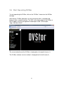
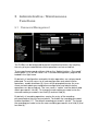
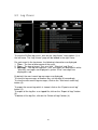
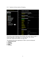
1
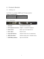
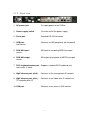
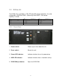
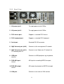
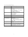
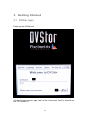
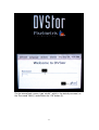
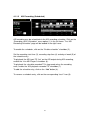
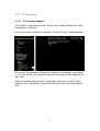
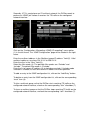
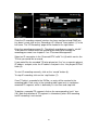
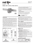
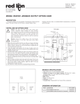
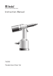
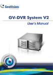
DVStor Transport Storage System User Manual (V5.0) 1 Pixelmetrix reserves the right to make changes in the specifications and other information contained in this publication without prior notice. Pixelmetrix shall not be liable for errors contained herein or incidental damages in connection with the furnishing, performance, or use of the material. For more information, please contact Pixelmetrix at: Pixelmetrix Corporation 31 Kaki Bukit Road 3 #07-03 Techlink Singapore 417818 Website: http://www.pixelmetrix.com Copyright 2009 Pixelmetrix Corporation. All rights reserved. Trademarks All registered trademarks are property of their respective owners. Pixelmetrix is not responsible for the performance of these products. Register your DVStor at http://www.pixelmetrix.com to get the ID and password to access our secured customer section and FTP site, and be updated about events and news of Pixelmetrix. You’ll also receive the Software Registration Code when you register. PPN: Revision: 5.0 2 Contents 1 About this manual...........................................................................................................5 2 Product Models ...............................................................................................................6 2.1 DVStor-1U..................................................................................................................6 2.1.1 Front view .............................................................................................................6 2.1.2 Back view..............................................................................................................7 2.1.3 Technical Specifications .......................................................................................8 2.2 DVStor-4U..................................................................................................................9 2.2.1 Front View ............................................................................................................9 2.2.2 Back View...........................................................................................................10 2.2.3 Technical Specifications .....................................................................................11 2.3 DVStor2-3U...............................................................................................................12 2.3.1 Front View (With Front Bezel)...........................................................................12 2.3.2 Front View (Without Front Bezel)......................................................................13 2.3.3 Back View...........................................................................................................14 2.3.4 Technical Specifications .....................................................................................15 3 Getting Started ..............................................................................................................16 3.1 DVStor login.............................................................................................................16 3.2 DVStor desktop screen lock......................................................................................19 3.3 DVStor logout/shutdown ..........................................................................................20 3.4 Initial Software Setup ...............................................................................................22 3.4.1 Date/Time Setup .................................................................................................22 3.4.2 IP Address Setup.................................................................................................25 3.5 Start Operating DVStor.............................................................................................28 4 Operational Functions ..................................................................................................29 4.1 TS Recording ............................................................................................................29 4.1.1 ASI Recording ....................................................................................................30 4.1.1.1 ASI Recording (Manual)................................................................................30 4.1.1.2 ASI Recording (Scheduled) ...........................................................................33 4.1.2 IP Recording .......................................................................................................34 4.1.2.1 IP Recording (Manual)...................................................................................34 4.1.2.2 IP Recording (Scheduled) ..............................................................................38 4.1.3 Recording Options ..............................................................................................39 4.1.3.1 TS File Size....................................................................................................39 4.1.3.2 In-Place Transrating.......................................................................................40 4.1.3.3 PID Filtering ..................................................................................................42 4.2 TS Playback ..............................................................................................................43 4.2.1 ASI Playback ......................................................................................................43 4.2.1.1 ASI Playback (Time) .....................................................................................43 4.2.1.2 ASI Playback (Filename) ...............................................................................45 4.2.1.3 ASI Playback Options....................................................................................46 4.2.2 IP Playback .........................................................................................................47 4.2.2.1 IP Playback (Time) ........................................................................................47 4.2.2.2 IP Playback (Filename)..................................................................................50 3 4.2.2.3 IP Playback (Delayed) ...................................................................................53 4.2.2.4 IP Playback Options.......................................................................................55 4.2.3 Video Thumbnail Playback.................................................................................56 4.2.3.1 Video Thumbnail Summary List....................................................................57 4.2.3.2 Video Thumbnail Sequence Generation (Time) ............................................58 4.2.3.3 Video Thumbnail Sequence Display (Time) .................................................60 4.2.3.4 Video Playback (IP) .......................................................................................62 4.2.3.5 TS Playback (ASI) .........................................................................................64 4.2.3.6 Video Thumbnail Sequence Generation (Live) .............................................65 4.2.3.7 Video Thumbnail Sequence Display (Live)...................................................66 4.3 TS Export / Backup / Upload....................................................................................67 4.3.1 TS File Export.....................................................................................................67 4.3.2 TS Segment Export .............................................................................................68 4.3.3 TS File Upload....................................................................................................70 4.3.4 External USB Drive Backup ...............................................................................71 4.3.4.1 USB Drive Formatting ...................................................................................71 4.3.4.2 USB Drive TS Backup (Manual) ...................................................................72 4.3.4.3 USB Drive TS Backup (Scheduled)...............................................................73 4.3.4.4 USB Drive TS File Export .............................................................................74 4.3.4.5 USB Drive Unmounting.................................................................................75 4.4 System Configuration ...............................................................................................76 4.4.1 General Configuration ........................................................................................76 4.4.2 SNMP Target Configuration...............................................................................77 5 5.1 5.2 5.3 5.4 5.5 6 Administrative / Maintenance Functions....................................................................78 Password Management .............................................................................................78 Log Viewer ...............................................................................................................80 System Information Display .....................................................................................81 Software Upgrade .....................................................................................................82 TS Storage Calculator ...............................................................................................83 Appendix........................................................................................................................84 6.1 SNMP MIBs..............................................................................................................84 6.2 VLC Media Player Installation .................................................................................85 6.3 FileZilla Server Installation ......................................................................................86 4 1 About this manual The DVStor transport stream storage system provides real-time recording and playback of MPEG transport streams via an IP or ASI interface. It may be used for compliance recording or content audit purposes. The DVStor software runs on the Linux Fedora Core 4 operating system for maximum stability and reliability. This manual gives you step-by-step instructions for using the various functions in the DVStor. 5 2 Product Models 2.1 DVStor-1U The DVStor-1U is available in 500GB and 1TB storage capacities. Storage availability table Physical storage TS storage (RAID-0) 500GB 450GB 1TB 900GB 2.1.1 Front view 1. Serial port : Standard RS-232 connector. 2. PS/2 keyboard connection : Supports a standard PS/2 keyboard. 3. Power switch : Powers up or shuts down the unit. 4. Reset switch : Resets the unit. 5. Power LED indicator : Indicates whether the unit is powered up. 6. HDD LED indicator : Indicates whether there is hard disk activity. 7. DVD-ROM eject button : Ejects the DVD-ROM. 6 2.1.2 Back view 1. AC power jack : To supply power to the DVStor. 2. Power supply switch : To switch on/off the power supply. 3. Serial port : Standard RS-232 connector. 4. USB port : and mouse) Connects to USB peripheral (eg. keyboard 5. DVB-ASI input : stream. ASI input for recording MPEG transport 6. DVB-ASI output : stream. ASI output for playback of MPEG transport 7. PS/2 keyboard/mouse port : Supports standard PS/2 keyboard and mouse with Y-cable. 8. GigE ethernet port (eth0) : Connects to the management IP network. 9. GigE ethernet port (eth1) : TS recording over IP. Connects to an Video-over-IP network for 10. VGA port : Connects to an external VGA monitor. 7 2.1.3 Technical Specifications CPU Intel Core2 Duo 2.4GHz Memory 1GB Auxiliary Interfaces 2 x Serial ports, 1 x USB port 1 x PS/2 keyboard/mouse port 2 x Gigabit ethernet ports 1 x VGA port, 1 x DVD-ROM drive Storage 500GB or 1TB SATA2 RAID-0 DVB-ASI interface 2 x 75Ω BNC connectors Maximum recording rate 80Mbps Maximum playback rate 80Mbps Chassis specification 1U rack-mount Heavy duty steel chassis Dim : 44mm (H) x 440mm (W) x 482.6mm (D) Weight : ~9kg Power supply 250W Electrical 100-240 Vac, 50-60Hz 80A max In-rush current Temperature Operating temperature : +10°C to 40°C Storage temperature : 0°C to 50°C Regulatory CE Mark 8 2.2 DVStor-4U The DVStor-4U is available in 1TB, 2TB and 4TB storage capacities. It can be configured as RAID-0 or RAID-1 (Mirroring). With RAID-1, the storage capacity is halved. Physical storage 1TB 2TB 4TB TS storage (RAID-0) 900GB 1.8TB 3.6TB TS storage (RAID-1) 450GB 900GB 1.8TB 2.2.1 Front View 1. Power switch : Powers up or shuts down the unit. 2. Reset switch : Resets the unit. 3. Power LED indicator : Indicates whether the unit is powered up. 4. HDD LED indicator : Indicates whether there is hard disk activity. 5. DVD-ROM eject button : Ejects the DVD-ROM. 9 2.2.2 Back View 1. Power supply switch 1 : To switch on/off power supply 1. 2. Power supply switch 2 : To switch on/off power supply 2. 3. AC power jack : To supply power to the DVStor. 4. PS/2 mouse port : Supports a standard PS/2 mouse. 5. PS/2 keyboard port : Supports a standard PS/2 keyboard. 6. Serial port : Standard RS-232 connector. 7. GigE ethernet port (eth0) : Connects to the management IP network. 8. GigE ethernet port (eth1) : TS recording over IP. Connects to an Video-over-IP network for 9. USB port : mouse). Connects to USB peripheral (eg. keyboard, 10. DVB-ASI input : stream. ASI input for recording MPEG transport 10 11. DVB-ASI output : stream. ASI output for playback of MPEG transport 12. VGA port : Connects to an external VGA monitor. 2.2.3 Technical Specifications CPU Intel Core2 Duo 2.4GHz Memory 1GB Auxiliary Interfaces 1 x Serial port, 1 x Parallel port 4 x USB ports 1 x PS/2 keyboard port, 1 x PS/2 mouse port 2 x Gigabit ethernet ports 1 x VGA port, 1 x DVD-ROM drive Storage 1TB, 2TB or 4TB SATA2 RAID-0 or RAID-1 DVB-ASI interface 2 x 75Ω BNC connectors Maximum recording rate 80Mbps Maximum playback rate 80Mbps Chassis specification 4U rack-mount Standard : EIA 19-inch (Electronic Industries Association) Heavy duty steel chassis Dim : 178mm (H) x 490mm (W) x 531mm (D) Weight : ~23kg Power supply Dual ATX 300W redundant Electrical 90-240Vac, 47-63Hz 5.0A at 115Vac, 2.5A at 230Vac Temperature Operating temperature : +10°C to 40°C Storage temperature : 0°C to 50°C Regulatory CE Mark, UL Listed 11 2.3 DVStor2-3U The DVStor2-3U is available in 8TB and 16TB storage capacities. It has 16 hot-swappable hard disk drive bays. The supported RAID configurations are RAID-6 (default) and RAID-5. Storage availability table Physical storage TS storage (RAID-6) 8TB 5.32TB 16TB 12.68 TB TS storage (RAID-5) 6.24 TB 13.6 TB The storage capacity can be extended with a direct attached storage system (DAS) which is connected via the SCSI interface. 2.3.1 Front View (With Front Bezel) 1. Power LED indicator : Indicates whether the unit is powered up. 2. HDD LED indicator : Indicates whether there is hard disk activity. 12 2.3.2 Front View (Without Front Bezel) 1. DVD-ROM eject button : Ejects the DVD-ROM. 2. Hard disk bay : Hot-swappable hard disk bay. 3. USB port : and mouse). Connects to USB peripheral (eg. keyboard 4. Serial port : Standard RS-232 connector. 5. Reset button : Resets the unit. 6. Power button : Powers up or shuts down the unit. 13 2.3.3 Back View 1. AC power jack 1 : To supply power to the DVStor. 2. AC power jack 2 : To supply power to the DVStor. 3. PS/2 mouse port : Supports a standard PS/2 mouse. 4. PS/2 keyboard port : Supports a standard PS/2 keyboard. 5. Serial port : Standard RS-232 connector. 6. GigE ethernet port (eth0) : Connects to the management IP network. 7. GigE ethernet port (eth1) : TS recording over IP. Connects to an Video-over-IP network for 8. USB port : mouse). Connects to USB peripheral (eg. keyboard, 9. DVB-ASI input : stream. ASI input for recording MPEG transport 10. DVB-ASI output : stream. ASI output for playback of MPEG transport 11. VGA port : Connects to an external VGA monitor. 14 2.3.4 Technical Specifications CPU Intel Core2 Duo 2.4GHz Memory 1GB Auxiliary Interfaces 2 x Serial ports, 1 x Parallel port 6 x USB ports 1 x PS/2 keyboard port, 1 x PS/2 mouse port 2 x Gigabit ethernet ports 1 x VGA port, 1 x DVD-ROM drive Storage 16 x 3.5” SATA hot-swap drive bays 8TB or 16TB SATA2 RAID-5 or RAID-6 DVB-ASI interface 2 x 75Ω BNC connectors Maximum recording rate 80Mbps Maximum playback rate 80Mbps Chassis specification 3U rack-mount Heavy duty aluminum chassis Dim : 132mm (H) x 437mm (W) x 648mm (D) Weight : ~35kg Power supply 800W (1 + 1) redundant AC-DC high-efficiency with PFC Electrical 100-240Vac, 50-60Hz, 10-4A Temperature Operating temperature : +10°C to 35°C Storage temperature : -40°C to 70°C Regulatory CE Mark, UL Listed 15 3 Getting Started 3.1 DVStor login Power up the DVStor unit. On the first login screen, type “root” on the “Username” field (1) and click on the “OK” button (2). 16 On the second login screen, type “dvst0r”, which is the default password, on the “Password” field (1) and click on the “OK” button (2). 17 Once you have login successfully, you will see the desktop as shown above. 18 3.2 DVStor desktop screen lock To lock the DVStor desktop screen against any unauthorized access, click on the “lock” button on the bottom right hand corner of the desktop. If there is no keyboard or mouse activity for five minutes, the desktop will also be automatically locked against any unauthorized access. To unlock the desktop screen, type in the root password in the “Password” field and click on the “Unlock” button. The default root password is “dvst0r”. 19 3.3 DVStor logout/shutdown To logout from the DVStor, click on the “logout” button on the bottom right hand corner of the desktop. Click on the “End Current Session” button of the “End Session for root” window. 20 To shutdown the DVStor, click on the “Actions” menu option, followed by the “Shut Down” menu sub-option. 21 3.4 Initial Software Setup 3.4.1 Date/Time Setup To setup the date and time, click on the “Setup Date and Time” shortcut on the DVStor desktop. Select the “Date & Time” tab on the “Date/Time Properties” window. Change the date and time accordingly. 22 To enable NTP (Network Time Protocol), click on the “Network Time Protocol” tab. Check the “Enable Network Time Protocol” checkbox. Select the appropriate NTP server. 23 To select the time zone, click on the “Time Zone” tab. Click on the desired time zone on the map or select the desired time zone from the list box. The “System clock uses UTC” checkbox should be unchecked. Click on the “OK” button to save the date and time settings. 24 3.4.2 IP Address Setup To setup the DVStor IP address, click on the “Setup IP address” shortcut on the DVStor desktop. On the “Network Configuration” window, select the “eth0” device in the list box and click on the “Edit” button to modify its IP settings. The “eth0” port should be connected to the management network. 25 On the “Ethernet Device” window for “eth0”, enter the desired IP address, subnet mask, default gateway address, and click on the “OK” button. The default IP address for “eth0” is 192.168.15.182. The default subnet mask for “eth0” is 255.255.255.0. On the “Network Configuration” window, select the “eth1” device in the list box and click on the “Edit” button to modify its IP settings. The “eth1” port should be connected to the Video-over-IP network for TS recording over IP. 26 On the “Ethernet Device” window for “eth1”, enter the desired IP address, subnet mask, default gateway address, and click on the “OK” button. The “eth1” IP address should be in a separate subnet from that of “eth0”. The default IP address for “eth1” is 192.168.16.182. The default subnet mask for “eth0” is 255.255.255.0. To save the IP settings, click on the “x” button at the top right hand corner of the “Network Configuration” window. Click “Yes” to the question “Do you want to save your changes?”. 27 3.5 Start Operating DVStor To start operating the DVStor, click on the “DVStor” shortcut on the DVStor desktop. Alternatively, DVStor operations can be carried out with a standard web browser from a remote machine. The URL to the home page of the DVStor is the IP address for the management network port “eth0”, for example, “http://192.168.15.182”. The current date/time of the DVStor is displayed on the top left frame (1). The DVStor software version number is displayed on the left frame (2). 28 4 Operational Functions 4.1 TS Recording The DVStor is able to record transport stream via the IP or ASI interface. Only one interface may be selected for TS recording at any given time. Recording from both IP and ASI interface simultaneously is not allowed. Transport stream recording may be initiated manually or through a scheduler. Recorded TS files are managed in a FIFO (First In, First Out) manner. When the hard disk is more than 99% full, the oldest recorded TS file will be deleted automatically to make way for the newly recorded TS file. A recorded TS segment, which is defined by a start time and stop time, may be locked to prevent it from being deleted. The default maximum size of each recorded TS file is 2GB and its duration is always an exact multiple of one minute. The maximum size of each recorded TS file may be specified by the user (See chapter 4.1.3.1). 29 4.1.1 ASI Recording 4.1.1.1 ASI Recording (Manual) To record from the ASI interface manually, click on the “Recording->ASI>Manual (Time)” menu option (1) in the left frame. The “ASI Recording (Time)” page will be loaded in the right frame. To playback the ASI input TS “live” on the ASI output during ASI recording, enable the “Live ASI playout” checkbox (5). To start ASI recording, enter the recording password (4) and click on the “record” button (3). The default recording password is “dvst0r”. To disable the need to enter the recording password or to change the recording password, see chapter 5.1 on “Password Management”. To stop ASI recording, click on the “stop” button (2). Once TS data is recorded in the DVStor, an entry will be created in the recording table. Each entry in the recording table represents a contiguous recorded TS segment, which is defined by its start time and stop time. To delete a recorded TS segment, click on the corresponding “trash” icon (7). Note that deletion of TS segment is allowed only when ASI recording and IP recording is not started. 30 To prevent a recorded TS segment from being deleted, click on the corresponding status icon (6) which is in the unlocked state. The “Lock TS Segment” page will be loaded in the right frame. Specify the start time and stop time of TS segment to lock and click on the “Lock TS Segment” button. A new entry will be created for the locked TS segment in the recording table whereby the status icon is in the locked state (1). 31 Alternatively, transport stream may be manually recorded via the ASI interface to a file named by the user. Click on the “Record->ASI->Manual (File)” menu option (1) in the left frame. The “ASI Recording (File)” page will be loaded in the right frame. Enter the recording password in field (2). Enter the TS file name in field (5). Enter the size of the TS file to record in field (6). To start recording, click on the record button (4). To stop recording, click on the stop button (3). To rename a TS file, click on the corresponding rename hyperlink (7). Enter the new file name in the “Rename TS” window and click on the “OK” button. To download a TS file, click on the corresponding download icon (8). To delete a TS file, click on the corresponding trash icon (9). 32 4.1.1.2 ASI Recording (Scheduled) ASI recording may be scheduled via the ASI recording scheduler. Click on the “Recording->ASI->Scheduler” menu option (1) in the left frame. The “ASI Recording Scheduler” page will be loaded in the right frame. To enable the scheduler, click on the “Enable scheduler” checkbox (2). Set the recording start time (3), recording stop time (4) and day of week (5) of the schedule entry. To playback the ASI input TS “live” on the ASI output during ASI recording, enable the “Live ASI Playout” checkbox (6). To playback the schedule-recorded TS in loop mode when the recording ends, enable the “ASI playback recorded TS” checkbox (7). To add the schedule entry, click on the “Add” button (8). To remove a schedule entry, click on the corresponding “trash” icon (9). 33 4.1.2 IP Recording 4.1.2.1 IP Recording (Manual) The DVStor can be used to record TS over the IP network. Before that, some configuration is required. Firstly, the network interface for recording TS over IP needs to be configured. Click on the “Configuration->Recording->Network (IP recording)” menu option (1) in the left frame. The “Network Interface Config” page will be loaded in the right frame. Select the network interface for IP recording by clicking on the “eth0” radio button or “eth1” radio button. The default network interface for IP recording is “eth1”. 34 Secondly, if TS is carried over an IP multicast network, the DVStor needs to perform an “IGMP join” before it receives the TS traffic on the configured network interface. Click on the “Configuration->Recording->IGMP (IP recording)” menu option (1) in the left frame. The “IGMP Configuration” page will be loaded in the right frame. Enter the multicast address in the “Multicast group IP address” field (2). Valid multicast addresses are from 224.X.X.X to 239.X.X.X. Enter the alias in the “Alias” field (3). Select the filter mode (4). The possible filter modes are “Exclude” and “Include”. The default filter mode is “Exclude”. Enter the list of source IP address (6) to include or exclude. If include mode selected is selected, at least one source IP address must be specified. To add an entry to the IGMP configuration list, click on the “Add Entry” button. To delete an entry from the IGMP configuration list, click on the corresponding “trash” icon (8). To join a multicast group so that the DVStor starts receiving TS traffic on the configured network interface, check on the corresponding “Join” checkbox (7). To leave a multicast group so that the DVStor stops receiving TS traffic on the configured network interface, uncheck the corresponding “Join” checkbox (7). 35 Once the IP recording network interface has been configured and IGMP join has been issued, click on the “Recording->IP->Manual” menu option (1) in the left frame. The “IP Recording” page will be loaded in the right frame. Enter the recording password (2). The default recording password is “dvst0r”. To disable the need to enter the recording password or to change the recording password, see chapter 5.1 on “Password Management”. Select an IP connection in the “Scanned IPTV traffic” list (6) which carries the TS that you would like to record. If you would like the recorded TS to be played out “live” on a separate playout IP address and port, enter the IP address and port in the “Live playout IP/Port” fields (5). To start IP recording manually, click on the “record” button (8). To stop IP recording, click on the “stop” button (7). Once TS data is recorded in the DVStor, an entry will be created in the recording table. Each entry in the recording table represents a contiguous recorded TS segment, which is defined by its start time and stop time. To delete a recorded TS segment, click on the corresponding “trash” icon (10). Note that deletion of TS segment is allowed only when ASI recording and IP recording is not started. 36 To prevent a recorded TS segment from being deleted, click on the corresponding status icon (9) which is in the unlocked state. The “Lock TS Segment” page will be loaded in the right frame. Specify the start time and stop time of TS segment to lock and click on the “Lock TS Segment” button. A new entry will be created for the locked TS segment in the recording table whereby the status icon is in the locked state (1). 37 4.1.2.2 IP Recording (Scheduled) IP recording may be scheduled via the IP recording scheduler. Click on the “Recording->IP->Scheduler” menu option (1) in the left frame. The “IP Recording Scheduler” page will be loaded in the right frame. To enable the scheduler, click on the “Enable scheduler” checkbox (2). Set the day of week, start time and stop time of the schedule entry in the “Recording schedule” fields (3). Select an IP connection in the “Scanned IPTV traffic” list (9) which carries the TS that you would like to record. If you would like the recorded TS to be played out “live” on a separate playout IP address and port, enable the “Live playout” checkbox (5). To playback the schedule-recorded TS in loop mode when IP recording ends, enable the “Playback recording” checkbox (6). Enter the playout IP address and port in the “Playout destination IP/Port” fields (7). To add the schedule entry, click on the “Add” button (8). To remove a schedule entry, click on the corresponding “trash” icon (10). 38 4.1.3 Recording Options 4.1.3.1 TS File Size To configure the maximum size of each recorded TS file, click on the “Configuration->Recording->TS Size” menu option (1) in the left frame. The “TS Size Configuration” page will be loaded in the right frame. Enter the maximum TS file size in text field (2). The default maximum TS file size is 2000MB. To save the settings, click on the “Save Settings” button (3). Since the duration of each recorded TS file is always an exact multiple of one minute, the actual TS file size may vary slightly from the maximum file size specified. 39 4.1.3.2 In-Place Transrating Video in the recorded transport stream may be transrated to a low bitrate for compliance recording purpose, where VHS/VCD quality will suffice. In-place transrating is supported only for non-encrypted services. Audio is preserved in its original quality and all SI/PSI data in the TS is kept intact. Currently, the DVStor supports in-place transrating of the following combination of video in the TS. - 4 MPEG2 SD video - 1 MPEG2 HD video and 1 MPEG2 SD video - 1 H.264 SD video At the moment, in-place transrating of H.264 HD video is not supported. To configure in-place transrating options, click on the “Configuration>Recording->In-Place Transrating” menu option (1) in the left frame. The “InPlace Transrating Configuration” page will be loaded in the right frame. To enable in-place transrating, activate checkbox (2). Transrating must be enabled before date/time burning, program name burning and event name burning in the recorded video is allowed. Select the bitrate of each transrated video in dropdown box (3). The possible values are 500kbps and 250kbps. 40 To “burn” the recording date/time in the transrated video, select the date/time burning option in dropdown box (4). The possible options are “None”, “TopLeft”, “TopRight”, “BottomLeft”, “BottomRight”, “TopTicker” and “BottomTicker”. To “burn” the program name in the transrated video, enable checkbox (5). The program name is extracted from the SDT (Service Descriptor Table) in the TS. To “burn” the event name in the transrated video, enable checkbox (6). The event name is extracted from the EIT (Event Information Table) in the TS. To save the configuration, click on the “Save Configuration” button. 41 4.1.3.3 PID Filtering Certain PIDs in the TS may be excluded for recording by using the “PID Filtering” feature. Click on the “Configuration->Recording->PID Filtering” menu option in the left frame. The “PID Filtering (ASI/IP Recording)” page will be loaded in the right frame. The default mode is “No PID filtering”, whereby the entire TS is recorded. To include certain PIDs for recording, click on the “INCLUDE list” radio button (3). To add a PID to the include list, enter the PID number in text field (6) and click on the “Add PID(s)” button. To add a range of PIDs to the include list, enter the lower bound PID number in text field (8), the upper bound PID number in text field (9), and click on the “Add PID Range” button (7). To delete a PID from the include list, click on the corresponding “trash” icon (11). To delete all the PIDs in the include list, click on the “Delete All PIDs” button (10). To exclude certain PIDs for recording, click on the “EXCLUDE list” radio button (4). A useful feature would be to exclude only the stuffing PID 0x1FFF for recording. During ASI playback, the stuffing packets will be inserted back to the TS in the original places. This feature allows a longer duration of TS to be stored in the DVStor without any loss of information. 42 4.2 TS Playback Recorded transport stream may be played back via the ASI or IP interface. Transport stream files from an external source may be uploaded to the DVStor for playback too. 4.2.1 ASI Playback 4.2.1.1 ASI Playback (Time) To playback a recorded TS segment via the ASI interface, click on the “Playback->ASI->Time” menu option (1) in the left frame. The ASI Playback (Time) page will be loaded in the right frame. Set the start date/time (7) and stop date/time (8) of the TS to playback. Alternatively, the start date/time and stop date/time can be set by clicking on the date/time hyperlink (11) of a particular event in the EPG (Electronic Program Guide), which is based on the EIT (Event Information Table) in the TS. To view the EPG for a particular program and time segment, select the EPG date (9), time segment, and program (10) accordingly. 43 To playback in loop mode, enable the “Loopback mode” checkbox (5). To start playback of TS for the specified start time and stop time, click on the “Play” button (3). Alternatively, to playback a segment of TS based on an event in the EPG, click on the corresponding thumbnail (12). To pause playback, click on the “Pause” button (3). To stop playback, click on the “Stop” button (2). 44 4.2.1.2 ASI Playback (Filename) To playback a TS file via the ASI interface, click on the “Playback->ASI->File” menu option (1) in the left frame. The “ASI Playback (File)” page will be loaded in the right frame. The TS file can either be uploaded from an external source or recorded using the “ASI Recording (File)” function. For instructions on uploading a TS file, refer to chapter 4.3.3 on “TS File Upload”. To select a TS file for playback, click on the corresponding hyperlink (9). To playback in loop mode, enable the “Loopback mode” checkbox (5). To playback at the original bitrate (as calculated from the PCR values in the TS file), click on radio button (6). To playback at user-defined bitrate, click on radio button (7) and enter the bitrate in text field (8). To start playback, click on the playback button (4). To stop playback, click on the stop button (2). To pause playback, click on the pause button (3). To rename a TS file, click on the corresponding rename hyperlink (10). Enter the new file name in the “Rename TS” window and click on the “OK” button. To download a TS file, click on the corresponding download icon (11). To delete a TS file, click on the corresponding trash icon (12). 45 4.2.1.3 ASI Playback Options To configure ASI playback options, click on the “Configuration->Playback>ASI Playback” menu option (1) in the left frame. The “ASI Playback Configuration” page will be loaded in the right frame. To enable ASI playback of recorded TS at a user-defined bitrate, activate checkbox (2) and enter the bitrate in text field (3). To enable error-free playback during TS looping, activate checkbox (4). The continuity count, PCR, PTS and DTS values in the TS are restamped to achieve error-free loopback. To save the configuration, click on the “Save Configuration” button (5). 46 4.2.2 IP Playback Recorded contents in the DVStor can be streamed to a remote PC for viewing via an IP network. Up to three clients may use the IP playback function simultaneously to view the recorded contents. The VLC media player plugin is required for viewing video on the remote PC browser. Refer to Appendix 6.2 “VLC media player installation” for instructions on downloading and installing the VLC media player in the remote PC. 4.2.2.1 IP Playback (Time) To playback a recorded segment of TS over the IP network, click on the “Playback->IP->Time” menu option (1) in the left frame. The “IP Playback (Time) page will be loaded in the right frame. Select the client number (1 – 3 ) by clicking on the corresponding radio button (2) at the top the page. Select the service to playback by clicking on the corresponding video thumbnail (8). 47 Set the target IP address (11) and target port (13). Click on the “Auto-detect” button (12) to set the target IP address to that of the current client machine. To display the playback video on the browser, enable the “Display video on browser” checkbox (10). The target IP address must be set to that of the current client machine. Set the start date/time (14) and stop date/time (15) of the service to playback. Alternatively, the start date/time and stop date/time can be set by clicking on the date/time hyperlink (18) of a particular event in the EPG (Electronic Program Guide), which is based on the EIT (Event Information Table) in the TS. To view the EPG for a particular program and time segment, select the EPG date (16), time segment, and program (17) accordingly. To playback in loop mode, enable the “Loopback mode” checkbox (6). To start playback, click on the “Play” button (5). Alternatively, to playback a service based on an event in the EPG, click on the corresponding thumbnail (19). To pause playback, click on the “Pause” button (4). To stop playback, click on the “Stop” button (3). 48 To view a different service during playback, click on the corresponding video thumbnail. To toggle audio of the playback service between on and off, click on the “ToggleSound” button (1). Specify the duration to rewind or fast forward in dropdown box (4). It ranges from 10 seconds to 30 minutes. To rewind the video, click on the “Rew” button (2) To fast forward the video, click on the “Fwd” button (3). 49 4.2.2.2 IP Playback (Filename) To playback a TS file over the IP network, click on the “Playback->IP->File” menu option (1) in the left frame. The “IP Playback (File) page will be loaded in the right frame. The TS file can either be uploaded from an external source or recorded using the “ASI Recording (File)” function. For instructions on uploading a TS file, refer to chapter 4.3.3 on “TS File Upload”. Select the client number (1 – 3 ) by clicking on the corresponding radio button (2) at the top the page. Select the TS file to playback by clicking on the corresponding hyperlink (12). Select the service to playback by clicking on the corresponding video thumbnail (7). Set the target IP address (9) and target port (11). Click on the “Auto-detect” button (10) to set the target IP address to that of the current client machine. To display the playback video on the browser, enable the “Display video on browser” checkbox (8). The target IP address must be set to that of the current client machine. 50 To playback in loop mode, enable the “Loopback mode” checkbox (6). To rename a TS file, click on the corresponding rename hyperlink (13). Enter the new file name in the “Rename TS” window and click on the “OK” button. To download a TS file, click on the corresponding download icon (14). To delete a TS file, click on the corresponding trash icon (15). To start playback, click on the “Play” button (5). To pause playback, click on the “Pause” button (4). To stop playback, click on the “Stop” button (3). 51 To view a different service during playback, click on the corresponding video thumbnail. To toggle audio of the playback service between on and off, click on the “ToggleSound” button (1). Specify the duration to rewind or fast forward in dropdown box (4). It ranges from 10 seconds to 30 minutes. To rewind the video, click on the “Rew” button (2) To fast forward the video, click on the “Fwd” button (3). 52 4.2.2.3 IP Playback (Delayed) To playback TS recorded a specified period ago over the IP network, click on the “Playback->IP->Delay” menu option (1) in the left frame. The “IP Playback (Delay) page will be loaded in the right frame. Select the client number ( 1 – 3 ) by clicking on the corresponding radio button (2) at the top the page. Select the service to playback by clicking on the corresponding video thumbnail (6). Select the initial delay offset (11), which represents the interval between the recorded time of the playback TS and the current time. The minimum delay is 8 seconds. Set the target IP address (8) and target port (10). Click on the “Auto-detect” button (9) to set the target IP address to that of the current client machine. To display the playback video on the browser, enable the “Display video on browser” checkbox (7). The target IP address must be set to that of the current client machine. . To start playback, click on the “Play” button (5). To stop playback, click on the “Stop” button (3). 53 To view a different service during playback, click on the corresponding video thumbnail. To toggle audio of the playback service between on and off, click on the “ToggleSound” button (1). Specify the duration to rewind or fast forward in dropdown box (4). It ranges from 10 seconds to 30 minutes. To rewind the video, click on the “Rew” button (2) To fast forward the video, click on the “Fwd” button (3). 54 4.2.2.4 IP Playback Options To configure IP playback options, click on the “Configuration->Playback->IP Playback” menu option (1) in the left frame. The “IP Playback Configuration” page will be loaded in the right frame. To enable transrating of playback video, activate checkbox (2). Transrating must be enabled before date/time burning, program name burning and event name burning in the playback video is allowed. To playback at low bitrate, in which the cap is 512kbps, enable checkbox (3). To “burn” the program name in the playback video, enable checkbox (4). The program name is extracted from the SDT (Service Descriptor Table) in the TS. To “burn” the event name in the playback video, enable checkbox (5). The event name is extracted from the EIT (Event Information Table) in the TS. To “burn” the recording date/time in the playback video, select the date/time burning option in dropdown box (6). The possible options are “None”, “TopLeft”, “TopRight”, “BottomLeft”, “BottomRight”, “TopTicker” and “BottomTicker”. To save the configuration, click on the “Save Configuration” button (7). 55 4.2.3 Video Thumbnail Playback The video thumbnail playback feature enables recorded/archived video in the DVStor to be quickly and easily searched, recalled and verified from any remote PC/laptop to similar IP network as the DVStor. Video verification is simplified as video thumbnail sequences may be generated over a particular search period. These provide an overview summary and allow users to select scenes to start video playback at the original encoded quality over the IP network. 56 4.2.3.1 Video Thumbnail Summary List To generate or display video thumbnail sequences, click on the “Video Thumbnail->Time” menu option in the left frame. The “Video Thumbnail Summary List (Time)” page will be loaded in the right frame. A summary list of generated video thumbnail sequences is displayed. For each video thumbnail sequence in the list, a couple of key information regarding the sequence is shown. That includes a thumbnail representation of the sequence, the sequence name, the start time of the sequence, the stop time of the sequence, the number of video thumbnails in the sequence and the program name. To display a particular video thumbnail sequence, click on the sequence number hyperlink (5) or the thumbnail representation (6) of the sequence in the summary list. To delete a particular video thumbnail sequence, click on the corresponding trash icon (7). To generate a sequence of video thumbnails of a program over a particular search period, click on the “Generate video thumbnail summary (Time)” hyperlink (2). To generate “live” video thumbnails of a program that is currently being recorded, click on the “Generate video thumbnail summary (live)” hyperlink (3). 57 4.2.3.2 Video Thumbnail Sequence Generation (Time) To generate a sequence of video thumbnails over a particular search period, click on the “Generate video thumbnail summary (Time)” hyperlink on the top left of the “Video Thumbnail Summary List (Time)” page. The “Video Thumbnail Summary (Time)” page will be loaded. The following information needs to be specified. 1. Sequence name (3) : The name that is used to identify the sequence. 2. Program (4) : The program of the video thumbnail sequence to generate. 3. Video thumbnail interval (5) : The interval period between adjacent thumbnails in the sequence. Its value ranges from 1 second to 30 minutes. The default value is 10 seconds. 4. Max no. of thumbnails (6) : The maximum number of thumbnails for the sequence. The maximum value is 400 and the default value is 200. 5. Start date/time (7) : The start date/time of the video thumbnail sequence. 6. Stop date/time (8) : The end date/time of the video thumbnail sequence. Click on the “Generate video thumbnail summary” button (9) to start generating video thumbnails of the specified sequence. 58 The video thumbnail generation process could take a little as a few seconds or as much as a few minutes, depending on the total number of video thumbnails to generate and the type of video. It would take longer to generate H.264 video thumbnails as compared to MPEG2 video thumbnails. It would take longer to generate HD (high-definition) video thumbnails as compared to SD (standard definition) video thumbnails. While the generation of video thumbnails is in progress, the message “Video thumbnail generation in progress …” will be displayed. To cancel the video thumbnail generation process, click on the “Cancel video thumbnail generation” button (1). 59 4.2.3.3 Video Thumbnail Sequence Display (Time) When the video thumbnail generation process is completed, the entire sequence of video thumbnails, together with key information regarding the sequence, will be displayed. For each video thumbnail, the time of the video scene is indicated below the thumbnail. The following information regarding the video thumbnail sequence is displayed. 1. Sequence name – The name that is used to identify the sequence. 2. Program – The name of the program in the sequence 3. Video PID 4. Average thumbnail interval 60 5. Date/time of the oldest video thumbnail 6. Date/time of the most recent video thumbnail 7. Duration of the video thumbnail sequence 8. Number of video thumbnails in the sequence 9. Video aspect ratio 10. Video frame rate The following options regarding the video thumbnail display can be configured. 1. Video thumbnail size (4) – The possible sizes are tiny, small, medium, large, very large and huge. The default size is small. 2. Max thumbnails per row (5) – The maximum number of video thumbnails per row. It ranges from 3 to 22. The default is 8. 3. Video thumbnail order (6) – The video thumbnails can be displayed in ascending order (oldest to latest) or descending order (latest to oldest). The default is ascending order. 4. Playback mode (7) – To playback a particular video scene, click on the corresponding video thumbnail. The playback mode can be ASI or IP. The default is mode IP. To generate another video thumbnail sequence, click on the “Generate video thumbnail summary (Time)” hyperlink (1). To view the summary list of generated video thumbnail sequences, click on the “View video thumbnail summary list” hyperlink (2). To view another video thumbnail sequence, select the sequence name from the “View another video thumbnail sequence” dropdown box (3). To download the sequence of generated video thumbnails from the DVStor, clock on the “Download thumbnails” button (8). All the video thumbnails will be downloaded as a zipped file. 61 4.2.3.4 Video Playback (IP) If playback mode is IP and the user clicks on a video thumbnail in the sequence, an embedded video will be displayed on the browser. Video playback starts from the scene of the video thumbnail which was clicked. The highlighted video thumbnail in the sequence represents the most recent video scene that was displayed. The size of the embedded video can be configured. The possible sizes ae small, medium, large, very large and huge. The default size is medium, To display the video in fullscreen mode, double click on the video. To exit fullscreen mode, double click on the video again. 62 To toggle audio of the playback service between on and off, click on the “ToggleSound” button (4). Specify the duration to rewind or fast forward in dropdown box (7). It ranges from 10 seconds to 30 minutes. To rewind the video, click on the “Rew” button (5) To fast forward the video, click on the “Fwd” button (6). To jump to another video scene, click on the corresponding video thumbnail. To pause video playback, click on the pause button (2). To resume video playback, click on the play button (3). To stop video playback, click on the stop button (1). 63 4.2.3.5 TS Playback (ASI) If playback mode is ASI and the user clicks on a video thumbnail in the sequence, ASI playback will start from the scene of the video thumbnail which was clicked. The highlighted video thumbnail in the sequence represents the most recent video scene that was displayed. To pause ASI playback, click on the pause button (2). To resume ASI playback, click on the play button (3). To stop ASI playback, click on the stop button (1). To restart ASI playback at another video scene, click on the corresponding thumbnail. 64 4.2.3.6 Video Thumbnail Sequence Generation (Live) To generate “live” video thumbnails of a selected program in the TS that is currently recorded, click on the “Generate video thumbnail summary (live)” hyperlink on the “Video Thumbnail Summary List (Time)” page. The following information needs to be specified. 1. Sequence name (2) : The name that is used to identify the sequence. 2. Program (3) : The program of the video thumbnail sequence to generate. 3. Max no. of thumbnails (4) : The maximum number of thumbnails for the sequence. The maximum value is 100 and the default value is 20. 4. Thumbnail interval (5) : The interval period between adjacent thumbnails in the sequence. Its value ranges from 2 seconds to 30 minutes. The default value is 5 seconds. 5. Max no. thumbnails per row (5) – The maximum number of video thumbnails per row. It ranges from 3 to 22. The default is 8. 6. Video thumbnail size (7) : The possible sizes are tiny, small, medium, large, very large and huge. The default size is small. 7. Video thumbnail order (8) – The video thumbnails can be displayed in ascending order (oldest to latest) or descending order (latest to oldest). The default is descending order. To start generating “live” video thumbnails, click on the play button (1). 65 4.2.3.7 Video Thumbnail Sequence Display (Live) The “Video Thumbnail Summary (live)” page will be refreshed periodically to display the sequence of most recent video thumbnails. The sequence name, program name, video PID, average thumbnail interval, oldest thumbnail date/time, most recent thumbnail date/time, sequence duration, number of thumbnails, video aspect ratio and video frame rate are displayed on the page. The thumbnail interval, thumbnail size, maximum number of thumbnails per row, maximum number of thumbnails and thumbnail order may be changed on the fly. To pause generation of video thumbnails, click on the pause button (2). To resume generation of video thumbnails, click on the play button (3). To stop generation of video thumbnails, click on the stop button (1). 66 4.3 TS Export / Backup / Upload 4.3.1 TS File Export To export recorded TS files, click on the “TS Export / Upload -> TS File Export” menu option (1) in the left frame. The “TS File Export” page will be loaded in the right frame. Select the partition which contains the transport stream files to be exported in dropdown box (2). Right click on the hyperlink (3) of the transport stream file to download. If the IE browser is used, click on the “Save Target As…” popup menu option. If the Firefox browser is used, click on the “Save Link As…” popup menu option. 67 4.3.2 TS Segment Export To export a segment of recorded transport stream, click on the “TS Export / Upload -> TS Segment Export” menu option (1) in the left frame. The “TS Segment Export” page will be loaded in the right frame. The client machine where the recorded TS is to be exported to needs to run an FTP server. If your client PC does not have an FTP server, you may install the FileZilla server, which can be downloaded from the DVStor. See Appendix 6.3 (FileZilla Server Installation) for instructions on downloading and installing the FileZilla server in the client machine. The following information about the FTP server needs to be configured. 1. FTP IP address (2) – The IP address of the client machine which runs the FTP server. 2. FTP user (3) – The FTP user account for uploading TS. 3. FTP password (4) - The password of the selected FTP user account. 4. FTP directory (5) – The directory in the client machine where TS is be to uploaded to. To export a selected service in the TS as an SPTS, enable the “Export selected service as SPTS” checkbox (7). Select the service to export (8). Enable the “Burn date/time in SPTS video” checkbox (9) to burn the recording date/time in the exported video. Configure the start date/time (10) and stop date/time (11) of the TS to export. 68 To save the configuration, click on the “Save Configuration” button (12). To start exporting the selected TS segment, click on the “Start Export” button (13). The selected TS segment will be exported as a single file. TS export takes place over two phases. The first phase involves extracting the selected service and merging the selected TS segment into a single file. To cancel TS export, click on the “Cancel TS export” button (1). The second phase of TS export involves uploading the TS file from the DVStor to the client machine. Depending on the TS file size and network transfer rate, the TS export process may take a while. 69 4.3.3 TS File Upload To upload a TS file to the DVStor, click on the “TS Export / Upload -> TS File Upload” menu option in the left frame. The “TS File Upload” page will be loaded in the right frame. Click on the “Browse” button (2). Select the TS file to upload to the DVStor. Click on the “Upload” button (3) to beginning loading the TS file. Depending on the TS file size and network transfer rate, it may take a while to upload the TS file. To rename a TS file, click on the corresponding rename hyperlink (4). Enter the new file name in the “Rename TS” window and click on the “OK” button. To download a TS file, click on the corresponding download icon (5). To delete a TS file, click on the corresponding trash icon (6). 70 4.3.4 External USB Drive Backup Recorded TS in the DVStor may be backed up to an external USB hard disk drive. Backup may be started manually or through a scheduler. TS in the USB HDD may be played back directly without having to copy them back to the DVStor. 4.3.4.1 USB Drive Formatting The USB HDD needs to be formatted with the Linux ext3 file system before TS can be backed up to it. Firstly, connect the USB HDD to the DVStor. Click on the “External Storage -> USB HDD -> Formatting” menu option (1) in the left frame. The “USB HDD Formatting” page will be loaded in the right frame. Select the USB HDD to format in dropdown box (3). Up to 8 USB HDDs may be connected to the DVStor via a USB hub. Click on the “Format USB HDD” button to start formatting the selected USB HDD. 71 4.3.4.2 USB Drive TS Backup (Manual) To backup TS from the DVStor to an USB HDD manually, click on the “External Storage -> USB HDD -> TS Backup (Manual)” menu option (1) in the left frame. The “USB HDD TS Backup (Manual)” page will be loaded in the right frame. Enable the “Selected for backup” checkbox (2) of the USB HDD to backup to. To erase all the existing data in the USB HDD, click on the “Erase all USB HDD data” button (3). Set the start date/time (6) and stop date/time (7) of the TS to backup. Click on the “Backup Now” button (4) to start the backup. To cancel backup of TS to the selected USB HDD, click on the “Cancel Backup” button (1). 72 4.3.4.3 USB Drive TS Backup (Scheduled) To schedule backup of TS from the DVStor to an USB HDD, click on the “External Storage -> USB HDD -> TS Backup (Scheduler)” menu option (1) in the left frame. The “USB HDD TS Backup (Scheduler)” page will be loaded in the right frame. To add an entry to the backup schedule, configure the backup time (6), duration of TS to backup (7), day of week (8), number of HDDs to backup to (9), and click on the “Add” button (10). By default, TS can be backed up to only 1 USB HDD. If the optional USB HDD dual-backup software package is installed, TS can be backed up to 2 USB HDDs simultaneously. To delete an entry from the backup schedule, click on the corresponding “trash” icon (11). Activate checkbox (2) to enable the scheduler. To overwrite old TS in the USB HDD, activate checkbox (3) and configure the minimum age (days) of the TS to overwrite in dropdown box (4). Click on the “Save Configuration” button (5) to save the configuration. 73 4.3.4.4 USB Drive TS File Export To export TS files in a USB HDD, click on the “External Storage -> USB HDD -> TS File Export” menu option (1) in the left frame. The “USB HDD TS File Export” page will be loaded in the right frame. Select the USB HDD which contains the transport stream files to be exported in dropdown box (2). Right click on the hyperlink (3) of the transport stream file to download. If the IE browser is used, click on the “Save Target As…” popup menu option. If the Firefox browser is used, click on the “Save Link As…” popup menu option. 74 4.3.4.5 USB Drive Unmounting Before disconnecting a USB HDD from the DVStor, it must first be unmounted. To unmount a USB HDD, click on the “External Storage -> USB HDD -> Unmount” menu option (1) in the left frame. The “USB HDD Unmount” page will be loaded in the right frame. Select the USB HDD to unmount in dropdown box (2). Click on the “Unmount USB HDD” button (3) to unmount to USB HDD. 75 4.4 System Configuration 4.4.1 General Configuration To configure general system parameters, click on the “Configuration -> System -> General” menu option (1) in the left frame. The “General Configuration” page will be loaded in the right frame. The two configurable system parameters are “Time format display” and “DVStor Alias”. Select the format for the display of time in the DVStor web pages in dropdown box (3). The two possible options are “24-hour” and “12-hour”. Eight minutes past three in the afternoon will be displayed as “15:08:00” in the “24-hour” format and “3:08:00pm” in the “12-hour” format Enter the alias to assign to the DVStor in text field (4). The DVStor alias is displayed as a yellow text below the software version number in the left frame. Click on the “Save Settings” button to save the settings. 76 4.4.2 SNMP Target Configuration Users may be notified of key events which take place in the DVStor through the sending of SNMP traps to an NMS (Network Management System). Example of key events would be starting of ASI/IP recording, stopping of ASI/IP recording, acquiring of signal and loss of signal. To configure SNMP trap targets, click on the “Configuration -> System -> SNMP Target” menu option (1) in the left frame. The “SNMP Target Configuration” page will be loaded in the right frame. To add an SNMP trap target, enter the target IP address (2), target port (3), SNMP version (4) and click on the “Add Target” button (5). Currently, SNMP version 1 and version 2c are supported. To delete an SNMP trap target, click on the corresponding trash icon (6). See Appendix 6.1 on instructions to view or download the DVStor SNMP MIBs. 77 5 Administrative / Maintenance Functions 5.1 Password Management The DVStor can be configured to prevent unauthorized access by requiring the entry of a password before certain operations can be carried out. To manage the password settings, click on the “Administration -> Password” menu option (1) in the left frame. The “Password Management” page will be loaded in the right frame. By default, all configuration and administrative operations are not passwordprotected. To restrict access to all web configuration and administrative operations, enable checkbox (9). Users will be prompted to enter the user name and web admin password before configuration and administrative operations can be carried out. The user name is “admin” and the default web admin password is “dvst0r”. To change the web admin password, enter the new web admin password in text field (5) and text field (6). By default, all recording operations require the entry of the recording password before they can be carried out. To disable the recording password, enable checkbox (11). The default recording password is “dvst0r”. To change the recording password, enter the new recording password in text field (3) and text field (4). 78 By default, all playback and backup operations are not password-protected. To restrict access to all playback and backup operations, enable checkbox (10). Users will be prompted to enter the user name and web user password before playback and backup operations can be carried out. The user name is “user” and the default web user password is “dvst0r”. To change the web user password, enter the new web user password in text field (7) and text field (8). Enter the current web admin password in text field (2) and click on the “Update Password Settings” button to save the password settings. 79 5.2 Log Viewer To view the DVStor log events, click on the “Log Viewer” menu option (1) in the left frame. The “Log Viewer” page will be loaded in the right frame. For each event in the log viewer, the following information are displayed. 1. Time – The time of occurrence of the event. 2. Type – The type of event. They are “Info”, “Warning” and “Error”. 3. Message – The log message text. “Info” messages are displayed in white. “Warning” messages are displayed in yellow. “Error” messages are displayed in red. By default, the most recent log messages are displayed. To view the log messages of another day, set the date (6) accordingly. To view the most recent log messages, click on the “View most recent log” button (5). To export the current log which is viewed, click on the “Export current log” button (2). To export all the log files as a zipped file, click on the “Export all logs” button (3). To delete all the log files, click on the “Delete all logs” button (4). 80 5.3 System Information Display To view the system information of the DVStor, click on the “Administration -> System Information” menu option (1) in the left frame. The “System Information” page will be loaded in the right frame. The following information regarding the DVStor system are displayed. 1. Operating system 2. Storage 3. ASI card 4. CPU 5. Memory 81 5.4 Software Upgrade To upgrade the DVStor software, click on the “Administration -> Software Upgrade” menu option (1) in the left frame. The “DVStor Software Upgrade” page will be loaded in the right frame. The DVStor software is upgraded over two phases. The first phase involves upgrading the preinstall software and the second phase involves upgrading the main software. Before the preinstall software can be upgraded, it needs to be uploaded from the client machine to the DVStor. To upload the preinstall software, click on the “Browse” button (2) and select the zip file for the preinstall software. Click on the “Upload” button (3). The uploading process may take a while, depending on the network transfer rate. Once the upload operation is completed, an entry for the preinstall software zip file will be added to the software upgrade package list. To upgrade the preinstall software, click on the “Upgrade DVStor” button (5). Once the preinstall software upgrade process is completed, the DVStor will be rebooted. To upgrade the main software, repeat the same procedure as that for upgrading the preinstall software. Refresh the web browser and check that the correct software version is displayed in the left frame. 82 5.5 TS Storage Calculator The TS storage calculator may be used to calculate the storage requirement based on the transport stream bitrate and duration of TS to store. It may also be used to determine the DVStor model and quantity which fulfills the storage requirement. To access the TS storage calculator, click on the “Administration -> TS Storage Calculator” menu option in the left frame. The “TS Storage Calculator” page will be loaded in the right frame. Enter the TS bitrate in dropdown box (2). Enter the duration of TS to storage in dropdown box (3). The total storage required will be displayed in text (5). To determine the storage provided by the different DVStor models, select the model in dropdown box (6). The effective storage for the selected model is displayed in text (7). Select the quantity in dropdown box (8). The total effective storage for the selected model and quantity is displayed in text (9). The total duration of TS that can be stored is displayed in text (10). 83 6 Appendix 6.1 SNMP MIBs To download or view the DVStor SNMP MIBs, click on the “Administration -> Download -> SNMP MIBs” menu option (1) in the left frame. The “SNMP MIBs” page will be loaded in the right frame. The two SNMP MIB files provided by the DVStor are PIXMET-GLOBALREG.mib and PIXMET-DVSTOR-MIB.mib. Click on the PIXMET-GLOBAL-REG hyperlink (2) to view or download the PIXMET-GLOBAL-REG.mib file. The MIB contains OID registrations common to all Pixelmetrix MIB modules. Click on the PIXMET-DVSTOR-REG hyperlink (3) to view or download the PIXMET-DVSTOR-MIB.mib file. The MIB describes the basic managed objects for the Pixelmetrix DVStor product line. 84 6.2 VLC Media Player Installation The VLC Media Player can be used in the client machine to view stored video in the DVStor remotely. The VLC plugin is required for displaying video within the DVStor web pages, such as the IP Playback pages. To download the VLC media player, click on the “Administration -> Download -> VLC Media Player” menu option (1) in the left frame. The “VLC Download” page will be loaded in the right frame. To download VLC 1.0.2 for Windows, click on hyperlink (2). Select the “Full” installation option when prompted during installation. To download VLC 1.0.2 for Mac OS X, click on hyperlink (3). 85 6.3 FileZilla Server Installation The TS export function requires the client machine to run an FTP server. You may download the FileZilla Server from the DVStor and install it on your client machine if it does not have an FTP server. To download the FileZilla Server, click on the “Administration -> Download -> FileZilla Server” menu option (1) in the left frame. The “FileZilla Server Download” page will be loaded in the right frame. Click on hyperlink (2) to download FileZilla Server 0.9.33 for Windows. After installing the FileZilla Server in the client machine, you would need to configure an FTP user account to be used by the DVStor for uploading TS to the client machine. 86