1
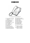
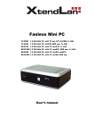
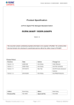
A830 SBC AMD Geode LX 800 3.5” SBC, Ultra Low Power, Fanless Design with CPU, UXGA/LCD, 10/100 Ethernet and Mini-PCI Interface. USER MANUAL Version 1. 0 IMPORTANT NOTICE : The Euro CLS A830 motherboard can be used for a large range of panel PC's from 8.4" to 42". In order to know the complete range of products we propose, please clic this link : http://www.eurocls.com/product/Panel_PC/AMD_Geode_LX_Single_LAN/ ZI de St Génault 16 rue Jean Mermoz 91080 Courcouronnes France Tél : +33 (0) 1 60 78 97 93 Fax : +33 (0) 1 60 79 14 88 Web : www.eurocls.com FCC Statement This device complies with part 15 FCC rules. Operation is subject to the following two conditions : This device may not cause harmful interference. This device must accept any interference received including interference that may cause undesired operation. This equipment has been tested and found to comply with the limits for a class "a" digital device, pursuant to part 15 of the FCC rules. These limits are designed to provide reasonable protection against harmful int erference when the equipment is operated in a commercial environment. This equipment generates, uses, and can radiate radio frequency energy and, if not installed and used in accordance with the instruction manual, may cause harmful interference to radio c ommunications. Operation of this equipment in a residential area is likely to cause harmful interference in which case the user will be required to correct the interference at hi m own expense. A830 SBC User Manual II Copyright Notice ALL RIGHTS RESERVED. No part of this document may be reproduced, copied, translated, or transmitted in any form or by any means, electronic or mechanical, for any purpose, without the prior written permission of the original manufacturer. Trademark Acknowledgement Brand and product names are trademarks or registered trademarks of their respective owners. Disclaimer We reserve the right to make changes, without notice, to any product, including circuits and/or software described or contained in this manual in order to improve design and/or performance. We assume no responsibility or liability for the use of the described product(s), conveys no license or title under any patent, copyright, or masks work rights to these products, and makes no representations or warranties that these products are free from patent, copyright, or mask work right infringement, unless otherwise specified. Applications that are described in this manual are for illustration purposes only. We make no representation or warranty that such application will be suitable for the specified use without further testing or modification. Warranty We warrant that each of its products will be free from material and workmanship defects for a period of one year from the invoice date. If the customer discovers a defect, We will, at its option, repair or replace the defective product at no charge to the customer, provided it is returned during the warranty period of one year, with transportation charges prepaid. The returned product must be properly packaged in its original packaging to obtain warranty service. If the serial number and the product shipping data differ by over 30 days, the in-warranty service will be made according to the shipping date. In the serial numbers the third and fourth two digits give the year of manufacture, and the fifth digit means the month (e. g., with A for October, B for November and C for December). For example, the serial number 1W07Axxxxxxxx means October of year 2007. A830 SBC User Manual III Packing List Before using A830 SBC, please make sure that all the items listed below are present in your package: 1 x A830 Motherboard 1 x User Manual 1 x User’s Manual & Driver CD 1 x 44pin HDD IDE Cable 1 x RS232 Cable 1 x Y Cable For Keyboard/Mouse If any of these items are missing or damaged, contact your distributor or sales representative immediately. Customer Service We provide service guide for any problem as follow steps:First, visit the website at to find the update information about the product. Second, contact with your distributor, sales representative, or our customer service center for technical support if you need additional assistance. You may have the following information ready before you call: Product serial number Peripheral attachments Software (OS, version, application software, etc.) Description of complete problem The exact wording of any error messages In addition, free technical support is available from our engineers every business day. We are always ready to give advice on application requirements or specific information on the installation and operation of any of our products. Please do not hesitate to call or e-mail us. A830 SBC User Manual IV Safety Precautions Warning! Always completely disconnect the power cord from your chassis whenever you work with the hardware. Do not make connections while the power is on. Sensitive electronic components can be damaged by sudden power surges. Only experienced electronics personnel should open the PC chassis. Caution! Always ground yourself to remove any static charge before touching the CPU card. Modern electronic devices are very sensitive to static electric charges. As a safety precaution, use a grounding wrist strap at all times. Place all electronic components in a static-dissipative surface or static -shielded bag when they are not in the chassis. A830 SBC User Manual V Revision History Version Date 1.0 2006.07.25 First Version Tin Lai 2007.11.19 Revise 2.6.4 Aladin Huang A830 SBC User Manual Note VI Author Contents CHAPTER 1 GENERAL INFORMATION .................................................................................... 2 1.1 INTRODUCTION ....................................................................................................................... 2 1.2 FEATURE ................................................................................................................................ 2 1.3 A830 SBC SPECIFICATIONS .................................................................................................... 3 1.4 A830 SBC FUNCTION BLOCK ................................................................................................ 4 1.5 A830 SBC BOARD DIMENSIONS ............................................................................................. 5 CHAPTER 2 INSTALLATIONS ..................................................................................................... 7 2.1 MEMORY MODULE(SODIMM)INSTALLATION .................................................................. 7 2.2 I/O EQUIPMENT INSTALLATION .............................................................................................. 8 2.3 JUMPERS AND CONNECTORS ................................................................................................... 9 2.4 JUMPER SETTING .................................................................................................................. 11 2.5 CONNECTORS AND PIN ASSIGNMENT .................................................................................... 13 CHAPTER 3 AWARD BIOS SETUP ............................................................................................ 22 3.1 STARTING SETUP .................................................................................................................. 22 3.2 AWARD BIOS SETUP ............................................................................................................ 23 3.3 STANDARD CMOS FEATURES .............................................................................................. 25 3.4 ADVANCED BIOS FEATURES ................................................................................................ 28 3.5 ADVANCED CHIPSET FEATURES ............................................................................................ 30 3.6 INTEGRATED PERIPHERALS ................................................................................................... 32 3.7 POWER MANAGEMENT SETUP .............................................................................................. 33 3.8 PNP/PCI CONFIGURATION SETUP ......................................................................................... 34 3.9 PC HEALTH STATUS.............................................................................................................. 35 3.10 LOAD FAIL-SAFE DEFAULTS ................................................................................................. 36 3.11 LOAD OPTIMIZED DEFAULTS ................................................................................................ 36 3.12 SUPERVISOR / USER PASSWORD SETTING ............................................................................. 37 3.13 SAVE & EXIT SETUP ............................................................................................................. 38 3.14 EXIT WITHOUT SAVING ........................................................................................................ 39 CHAPTER 4 CHIPSET DRIVER INSTA LLATION .................................................................. 41 4.1 STANDARD CMOS FEATURES .............................................................................................. 41 4.2 FURTHER INFORMATION ....................................................................................................... 43 CHAPTER 5 ETHERNET DRIVER INSTALLATION .............................................................. 45 5.1 INTRODUCTION ...................................................................................................................... 45 5.2 INSTALLATION OF ETHERNET DRIVER .................................................................................... 46 A830 SBC User Manual VII 5.3 FURTHER INFORMATION .......................................................................................................... 47 CHAPTER 6 VGA DRIVER INSTALLAT ION ........................................................................... 49 6.1 INTRODUCTION ....................................................................................................................... 49 6.2 INSTALLATION OF VGA DRIVER .............................................................................................. 49 6.3 FURTHER INFORMATION .......................................................................................................... 51 CHAPTER 7 AUDIO DRIVER INSTALL ATION....................................................................... 53 7.1 INTRODUCTION ....................................................................................................................... 53 7.2 INSTALLATION OF AUDIO DRIVER............................................................................................ 54 7.3 FURTHER INFORMATION .......................................................................................................... 56 A830 SBC User Manual VIII CHAPTER General Information 1 This chapter includes A830 Motherboard background information. Sections include: A830 SBC Introduction A830 SBC Feature A830 SBC Specifications A830 SBC Function Block A830 SBC Board Dimensions A830 SBC User Manual 1 Chapter 1 General Information 1.1 Introduction The A830 is high performance, fanless, low power PC with AMD CS 5536 chipset. The AMD LX 800 fanless, high performance CPU delivers the most performance per watt available in the market. The A830 is designed to satisfy most of the applications in the industrial market, such as POS, KIOSK, Industrial Automation, Programmable Control System, and HMI. It’s a Embedded system with DDR SDRAM, VGA/LCD controller, four COM ports, and on-board 10/100Mpbs Base-T Ethernet. The A830 supports one Mini-PCI expansion slot for Wireless, Ethernet, COM port, VGA solutions, and one CF socket for function upgrade. It is a compact design to meet the demanding performance requirements of today’s business and industrial applications. 1.2 Feature 3.5-inch Form Factor ( 146mm x 101mm) AMD LX800 500MHz CPU, Fanless Design Highest Performance Per Watt (CPU core power) AMD CS5536 Chipset Integrated TFT LCD Interface/ VGA Function 1 x DDR SODIMM, max. 1 GB Integrated 10 / 100 Mbps Base T Ethernet 1 x Mini PCI, 1 x Type I/II CF socket, 4 x COM, 4 x USB2.0 A830 SBC User Manual 2 1.3 A830 SBC Specifications CPU: AMD Embedded LX -800 Micro-processor, Ultra-low power about 3.9 Watts Chips set: AMD CS5536 Companion Device BIOS : AWARD Flash memory System memory: One 200 -pin SODIMM socket accepts up to 1GB SDRAM Enhanced IDE interface : Supports up one channel two IDE devices BIOS auto-detected for UDMA100 mode(ATA-5) One 44pins hard disk interface Serial Ports: One serial RS-232 port Three serial RS-232 pin headers, one for RS-232/422/485 jumper. Keyboard/mouse connector: Mini -DIN connector supports PS/2 interface USB interface : Two USB ports onboard, two USB pin header Video interface: Chipset : LX-800 including Display type: Support CRT and TTL LCD displays Available to support LVDS LCD via TTL to LVDS Converter Board CRT and flat panel can display simultaneously Panel resolution support up to 1280 x 1024 @18bpp or 24bpp Audio function: Chipset: Realtek ALC203 AC97 compliant interface Audio interface: Microphone in, Line in, Earphone out Ethernet interface Chipset: Realtek RTL8100C L-LF Ethernet interface : PCI 10/100 Mbps Ethernet protocol compatible Connection: On-board RJ-45 connector Mechanical and environmental (board level) Dimensions (L x W) : 145 mm x 102 mm(5.9” x 4.2”) Power supply voltage: +8 ~ +19Volts DC -input Power consumption (typical): +19V/5A@7Watts Operating temperature: 0 deg. C to 55 deg. C Operating Humidity: 30% ~ 90% Relative non-condensing A830 SBC User Manual 3 humidity, 1.4 A830 SBC Function Block A830 SBC User Manual 4 1.5 A830 SBC Board dimensions A830 SBC User Manual 5 CHAPTER Installations 2 This chapter provides information on how to use the jumps and connectors on the A830 Motherboard. The Sections include: Memory Module Installation I / O Equipment Installation Setting the Jumpers Connectors on A830 Motherboard A830 SBC User Manual 6 Chapter 2 Installations 2.1 Memory Module(SODIMM)Installation The A830 Motherboard provides one 200 -pin SODIMM slot. The socket supports up to 1GB DDR 400 SDRAM. When installing the Memory device, please follow the steps below: Step.1. Firmly insert the SODIMM at an angle into its slot. Align the SODIMM on the slot such that the notch on the SODIMM matches the break on the slot. Step.2. Press downwards on SODIMM until the retaining clips at both ends fully snap back in place and the SODIMM is properly seated. Caution ! The SODIMM only fits in one correct orientation. It will cause permanent damage to the development board and the SODIMM if the SODIMM is forced into the slot at the incorrect orientation. A830 SBC User Manual 7 2.2 I/O Equipment Installation 2.5.1 PS/2 Keyboard and PS/2 Mouse The Motherboard provides a Mini-DIN connector supports PS/2 interface. Mini -DIN connector supports Keyboard and Mouse through Y cable. Please plug keyboard or mouse directly with Y cable. In other cases, especially in embedded applications, a mouse is not used. Therefore, the BIOS stan dard setup menu allows you to select* “All, But Keyboard” under the “Halt On”. This allows no -keyboard operation in embedded system applications without the system halting under POST. 2.5.2 Audio function The AC’97 capabilities are provided by a Realtek ALC203 chip supporting digital audio outputs. The onboard ALC203 is a 20 -bit DAC and 18-bit ADC supporting full-duplex AC’97 2.3 compatible stereo audio CODEC for multimedia, including host/soft audio based designs. The audio interface includes two jacks: microph one-in and line-out. 2.5.3 Serial COM ports One RS-232 ports with 16C550 UART (or compatible) with 16 -byte FIFO buffer. Three optional COM ports support RS -232. When an optional touch -screen is ordered with PPC, serial com port can connect to a serial or an opt ional touch-screen. One optional COM port supports RS232/422/485 choice through jumper setting. 2.5.4 Ethernet interface The Motherboard is equipped with Realtek RTL8100CL -LF chipset which is fully compliant with the PCI 10/100 Mbps Ethernet protocol compatible . It is supported by major network operating systems. The Ethernet port provides a standard RJ -45 jack. 2.5.5 USB ports Four USB (Two is optional) device may be connected to the system though an adapter cable. Various adapters may come with USB ports. USB usual ly connect the external system to the system. The USB ports support hot plug -in connection. Whatever, you should install the device driver before you use the device. 2.5.6 External VGA The Motherboard has one VGA port that can be connected to an external CRT/ L CD monitor. Use VGA cable to connect to an external CRT / LCD monitor, and connect the power cable to the outlet . The VGA connector is a standard 15 -pin D-SUB connector. A830 SBC User Manual 8 2.3 Jumpers and Connectors Locating Jumpers and Connectors (front side) A830 SBC User Manual 9 Locating Jumpers and Connectors (rear side) A830 SBC User Manual 10 2.4 Jumper Setting A pair of needle-nose pliers may be helpful when working with jumpers. If you have any doubts about the best hardware configuration for your application, contact your local distributor or sales representative before you make any changes. Generally, you simply need a standard cable to make most connections. The following tables list the function of each of the board's jumpers. Label Function Note J5 Clear CMOS 3x1 header, pitch 2.0mm JP10 LCD Panel Voltage Select 3x1 header, pitch 2.0mm JP13 RS232/422/485 Selector 3x4 header ,pitch 2.0mm JP14 RS232/422/485 Selector 2x3 header ,pitch 2.0mm JP15 IDE/CF Voltage Selector 3x1 header, pitch 2.0mm 2.4.1 J5: Clear CMOS User must make sure the power supply to turn off the power supply before setting Clear CMOS. Users remember to setting jumper back to Normal before turning on the power supply. Normal Clear CMOS 1 1 2 2 3 3 Functions Normal Clear CMOS Pin# 1 Short 2 2 Short 3 2.4.2 JP10: LCD Panel Voltage Select JP10 can be configured to operate in 3.3Volts / 5Volts mode. 3.3Volts 1 2 3 Pin# 1 Short 2 2 Short 3 A830 SBC User Manual 5Volts 1 2 3 Functions 3.3Volts Selected 5Volts Selected 11 2.4.3 JP13& JP14: RS232 / RS422 / RS485 Selector The jumper can be configured to operate in RS -232/422/485 mode. JP13 RS232 3 6 RS422 / 485 9 3 11 6 9 11 1 10 1 4 7 10 RS232 1-2 4-5 7-8 10-11 RS422/485 2-3 5-6 8-9 11-12 JP14 RS232 RS422 Pin# 1-2 3-4 5-6 Function RS 232 RS 422 RS 485 RS485 2.4.4 JP15: IDE / CF Voltage Selector JP15 can be configured to operate in 5Volts / 3.3Vol ts mode. Select 5V when connect to HDD device, and select 3.3V when connect to Compact Flash device. 5.0 Volts 3.3 Volts 1 1 2 Pin# 1 Short 2 2 Short 3 A830 SBC User Manual 3 2 3 Functions 5 Volts Selected 3.3 Volts Selected 12 2.5 Connectors and Pin Assignment The table below lists the function of each of the board’s connectors. Label Function Note CN2 Inverter connector JST-B7B-PH-KL CN3 K/B Mouse connector 6-pin Mini Din CN4 TFT LCD Output Connector DF13-40DP-1.25V CN5 VGA connector D-sub 15-pin ,female CN9 Mini-PCI 124pin Mini-PCI connector JP9 External VR JST-B3B-PH-KL CON1 Ethernet connector RJ-45 LAN connector J1 DC Input connector 2.5Φ DC Jack J7 SODIMM connector SODIMM connector P1 Serial port 1 connector D-sub 9-pin , male J10 Serial port 2 connector 5x2 header ,pitch 2.54mm J9 Serial port 3 connector 5x2 header ,pitch 2.54mm J12 Serial port 4 connector 5x2 header ,pitch 2.54mm JUSB1 USB connector 1& 2 Dual USB Connector J11 Extend USB connector DF11-8DP-2DSA J14 Audio output connector DF11-10DP-2DSA J15 System Function Connector 1 JST-B10B-PH-KL J16 RTC BAT. connector DF-13-2P-1.25H J17 Primary IDE connector 22x2 header ,pitch 2.0mm J18 CF card socket Compact Flash Type II connector J21 5V/12V output connector DF11-8DP-2DSA J22 12V output connector JST-B2B-PH-KL J23 J24* 5V output connector External DC input connector JST-B2B-PH-KL DF11-8DP-2DSA * Not Default Connector and J24 connector is used for Panel PC system. A830 SBC User Manual 13 2.5.1 CN2: Inverter Connector JST-B7B-PH-KL □ □ □ □ □ 1 Pin No. 1 2 3 4 5 6 7 □ □ 7 SYMBOL +12 Volts +12 Volts +12 Volts Ground Brightness Control Ground On/Off 2.5.2 CN4: TFT LCD Output Connector Hirose_DF13-40DP-1.25V Pin No. 1 3 5 7 9 11 13 15 17 19 21 23 25 27 29 31 33 35 37 39 SYMBOL GND R1 R3 R5 R7 GND G1 G3 G5 G7 GND B1 B3 B5 B7 GND Panel Power Panel Power Panel Power GND A830 SBC User Manual Pin No 2 4 6 8 10 12 14 16 18 20 22 24 26 28 30 32 34 36 38 40 14 SYMBOL GND R0 R2 R4 R6 GND G0 G2 G4 G6 GND B0 B2 B4 B6 GND V-Sync H-Sync PDE PCLK 2.5.3 JP9: External Brightness VR Hirose_JST-B3B-PH-KL □ □ 1 Pin No. 1 2 3 □ 3 SYMBOL 5 Volts VR Out GND 2.5.4 J9: Serial Port 3 Connector 2x5 pin header, pitch 2.54 mm □ □ □ □ □ □ □ □ □ □ 1 Pin No. 1 2 3 4 5 6 7 8 9 10 A830 SBC User Manual 9 SYMBOL CD# DSR RX RTS TX CTS DTR RI GROUND N.C. 15 2.5.5 J10: Serial Port 2 Connector 2x5 pin header, pitch 2.54 mm □ □ □ □ □ □ □ □ □ □ 1 9 Pin No. 1 2 3 4 5 6 7 8 9 10 SYMBOL CD# DSR RX RTS TX CTS DTR RI GOUND N.C. 2.5.6 J12: Serial Port 4 Connector 2x5 pin header, pitch 2.54 mm □ □ □ □ □ □ □ □ □ □ 1 Pin No. 1 2 3 4 5 6 7 8 9 10 SYMBOL( RS-232) CD# DSR RX RTS TX CTS DTR RI GOUND N.C. A830 SBC User Manual 9 SYMBOL( RS-422 ) TX- SYMBOL( RS-485) DX- TX+ DX+ RX+ RXGOUND N.C. GOUND N.C. 16 2.5.7 J11: Extend USB Port Connector DF11-8DP-2DSA Pin No. 1 2 3 4 5 6 7 8 SYMBOL USB # 3 +5V USB # 4 +5V Data 3 Data 4 Data 3 + Data 4 + USB # 3 Ground USB # 4 Ground 2.5.8 J14: Audio Connector DF11-10DP-2DSA Pin No. 1 2 3 4 5 6 7 8 9 10 A830 SBC User Manual SYMBOL Line Out R Line Out L Ground Ground Line_in R input Line_in L input Mic. Input Mic. Vref N.C. N.C. 17 2.5.9 J15: System Function Connector JST-B13B-PH-KL Pin No. 1 2 3 4 5 6 7 8 9 10* 11* 12* 13* SYMBOL PWR Button Ground Reset Button HD Led 5V HD LED# PWR LED 5V Ground Volume Control + Volume Control Brightness Control + Brightness Control - *Not Default Setting 2.5.10 J16: RTC BAT. Connector DF-13-2P-1.25H Pin No. 1 2 A830 SBC User Manual SYMBOL Ground Battery +3.0V 18 2.5.11 J17: IDE Connector Pin No. 1 3 5 7 9 11 13 15 17 19 21 23 25 27 29 31 33 35 37 39 41 43 SYMBOL RST D7 D6 D5 D4 D3 D2 D1 D0 GND DREQ IOW# IOR# IORDY# DACK# IRO14 A1 A0 CS#1 ASP# +5V GND Pin No 2 4 6 8 10 12 14 16 18 20 22 24 26 28 30 32 34 36 38 40 42 44 2.5.12 J21: 5V/12V Output Connector DF11-8DP-2DSA Pin No. 1 2 3 4 5 6 7 8 A830 SBC User Manual SYMBOL 12V 12V GND GND GND GND 5V 5V 19 SYMBOL GND D8 D9 D10 D11 D12 D13 D14 D15 N.C. GND GND GND CSEL# GND N.C. D66DET# A2 CS#3 GND +5V N.C. 2.5.13 J22: 12V Output Connector JST-B2B-PH-KL Pin No. 1 2 SYMBOL 12V GND 2.5.14 J23: 5V Output Connector JST-B2B-PH-KL Pin No. 1 2 A830 SBC User Manual SYMBOL 5V GND 20 This chapter describes how to set BIOS configuration A830 SBC User Manual 21 CHAPTER Award BIOS Setup 3 Chapter 3 3.1 Award BIOS SETUP Starting Setup AwardBIOS™ has a built -in setup program that allows users to modify the basic system configuration. The information is stored in battery -backed Flash so that it retains the setup information even if the system power is turned off. Note: Values for the various setup items that appear on your own screen (including default values) may not be the same as the values shown on the screen figures in this chapter. This is because the BIOS is revised and updated from time to time. If in doubt, check Winmate website for the latest BIOS versions and related information. The system BIOS is managing and executing a variety of hardware related functions in the system, including: System date and time Hardware execution sequence Power management function Allocation of system resources A830 SBC User Manual 22 3.2 Award BIOS Setup Once you enter the Award BIOS™ CMOS Setup Utility, the Main Menu will appear on the screen. The Main Menu allows you to select from several setup functions and two exit choices. User the arrow keys to select among the items and press <Enter> to accept and enter the sub-menu. The BISO Setup Main Menu screen is shown above. Note that a brief description of each highlighted selection appears at the bottom of the screen. Setup Items The main menu includes the following main setup categories. Standard CMOS Features This menu displays the basic information about your system. Advanced BIOS Features Use this menu to set the advanced features available on your system. Advanced Chipset Features Use this menu to change the values in the chipset registers and optimize your system’s performance. Integrated Peripherals Use this menu to specify your setting for integrated peripherals. Power Management Setup Use this menu to specify your setting for power management. A830 SBC User Manual 23 PnP/PCI Configurations This option configures how PnP (Plug and Play) and PCI expansion cards operate in your system. PC Health Status This entry shows the current system temperature and voltage. Load Fail-Safe Defaults Use this menu to install fail -safe defaults for all appropriate items in the setup utility. Load Optimized Defaults Use this menu to install optimized defaults for all appropriate items in the setup utility. Set Supervisor/User Password Use this menu to change, set, or disable superviso r/user password. allows you to limit access to the system and Setup, or only to Setup. It Save & Exit Setup Save the changes that you have made in the Setup Utility and exit the Setup Utility. Exit Without Saving Abandon all changes that you have made i n the Setup Utility and exit the Setup Utility. A830 SBC User Manual 24 3.3 Standard CMOS Features The Standard CMOS Features Setup allows users to configure system components such as date, time, hard disk drive, floppy drive and display. Use the arrow keys to highlight the item and then use the <Page Up> or <Page Down> keys to select the value you want in each item. The standard CMOS Features screen is shown above. Follow each item: Date (mm : dd : yy) Set the system date. Note that if you are running a Windows OS, this ite m are automatically updated whenever you make changes to the Windows Date. Time (hh : mm : ss) Set the system time. The time is converted based on the 24 -hour military-time clock. For example, 5:00:00 p.m. is 17:00:00. IDE Primary Mater/Salve Press <Enter> to enter the sub-menu to detailed options. Video This item defines the video mode of the system. Leave this item at the default value. The choice: ”EGA/VGA*”, ”CGA 40”, ”CGA 80”, or ”MONO”. * default value A830 SBC User Manual 25 Halt On This item defines the operation of the system POST (Power -On Self Test) routine. You can use this item to select which situation you want the BIOS to stop the POST process and notify you. The choice: “All errors”, “No Errors” or, “All, but keyboard”. Base Memory/Extended Memor y/Total Memory These items are automatically detected by the system at start up time. These are display-only fields. You can not make change to these fields. Follow steps as IDE adapter below: IDE Adapters The IDE adapters control the hard disk drive . Use a separate sub-menu to configure each hard disk drive. IDE HDD Auto-Detection Press <Enter> to auto-detect HDD on this channel. If detection is successful, it fills the remaining fields on this menu. IDE Primary Master/Slave Selecting ‘Manual’ lets you set the remaining fields on this screen and select the type of fixed disk. The choice: None, Auto, or Manual Choose the access mode for this hard disk. The choice: ”CHS”, ”LBA”, ”Large”, or ”Auto”. Capacity Note that the disk drive capacity (approx.) is usually slightly greater than the size of a formatted disk given by a disk checking program. Cylinder Set the number of cylinders for this hard disk. Min = 0, Max = 65535 Head Set the number of read/write heads Min = 0, Max = 255 Precomp Warning: Setting a value of 65535 means no hard disk. Min = 0, Max =65535 Landing Zone Set the Landing Zone size. A830 SBC User Manual 26 Min = 0, Max = 65535 Sector Number of sector per-track. Min = 0, Max = 255 A830 SBC User Manual 27 3.4 Advanced BIOS Features This section allows you to configure your syst em for basic operation. You have the opportunity to select the system’s default speed, boot -up sequence, keyboard operation, shadowing and security. Removable Device Priority You can choose the priority of your Removable Device The choice: USB-FDD0, USB-ZIP0, Floppy Disks, ZIP100, Floppy Disks Hard-Disk Boot Priority You can choose the priority of your Hard Disk The choice: Pri.Master, Pri.Slave, USBHDD0, Bootable Add -in Cards CD-ROM Boot Priority You can choose the priority of your Removable Device The choice: Pri.Master, Sec.Slave, USB -CDROM1,USB-CDROM0, Virus Warning Allow you to choose the Virus Warning feature for IDE Hard Disk boot sector protection. Enable this item to prevent someone from writing data into this area. The choice: Enabled or Disa bled Default: Disabled CPU Internal Cache All processors that can be installed in this motherboard use internal level of L1 cache memory to improve performance. Leave this item at the default value for better performance. A830 SBC User Manual 28 The choice: Enabled or Disabled Default: Enabled Quick Power On Self Test Enable this item to shorten the power on testing (POST) and have your system start up faster. You might like to this item after you are confident that your system hardware is operating smoothly. The choice: Enabled or Disabled Default: Enabled Note: If customers need to use USBHDD for booting an operating system at start-up time, then you must disable the “Quick Power On Self Test “. First/Second/Third Boot Device Use these items to select the priority and order of the devices that your system searches for an operating system at start -up time. The choice: Removable, Hard Disk, CDROM, LAN, Disabled Default: Hard Disk (First) / CDROM (Second) / Removable (Third) Boot Other Device If you enable this item, the system s earches all other possible locations for and operating system if it fails to find one in the devices specified under the First, Second and the Third boot devices. The choice: Enabled or Disabled Default: Enabled Boot Up NumLock Status This item defines if the keyboard NumLock key is active when your system is started. The choice: On or Off Default: On Security Option If you have installed password protection, this item defines if the password is required at system start up, or if it is only required with a user tries to enter the Setup Utility. The choice: Setup or System Default: Setup A830 SBC User Manual 29 3.5 Advanced Chipset Features These items define critical timing parameters of the mainboard. You should leave the items at their default values unless you are very familiar wi th the technical, specifications of your system hardware. If you change the values incorrectly, you may introduce fatal error or recurring instability into your system. CPU Frequency This item allows you to select CPU and Memory Frequency. If this item has been set as Auto, the Memory Frequency will be set to sequent with CPU Frequency. When this item is not selected as Auto, Memory Frequency will be able for selection. The CPU Frequency choice: Auto, 200MHz, 333MHz, 400MHz, 433MHz, or 500MHz. Default: Auto Video Memory Size This item allows you select Video Memory Size The choice: 32M, 64M, 128M, or 254M Default: 32M Output Display This item allows you select Output Display The choice: Flat Panel, CRT, or Panel & CRT Default: Panel & CRT A830 SBC User Manual 30 Flat Panel Type This item allows you select the resolution of the Display. Resolution: 640 x 480 800 x 600 1024 x 768 1280 x 1024 Default: 640x480 Onboard Audio This item allows you to control the Onboard Audio The choice: Enabled or Disabled Default: Enabled Onboard USB2.0 This item allows you to control the Onboard USB The choice: Enabled or Disabled Default: Enabled A830 SBC User Manual 31 3.6 Integrated Peripherals On-Chip IDE Channel 1 The chipset contains a PCI IDE interface with support IDE channel. By default to activate the primary/secondary IDE interface. Master/Salve Drive PIO Mode The four IDE PIO (Programmed Input/Output) fields let you set a PIO mode (0-4) for each of the four IDE devices that the onboard IDE interface supports. Mode 0 through 4 provides successively in creased performance. In Auto mode, the system automatically determines the best mode for each device. The choice: Auto, Mode 0, Mode 1, Mode 2, Mode 3, or Mode 4 Default: Auto Onboard LAN Boot ROM By default, this setting is disable d. Onboard Serial Port 1/2/3/4 This option is used to assign the I/O address and Interrupt Request (IRQ) for the onboard Serial Port. The choice: Disabled, 3F8/IRQ4, 2F8/IRQ3, 3E8/IRQ7, 2E8/IRQ5 Default: 3F8/IRQ4 (Port1), 2F8/IRQ3 (Port2), 3E8/IRQ7 (Port3), 2E8/IRQ5 (Port4) A830 SBC User Manual 32 3.7 Power Management Setup The Power Management Setup allows you to configure your system to most effectively saving energy while operating in a manner consistent with your own style of computer use Power Management This item defines the ACPI(Advanced Con figuration and Power Management) feature that makes hardware status information available to the operating system, enable a PC to turn its peripherals on or off for improving the power management, and allows a PC turned on or off by external devices, so that a mouse or keyboard can wake up it. The choice: ACPI Default: ACPI Soft-Off by PWR-BTTN Under ACPI you can create a software power down. In a software power down, the system can be resumed by Wake -Up Alarm. This item lets you install a software power d own that is controlled by the power button on your system. If the item is set to Instant -Off, then the power button causes a software power down. If the item is set to Delay 4 seconds, then you have to hold the power button down for 4 seconds to cause a s oftware power down. The choice: Delay 4 Sec. or Instant -Off Default: Instant-Off A830 SBC User Manual 33 Power-On by Alarm When set to ‘Enabled’, the following three fields become available and you can set the date, hour, and minute to turn on your system. The choice: Enabled or Disabled Default: Disabled Time (hh : mm : ss) of Alarm This item selects the alarm Time. [hh]: key in a DEC number; Min = 0, Max = 23. [mm] : key in a DEC number; Min = 0, Max = 59. [ss]: key in a DEC number; Min = 0, Max = 59 . PWRON After PWR-fail Select the item “On”, the system can be reboot automatically when power fail. Select “Former-Sts” will follow former setting. Select “Off”, you need to reboot the system manually. 3.8 The choice: Off, On, Former-Sts Default: Off PnP/PCI Configuration Setup PNP OS Installed Select ‘Yes’ if you are using a Plug and Play capable operating system. Select ‘No’ if you need the BIOS to configure non -boot devices. A830 SBC User Manual 34 3.9 PC Health Status This section shows the status of Temperature,& System Voltage status Shutdown Temperature This item allows you to select the shutdown temperature. The system will automatically shutdown while the CPU temperature has reach to the value you have set. The choice: 60∘ C/140∘ F, 65∘ C/149∘ F, 70∘ C/158∘ F, or Disabled The following items provide you with information about the system’s current operating status. You can not make changes to one of them. System Temperature CPU temperature VCCP Vmem +5V +12V ` A830 SBC User Manual 35 3.10 Load Fail-Safe Defaults When you press <Enter> on this item, you will get confirmation dialog box with a message similar to: Load Fail-Safe Defaults (Y/N)? N Pressing ‘Y’ loads the BIOS default values for the most stable, minimal performance system operations. 3.11 Load Optimized Defaults When you press <Enter> on this it em, you will get confirmation dialog box with a message similar to: Load Optimized Defaults (Y/N)? N Pressing ‘Y’ loads the default values that are factory -set for optimal performance system operation. A830 SBC User Manual 36 3.12 Supervisor / User Password Setting Steps to set supervisor/user password are described as follows: New password setting: 1. While pressing <Enter> to set a password, a dialog box appears to ask you enter a password. 2. Key in a new password. The password can not exceed eight characters. 3. Please Enter Your Password System will request you to confirm the new password again. 4. Please Confirm Your Password When completed, new code takes effect. No Password Setting: If you wants to disable the password, just <Enter> as a password input is requested. If you forget password: If you forget the password, the only way to access the system is to clear the CMOS memory. You may remove the battery from motherboard and put it back to clear the setting. A830 SBC User Manual 37 3.13 Save & Exit Setup Pressing <Enter> on this item asks for confirmation: Save to CMOS and Exit (Y/N)? Y Press ‘Y’ stores the selections made in the menus of CMOS – a special section of memory that recorded in after you turn your system off. The next time you turn on your computer, the BIOS co nfigures your system according to the Setup selections recorded in he CMOS memory of the chipset. After saving the values the system is restarted again. A830 SBC User Manual 38 3.14 Exit Without Saving Press <Enter> on this item asks for confirmation: Quit Without Saving (Y/N)? Y This allows you to exit from Setup without storing in CMOS any change. The previous selections remain in effect. This exits from Setup utility and restarts your computer. A830 SBC User Manual 39 CHAPTER 4 Chipset Driver Installation This chapter offers informatio n on the chipset software installation utility. Sections include: Installation of Chipset Utility Further Information A830 SBC User Manual 40 Chapter 4 Chipset Driver Installation 4.1 Standard CMOS Features The Motherboard is equipped with AMD CS5536 Companion Device. The AMD Chipset Drivers should be installed first before the software drivers to enable Plug & Play INF support for AMD chipset components. Follow the instructions below to complete the installation. Step.1. After finishing the O.S. installation, insert the driver C D. Open the Device Manager, and select Entertainment Encryption/Decryption Controller. Click on right button and select properties. Setp.2. Go to Driver page and choose Update Driver. A830 SBC User Manual 41 Setp.3. Click Install from a list or specific location, and click on next. Step.4. Click on browse and select target folder, and click to next. A830 SBC User Manual 42 Step.5. Click Finish to finish the driver installation. 4.2 Further Information Winmate web site: http://www.winmate.com.tw A830 SBC User Manual 43 CHAPTER 5 Ethernet Driver Installation This chapter offers information on the Etherne t. Sections include: Introduction Installation of Ethernet Driver Further Information A830 SBC User Manual 44 Chapter 5 Ethernet Driver Installation 5.1 Introduction The A830 Motherboard is equipped with the Realtek RTL8100CL -LF LOM Ethernet controller combines a triple -speed IEEE 802.3 compliant Media Access Controller (MAC) with a triple-speed Ethernet transceiver, 32 -bit PCI bus controller, and embedded memory. With state -of-the-art DSP technology and mixed -mode signal technology, it offers high-speed transmission over CAT 5 UTP or CAT 3 UTP (10Mbps only) cable. Functions such as Crossover Detection & Auto -Correction, polarity correction, adaptive equalization, cross -talk cancellation, echo cancellation, timing recovery, and error cor rection are implemented to provide robust transmission and reception capability at high speeds. The Ethernet port provides a On -board standard RJ-45 connector. The device supports the PCI 10/100Mbps Ethernet interface supports for host communications with power management, and is compliant with the IEEE 802.3 specification for 10/100Mbps. A830 SBC User Manual 45 5.2 Installation of Ethernet Driver The Users must make sure which operating system you are using in the A830 Motherboard before installing the Ethernet drivers. Follow the steps below to complete the installation of the Realtek RTL8100CL -LF LAN drivers. You will quickly complete the installation. Setp.1. Insert the CD that comes with the motherboard. Open the file document “ A830_LAN_649” and click on “Setup.exe” to exe cute the setup. Setp.2. Click on “Next“ to install driver. A830 SBC User Manual 46 Setp.3. Click “Finish” and restart the computer for new settings to take effect. 5.3 Further Information The Realtek web site: http://www.realtek.com.tw Winmate web site: http://www.winmate.com.tw A830 SBC User Manual 47 CHAPTER VGA Driver Installation This chapter offers information on the VGA. Sections include: Introduction Installation of VGA Further Information A830 SBC User Manual 48 6 Chapter 6 VGA Driver Installation 6.1 Introduction The A830 Motherboard offers an on-board PCI flat panel/VGA interface. The specifications and features are described as follows: The PPC supports CRT and TFT LCD displays. In addition, it also supports CRT and flat panel display mode simultaneously. The Motherboard can be set in one of three configurations: on a CRT, on a flat panel display, or on both simultaneously. The system is initially set to simultaneous display mode. The Panel resolution supports up to 1280 x 1024 @18bpp or 24bpp. 6.2 Installation of VGA Driver To install the VGA drivers, follow the steps below to proceed with the installation. Step.1. Open the device manager, choose “VGA Controller” and click on “Properties”. A830 SBC User Manual 49 Step.2. Go to Driver page and choose “Update Driver”. Step.3. Click Install from a list or specific location, and click on “Next”. Step.4. Click on browse and select target folder, and click to ”Next”. A830 SBC User Manual 50 Step.5. Click on “Continue Anyway” to go on. Step.6. Click “Finish” to finish the driver installation. 6.3 Further information Winmate web site: http://www.winmate.com.tw A830 SBC User Manual 51 CHAPTER AUDIO Driver Installation This chapter offers information on the Audio. Sections include: Introduction Installation of AUDIO Further Information A830 SBC User Manual 52 7 Chapter 7 AUDIO Driver Installation 7.1 Introduction The Motherboard is equipped with the ALC203 is a 20 -bit DAC and 18-bit ADC full-duplex AC'97 2.3 compatible stereo audio CODEC designed for PC multimedia systems, including host/soft audio, and AMR/CNR based designs. The ALC203 incorporates proprietary converter technology to achieve a high SNR (greater than 100 dB), sensing logics for device reporting, and a Universal Audio Jack® for improved user convenience. The ALC2 03 AC'97 CODEC supports multiple CODEC extensions with independent variable sampling rates and built -in 3D effects. The ALC203 CODEC provides two pairs of stereo outputs with independent volume controls, a mono output, multiple stereo and mono inputs, alon g with flexible mixing, gain, and mute functions to provide a complete integrated audio solution for PCs. The circuitry of the ALC203 CODEC operates from a 3.3V digital and 3.3V/5V analog power supply with EAPD (External Amplifier Power Down) control for use in notebook and PC applications. The ALC203 integrates a 50mW/20Ohm headset audio amplifier into the CODEC, saving BOM costs. The ALC203 also supports the S/PDIF out function (complies with AC'97 2.3) that offers easy connection of PCs to consumer electronic products, such as AC3 decoders/speakers and mini disk devices. A830 SBC User Manual 53 7.2 Installation of Audio Driver The users must make sure which operating system you are using in the Motherboard before installing the Audio drivers. Follow the steps below to complet e the installation of the Realtek ALC203 AC97 Audio drivers. You will quickly complete the installation. Follow the steps below to install the Realtek AC97 Codec Audio Drivers. Step.1 Open the device manager, choose “Audio Controller” and click on “Properties”. Step.2 Go to Driver page and choose “Update Driver”. A830 SBC User Manual 54 Step.3 Click Install from a list or specific location, and click on “Next”. Step.4 Click on browse and select target folder, and click to “Next”. Step.5 Click on “Continue Anyway” to go on. A830 SBC User Manual 55 Step.6 Click “Finish” to finish the driver installation. 7.3 Further Information Winmate web site: http://www.winmate.com.tw A830 SBC User Manual 56 Copyright Notice Copyright © 2007 Winmate Communication Inc. , ALL RIGHTS RESERVED. No part of this document may be reproduced, copied, translated, or transmitted in any form or by any means, electronic or mechanical, for any purpose, without the prior written permission of the original manufacturer. Trademark Acknowledgement Brand and product names are trademarks or r egistered trademarks of their respective owners. A830 SBC User Manual 57