1
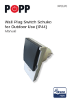
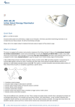
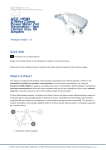
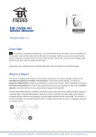
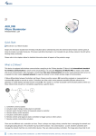
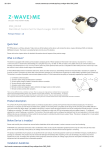
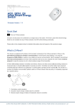
DUW_054313
Wall Switch Set for Design
Duwi Everlux
Firmware Version : 1.0
Quick Start
A This device is a Z-Wave actuator. Triple click one of the buttons on the device will include the device.
A green blinking of LED will indicate successful inclusion. The device is excluded by triple click to one of the
buttons.
Please refer to the chapters below for detailed information about all aspects of the products usage.
What is Z-Wave?
This device is equipped with wireless communication complying to the Z-Wave standard. Z-Wave is the
international standard for wireless communication in smart homes and buildings. It is using the
frequency of 868.42 MHz to realize a very stable and secure communication. Each message is reconfirmed
(two-way communication) and every mains powered node can act as a repeater for other nodes (meshed
network) in case the receiver is not in direct wireless range of the transmitter.
Z-Wave differentiates between Controllers and Slaves. Slaves are either sensors (S) transmitting metered or
measured data or actuators (A) capable to execute an action. Controllers are either static mains powered
controllers (C) also referred to as gateways or mobile battery operated remote controls (R). This results in a
number of possible communication patterns within a Z-Wave network that are partly or completely supported
by a specific device.
1. Controllers control actuators
2. Actuators report change of status back to controller
3. Sensors report change of status of measured values to controller
(c) 2012 Z-Wave Europe GmbH, Goldbachstr. 13, 09337 Hohenstein-Ernstthal, Germany, All rights reserved, www.zwaveeurope.com - pp 1
4.
5.
6.
7.
Sensors directly control actuators
Actuators control other actuators
Remote controls send signals to static controllers to trigger scenes or other actions
Remote controls control other actuators.
There are two different role a controller can have. There is always one single primary controller that is managing the
network and including/excluding devices. The controller may have other functions - like control buttons - as well. All other
controllers don't manage the network itself but can control other devices. They are called secondary controllers. The
image also shows that its not possible to operate a sensor just from a remote control. Sensors only communicate with
static controllers.
Product description
The Duwi Switch Flush Mountable is a wireless actuator able to switch loads up to 2300 W. The device is
delivered as a complete set with flush mountable insert, paddle and mounting frame compatible to the
design of the switching series Duwi Everlux white. The paddle of the device is used to control the device
itself . The status of the switch is indicated on a dual color LED for test purposes. This device is designed for
a 3 wire system and needs a neutral wire in the wall box.
Before Device is installed
Please read carefully the enclosed user manual before installation of the radio-actuator, in order to ensure
an error-free functioning.
ATTENTION: only authorized technicians under consideration of the country-specific installation
guidelines/norms may do works with 230?Volt mains power. Prior to the assembly of the product, the
voltage network has to be switched off and ensured against re-switching.
The product is permitted only for proper use as specified in the user manual. Any kind of guarantee claim
has to be forfeited if changes, modifications or painting are undertaken. The product must be checked for
damages immediately after unpacking. In the case of damages, the product must not be operated in any
case. If a danger-free operation of the equipment cannot be assured, the voltage supply has to be
interrupted immediately and the equipment has to be protected from unintended operation.
Installation Guidelines
The insert is designed to fit into standard circular European wall boxes with 60 mm diameter. The insert
combined with the mounting plate can be screwed in top of the wall box using the two screws delivered with
the device. The mounting frame is then attached to the mounting plate and the switch is completed by
pushing the switching paddle into the mounting frame. Mind the arrow on the inserts top side showing the
mounting direction of the insert. It is also possible to mount the insert without any local operation behind a
cover or inside a lamp. The mounting plate, frame and the switching paddle become useless in such a
scenario.
(c) 2012 Z-Wave Europe GmbH, Goldbachstr. 13, 09337 Hohenstein-Ernstthal, Germany, All rights reserved, www.zwaveeurope.com - pp 2
The schematics below shows how to wire the actuator. The two wired from the mains distribution panel are
connected to the inserts contacts N and L. The contact S is the switched contact and need to be connected
to the cable to the load. The second wire to the load is connected to N as well. Both contacts marked as N
are connected with each other.
A fuse protects the electronics of the actuator. The fuse is accessible on the top side of the device. Inside
the plug there is the working fuse plus a spare fuse.
Behavior within the Z-Wave network
I
On factory default the device does not belong to any Z-Wave network. The device needs to join an
existing wireless network to communicate with the devices of this network. This process is called Inclusion.
Devices can also leave a network. This process is called Exclusion. Both processes are initiated by the
primary controller of the Z-Wave network. This controller will be turned into exclusion respective inclusion
mode. Please refer to your primary controllers manual on how to turn your controller into inclusion or
exclusion mode. Only if the primary controller is in inclusion or exclusion mode, this device can join or leave
the network. Leaving the network - i.e. being excluded - sets the device back to factory default.
(c) 2012 Z-Wave Europe GmbH, Goldbachstr. 13, 09337 Hohenstein-Ernstthal, Germany, All rights reserved, www.zwaveeurope.com - pp 3
If the device already belongs to a network, follow the exclusion process before including it in your network.
Otherwise inclusion of this device will fail. If the controller being included was a primary controller, it has to
be reset first.
Blinking red/green LED indicates that the device is in factory reset state. Once the controller is turned into
inclusion mode triple click one of the buttons on the device will include the device. A green blinking of
LED will indicate successful inclusion that will be turned off shortly afterwards. The device is excluded by
triple click to one of the buttons when the controller is in exclusion mode.
Operating the device
The actuator is operated by the local switching paddles or wirelessly using Z-Wave commands
(communication patterns 1, 4, 5 and 7). If the insert is mounted correctly pushing the upper part of the
paddle will turn on the load; pushing the lower part of the paddle will turn off the electric load.
The device is also able to remotely operate other devices (communication pattern 5) by sending wireless ZWave commands. In case the remote device is a switch as well the remote operation is similar to the local
operation by pushing upper to lower part of the switching paddle.
Child Protection
The device can be turn into a child protection mode. In this mode all local operation is disabled.
The child protection mode MUST be turned on wirelessly. However in protected by sequence mode it is
possible to unlock the device for local operation with a triple click. The unlock state will last for 5 seconds.
LED Control
Red and green blinking continuously: Device is not included in a Z-Wave network
Red lights up for 3 seconds: Device was not included/excluded after being put into learn mode by triple
press of up/down button
Green lights up for 3 seconds: The inclusion/exclusion was successful or new association was saved
successfully
Green or no light: depending on settings of configuration parameter for LED control
Associations
A
Z-Wave devices control other Z-Wave devices. The relationship between one device controlling
another device is called association. In order to control a different device, the controlling device needs to
maintain a list of devices that will receive controlling commands. These lists are called association groups
and they are always related to certain events (e.g. button pressed, sensor triggers, ...). In case the event
happens all devices stored in the respective association group will receive a common wireless command.
(c) 2012 Z-Wave Europe GmbH, Goldbachstr. 13, 09337 Hohenstein-Ernstthal, Germany, All rights reserved, www.zwaveeurope.com - pp 4
Association Groups:
1 Basic On/Off Group (max. nodes in group: 5)
Command Classes
Supported Command Classes
Basic (version 1)
Hail (version 1)
Binary Switch (version 1)
Version (version 1)
All Switch (version 1)
Indicator (version 1)
Manufacturer Specific (version 1)
Protection (version 1)
Association (version 1)
Controlled Command Classes
Basic (version 1)
Technical Data
(c) 2012 Z-Wave Europe GmbH, Goldbachstr. 13, 09337 Hohenstein-Ernstthal, Germany, All rights reserved, www.zwaveeurope.com - pp 5
Power Supply
230V ~50-60 Hz
Attachable Loads
up to 2300 W resistive load or up to 460 VA inductive load
Fuse
Type: T 1.25 A H (Load 1.25 Ampere, high shutdown capacity), D: 5 mm,
L: 20 mm
IP Rating
IP 20
Frequency
868.42 MHz (SRD Band)
Wireless Range
up to 100 m outside, on average up to 20 m inside buildings
Explorer Frame Support
No
SDK
5.02 pl2
Device Type
Slave with routing capabilities
Generic Device Class
Binary Switch
Specific Device Class
Binary Power Switch
Routing
Yes
FLiRS
No
Firmware Version
1.0
Explanation of Z-Wave specific terms
Controller — is a Z-Wave device with capabilities to manage the network. Controllers are typically
Gateways, Remote Controls or battery operated wall controllers.
Slave — is a Z-Wave device without capabilities to manage the network. Slaves can be sensors, actuators
and even remote controls.
Primary Controller — is the central organizer of the network. It must be a controller. There can be only one
primary controller in a Z-Wave network.
Inclusion — is the process of bringing new Z-Wave devices into a network.
Exclusion — is the process of removing Z-Wave devices from the network.
Association — is a control relationship between a controlling device and a controlled device.
Wakeup Notification — is a special wireless message issued by a Z-Wave device to annonces that is is
able to communicate.
Node Information Frame — is a special wireless message issued by a Z_Wave device to announce its
capabilities and functions.
Disposal Guidelines
The product does not contain hazardous chemicals.
(c) 2012 Z-Wave Europe GmbH, Goldbachstr. 13, 09337 Hohenstein-Ernstthal, Germany, All rights reserved, www.zwaveeurope.com - pp 6
Do not dispose of electrical appliances as unsorted municipal waste, use separate collection facilities.
Contact your local government for information regarding the collection systems available. If electrical
appliances are disposed of in landfills or dumps, hazardous substances can leak into the groundwater and
get into the food chain, damaging your health and well-being.
(c) 2012 Z-Wave Europe GmbH, Goldbachstr. 13, 09337 Hohenstein-Ernstthal, Germany, All rights reserved, www.zwaveeurope.com - pp 7