1
Camera Bus
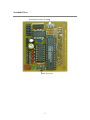
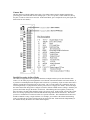
This bus interfaces with the CMOS camera chip. The CMOS camera board is mounted parallel to the
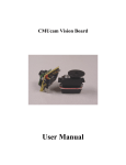
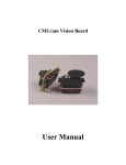
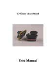
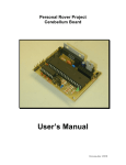
processing part of the board and connects staring at pin 1. (See cover picture) Under normal use, the top
two pins (33 and 34) of the bus are not used. In the Demo Mode, pin 33 outputs the servo pwm signal (See
demo mode for more details).
Parallel Processing in Slave Mode
The CMUcam supports a mode of operation that allows multiple boards to process data from the same
camera. If a PC104 style pass through header is used instead of the standard double row female header, it
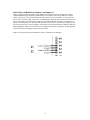
is possible to rack multiple boards along the same camera bus. Upon startup, if pin 34 on the camera bus is
pulled to ground, the board will operate in slave mode. (Pin 33 on the camera bus is pulled low while pin
34 is being checked, so a jumper between the two pins can serve to engage slave mode.) Slave mode stops
the camera board from being able to configure or interfere with the CMOS camera’s settings. Instead it just
processes the format setup by the master vision board. When linking the buses together you must only
have one master, all other boards should be setup to be in slave mode. In this current version of the system
there is no message passing between boards other than the image data from the camera bus. This means
you have to communicate to each slave board via a separate serial link. This communication to the board
should be identical to using a single CMUcam. For example, you could have the master board tracking
some color while the slave board could be told to get mean color data. Each board runs independently of
one another and only the master can control camera registers.
8