1
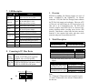
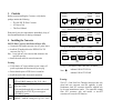
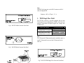
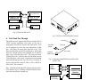
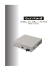
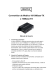
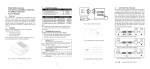
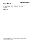
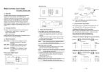
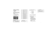
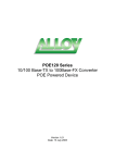
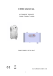
User's Manual
PoE PSE
(Power Sourcing Equipment)
Bridge Media Converter
Fast Ethernet 10/100Base-TX(RJ-45)
To 100Base-FX(ST/SC/LC)
10. PoE PSE TP-Fiber
Technical Specifications
• Standards
•
•
•
•
: IEEE802.3u 10/100Base-TX, 100Base-FX
IEEE802.3af Power over Ethernet
UTP Cable : Cat. 5 cable and up to100m
Fiber Cable :
50/125, 62.5/125 or 100/140µm multi-mode
8.3/125, 8.7/125, 9/125 or 10/125µm single-mode
PSE Power Feeding Supports :
“Endpoint” via TP pin 1, 2, 3, 6
LED Indicators :
POWER, PoE, TP LNK/ACT, 100, FX LNK/ACT,
FDX/COL,4W,7W,15.4W
Data Transfer Rate :
Speed
100Mbps
10Mbps
Forwarding Rate
148,800 PPS
14,880 PPS
PoE PSE
Bridge Media Converter
User's Manual
Release 2.0
• Flow Control : IEEE802.3x compliant for full duplex
Backpressure flow control for half duplex
• Power Requirement :
AC Line: 100-240V 50-60Hz
• Power Consumption : 24W
• Ambient Temperature : 0° to 50°C
• Humidity
: 5% to 90%
• Dimensions : 40(H) × 158(W) × 133(D) mm
• Complies with FCC Part 15 Class A and CE Mark
Note: For connecting this device to Router, Bridge or
Switch, please refer to the corresponding device's
Technical Manual.
Part Number: 620-1031-000
Release Date: May, 2005
10
User's Manual
PoE PSE
(Power Sourcing Equipment)
Bridge Media Converter
Fast Ethernet 10/100Base-TX(RJ-45)
To 100Base-FX(ST/SC/LC)
7.
LED Description
LED
FX
LNK/ACT
FX
FDX/COL
TP
LNK/ACT
TP 100
PWR
Color
Function
Lit when fiber connection is good
Green
Blinks when fiber data is present
Lit when full-duplex mode is active
Amber Off when half-duplex is active
Blinks when collision is present
Lit when TP connection is good
Green
Blinks when TP data is present
Lit when TP speed is 100Mbps
Green
Off when TP speed is 10Mbps
Green Lit when +5V power is coming up
Green
4W
Green
Lit when PoE feeding power is active
Lit when PoE feeding power is disrupted
(In case of overtemperature/overcurrent )
Light when PD Class Type is Class 1
7W
Green
Light when PD Class Type is Class 2
15.4W
Green
Light when PD Class Type is Class 0 or 3
PoE PSE-TP
Red
8. Connecting to TP, Fiber Device
Converter
TP Port
10/100TP
Converter
Fiber Port
100FX
AUTO, FORCE selectable: Bit 1, 2, 3 of S1
a. AUTO: 10/100 NWay Auto-negotiation
b. FORCE: 100 or 10, FDX or HDX
100Mbps duplex selectable: Bit 5 of S1
a. FDX for 100FDX fiber link partner, default
b. HDX for 100HDX fiber link partner
TP-AUTO 100
FDX
LFP
EN FDX-FX PoE
S1
1
RESET
2
3
TP-FORCE 10 HDX
4
5
6
LFP HDX-FX PoE
DIS
DIS
1.
Overview
IEEE802.3u 100Mbps Fast Ethernet supports two types of
media, 10/100Base-TX and 100Base-FX, for network
connection. LFP (Link Fault Pass Through) feature enhances
the TP-Fiber Link integrity and conformity. Either one of TP
or Fiber port is in link-fail state, the LFP converter forces the
other port to be at link-disabled state. The PSE media
converter complies with IEEE 802.3af, its advanced autosensing algorithm enables providing power devices (PD)
discovery, classification, current limit, and other necessary
functions. It also supports high safety with short circuit
protection and power-out auto-detection to PD.
2.
Model Description
Model
PoE PSE TP-Fiber
Power Description
AC Line: 100-240V 50-60Hz
The 100Mbps Fiber Transceiver
Wavelength
1310nm
1310nm
1550nm
∗:Any other fiber model, such as MT-RJ is available upon
request.
Single Fiber Model
TX, RX Wavelength
1310nm Single-Mode 20Km TX (Transmit)
1310nm
∗ 40/60Km models are option RX (Receive)
1550nm
1550nm Single-Mode 20Km TX (Transmit)
1550nm
∗ 40/60Km models are option RX (Receive)
1310nm
ST/SC/LC multi-mode 2Km
SC/LC.S05/S20/S40/S60Km single-mode
SC/LC.S80/S100Km single-mode
Note:
The 1310nm and 1550nm models must be installed in pairs,
i.e., install 1310nm model at one end and 1550nm model at
the other one.
Fig. 12 Reset button and S1—Bit 1, 2, 3, 4, 5, 6
Configuration and Setting
8
1
3.
Checklist
Before you start installing the Converter, verify that the
package contains the following:
⎯ The PoE PSE TP-Fiber Converter
⎯ AC Power Cord
⎯ This User's Manual
Please notify your sales representative immediately if any of
the aforementioned items is missing or damaged.
10/100
Switch
TP
●●
●
Installing the Converter
PSE TP-Fiber Converter with Powered Device (PD)
⇒ Connect the PSE media converter to an AC power source
⇒ Install the TP media cable to the IEEE 802.3af PD
converter (See Fig. 2)
Note: It can work as a pure converter that connects to the
non-PoE converter.
⇒ Install the media cable for network connection
○
⇒ Verify that the AC input conforms to your country AC
power requirement and then insert the power plug
⇒ Ensure that the power of PSE device is turned on
⇒ Install the media cable for network connection
Default: AUTO
AUTO or FORCE setting, see Fig. 12 S1—Bit 1
Attach TP Cat. 5 cable to TP port, and the distance
TP
Port can be up to 100m.
Use the straight-through cable to connect the switch
or workstation, the 10/100 TP port can support
AUTO MDI-X sensing.
Fiber Default: 100FDX
Port "100FDX"/"100HDX" setting, see Fig. 12 S1—Bit 5
2
●
●
LFP
C
Fiber
●
Cable
TP
●
A
B
TP
○○
C
Fiber
Cable
10/100
Switch
Remote
Station
LFP
●○
TP
○
●
Fig. 10 The status as TP Cable A is broken
10/100
Switch
A
B
LFP
TP
○
Warning:
Remote
Station
Fig. 9 Normal status via a pair of LFPs
10/100
Switch
LFP
4.
A
B
LFP
10/100
Switch
○○
10/100
Switch
Remote
Station
○
●
LFP
C
Fiber
Cable
TP
○○
Fig. 11 The status as Fiber Cable B or C is broken
Note : ●
○
indicates LNK/ACT LED Lit
indicates LNK/ACT LED Off
Warning:
The LFP ( Link Fault Pass Through) function works only
when both two converters own this capability in pairs.
Furthermore, both LFP converters should be supplied only
by the same manufacturer/vender. The connection coming
from LFP converters with odd models or non-LFP
converters will cease the LFP function.
7
TX-1310/RX-1550
PoE PSE TP-to-100FX
WDM Single Fiber
TX-1550/RX-1310
Single Fiber
PoE PSE TP-to-100FX
WDM SingleFiber
TP
TP
AC
PoE PD
TP
AC
TP
PoE PD
Fig. 8 Power from PSE to PD
Fig. 1 The View of PoE PSE Media Converter
6.
Link Fault Pass Through
This media converter supports link fault pass through (LFP) in
TX/FX converter application. Link status on one port is
propagated to the other port to notice the remote nodes. If TP
port is unplugged, this converter stops transmission on fiber
port. This causes the remote fiber node link to fail. LED
shows the link failure on both TP and fiber ports. If fiber link
fails, this converter restarts auto-negotiation on TP port but
always stays in the link failure state. This causes the remote
TP node link to fail. LED also shows the link failure on both
TP and fiber ports. Refer to Fig. 9 shown below for the normal
status when the link succeeds. Also refer to Fig. 10 and Fig. 11
for the erroneous status when TP Cable A, Fiber Cable B or
Fiber Cable C fails to connect.
Note: Link fault pass through (LFP) function only takes effect
as S1-Bit4 (see Fig. 12) is enabled. Disabled S1-Bit4 will turn
this media converter into a general one.
RJ-45 Jack
Fiber Optic
100FX Fiber
Network
Cat. 5 Cable
PD Device
(Refer to Fig. 6)
Fig. 2 Connection among PSE Ethernet Switch, Fiber
and TP Cables
100FX
Fiber
Network
RX
TX
TX
RX
PoE PSE TP-to-100FX
Converter
AC
PoE PD or
PoE Splitter
Fig. 3 PSE to PD or PoE Splitter
6
3
Note:
IEEE802.3af assigns pairs on the RJ-45 connector and Cat.5
cable of Endpoint PSE.
Endpoint : -48V via TP pin 1, 2, 3, 6
5.
Fig. 4 PoE PSE Media Converter Front Panel
WDM Single Fiber Model
The TP-Fiber converter is specially designed with an optic
Wavelength Division Multiplexing (WDM) model that can
transport bi-directional full duplex signal over a single fiber
simultaneously.
Single Fiber Model
1310nm Single-Mode 20Km
∗ 40/60Km models are option
1550nm Single-Mode 20Km
∗ 40/60Km models are option
TX, RX Wavelength
TX (Transmit)
1310nm
RX (Receive)
1550nm
TX (Transmit)
1550nm
RX (Receive)
1310nm
Note:
The 1310nm and 1550nm models must be installed in pairs, i.e.,
install 1310nm model at one end and 1550nm model at the
other one.
Fig. 5 PoE PSE Media Converter Rear Panel
Fig.7 PoE PSE WDM Single Fiber Converter Front Panel
Fig. 6 Endpoint PSE RJ-45 Male Connector
4
5
Note:
IEEE802.3af assigns pairs on the RJ-45 connector and Cat.5
cable of Endpoint PSE.
Endpoint : -48V via TP pin 1, 2, 3, 6
5.
Fig. 4 PoE PSE Media Converter Front Panel
WDM Single Fiber Model
The TP-Fiber converter is specially designed with an optic
Wavelength Division Multiplexing (WDM) model that can
transport bi-directional full duplex signal over a single fiber
simultaneously.
Single Fiber Model
1310nm Single-Mode 20Km
∗ 40/60Km models are option
1550nm Single-Mode 20Km
∗ 40/60Km models are option
TX, RX Wavelength
TX (Transmit)
1310nm
RX (Receive)
1550nm
TX (Transmit)
1550nm
RX (Receive)
1310nm
Note:
The 1310nm and 1550nm models must be installed in pairs, i.e.,
install 1310nm model at one end and 1550nm model at the
other one.
Fig. 5 PoE PSE Media Converter Rear Panel
Fig.7 PoE PSE WDM Single Fiber Converter Front Panel
Fig. 6 Endpoint PSE RJ-45 Male Connector
4
5
TX-1310/RX-1550
PoE PSE TP-to-100FX
WDM Single Fiber
TX-1550/RX-1310
Single Fiber
PoE PSE TP-to-100FX
WDM SingleFiber
TP
TP
AC
PoE PD
TP
AC
TP
PoE PD
Fig. 8 Power from PSE to PD
Fig. 1 The View of PoE PSE Media Converter
6.
Link Fault Pass Through
This media converter supports link fault pass through (LFP) in
TX/FX converter application. Link status on one port is
propagated to the other port to notice the remote nodes. If TP
port is unplugged, this converter stops transmission on fiber
port. This causes the remote fiber node link to fail. LED
shows the link failure on both TP and fiber ports. If fiber link
fails, this converter restarts auto-negotiation on TP port but
always stays in the link failure state. This causes the remote
TP node link to fail. LED also shows the link failure on both
TP and fiber ports. Refer to Fig. 9 shown below for the normal
status when the link succeeds. Also refer to Fig. 10 and Fig. 11
for the erroneous status when TP Cable A, Fiber Cable B or
Fiber Cable C fails to connect.
Note: Link fault pass through (LFP) function only takes effect
as S1-Bit4 (see Fig. 12) is enabled. Disabled S1-Bit4 will turn
this media converter into a general one.
RJ-45 Jack
Fiber Optic
100FX Fiber
Network
Cat. 5 Cable
PD Device
(Refer to Fig. 6)
Fig. 2 Connection among PSE Ethernet Switch, Fiber
and TP Cables
100FX
Fiber
Network
RX
TX
TX
RX
PoE PSE TP-to-100FX
Converter
AC
PoE PD or
PoE Splitter
Fig. 3 PSE to PD or PoE Splitter
6
3
3.
Checklist
Before you start installing the Converter, verify that the
package contains the following:
⎯ The PoE PSE TP-Fiber Converter
⎯ AC Power Cord
⎯ This User's Manual
Please notify your sales representative immediately if any of
the aforementioned items is missing or damaged.
10/100
Switch
TP
●●
●
Installing the Converter
PSE TP-Fiber Converter with Powered Device (PD)
⇒ Connect the PSE media converter to an AC power source
⇒ Install the TP media cable to the IEEE 802.3af PD
converter (See Fig. 2)
Note: It can work as a pure converter that connects to the
non-PoE converter.
⇒ Install the media cable for network connection
○
⇒ Verify that the AC input conforms to your country AC
power requirement and then insert the power plug
⇒ Ensure that the power of PSE device is turned on
⇒ Install the media cable for network connection
Default: AUTO
AUTO or FORCE setting, see Fig. 12 S1—Bit 1
Attach TP Cat. 5 cable to TP port, and the distance
TP
Port can be up to 100m.
Use the straight-through cable to connect the switch
or workstation, the 10/100 TP port can support
AUTO MDI-X sensing.
Fiber Default: 100FDX
Port "100FDX"/"100HDX" setting, see Fig. 12 S1—Bit 5
2
●
●
LFP
C
Fiber
●
Cable
TP
●
A
B
TP
○○
C
Fiber
Cable
10/100
Switch
Remote
Station
LFP
●○
TP
○
●
Fig. 10 The status as TP Cable A is broken
10/100
Switch
A
B
LFP
TP
○
Warning:
Remote
Station
Fig. 9 Normal status via a pair of LFPs
10/100
Switch
LFP
4.
A
B
LFP
10/100
Switch
○○
10/100
Switch
Remote
Station
○
●
LFP
C
Fiber
Cable
TP
○○
Fig. 11 The status as Fiber Cable B or C is broken
Note : ●
○
indicates LNK/ACT LED Lit
indicates LNK/ACT LED Off
Warning:
The LFP ( Link Fault Pass Through) function works only
when both two converters own this capability in pairs.
Furthermore, both LFP converters should be supplied only
by the same manufacturer/vender. The connection coming
from LFP converters with odd models or non-LFP
converters will cease the LFP function.
7
7.
LED Description
LED
FX
LNK/ACT
FX
FDX/COL
TP
LNK/ACT
TP 100
PWR
Color
Function
Lit when fiber connection is good
Green
Blinks when fiber data is present
Lit when full-duplex mode is active
Amber Off when half-duplex is active
Blinks when collision is present
Lit when TP connection is good
Green
Blinks when TP data is present
Lit when TP speed is 100Mbps
Green
Off when TP speed is 10Mbps
Green Lit when +5V power is coming up
Green
4W
Green
Lit when PoE feeding power is active
Lit when PoE feeding power is disrupted
(In case of overtemperature/overcurrent )
Light when PD Class Type is Class 1
7W
Green
Light when PD Class Type is Class 2
15.4W
Green
Light when PD Class Type is Class 0 or 3
PoE PSE-TP
Red
8. Connecting to TP, Fiber Device
Converter
TP Port
10/100TP
Converter
Fiber Port
100FX
AUTO, FORCE selectable: Bit 1, 2, 3 of S1
a. AUTO: 10/100 NWay Auto-negotiation
b. FORCE: 100 or 10, FDX or HDX
100Mbps duplex selectable: Bit 5 of S1
a. FDX for 100FDX fiber link partner, default
b. HDX for 100HDX fiber link partner
TP-AUTO 100
FDX
LFP
EN FDX-FX PoE
S1
1
RESET
2
3
TP-FORCE 10 HDX
4
5
6
LFP HDX-FX PoE
DIS
DIS
1.
Overview
IEEE802.3u 100Mbps Fast Ethernet supports two types of
media, 10/100Base-TX and 100Base-FX, for network
connection. LFP (Link Fault Pass Through) feature enhances
the TP-Fiber Link integrity and conformity. Either one of TP
or Fiber port is in link-fail state, the LFP converter forces the
other port to be at link-disabled state. The PSE media
converter complies with IEEE 802.3af, its advanced autosensing algorithm enables providing power devices (PD)
discovery, classification, current limit, and other necessary
functions. It also supports high safety with short circuit
protection and power-out auto-detection to PD.
2.
Model Description
Model
PoE PSE TP-Fiber
Power Description
AC Line: 100-240V 50-60Hz
The 100Mbps Fiber Transceiver
Wavelength
1310nm
1310nm
1550nm
∗:Any other fiber model, such as MT-RJ is available upon
request.
Single Fiber Model
TX, RX Wavelength
1310nm Single-Mode 20Km TX (Transmit)
1310nm
∗ 40/60Km models are option RX (Receive)
1550nm
1550nm Single-Mode 20Km TX (Transmit)
1550nm
∗ 40/60Km models are option RX (Receive)
1310nm
ST/SC/LC multi-mode 2Km
SC/LC.S05/S20/S40/S60Km single-mode
SC/LC.S80/S100Km single-mode
Note:
The 1310nm and 1550nm models must be installed in pairs,
i.e., install 1310nm model at one end and 1550nm model at
the other one.
Fig. 12 Reset button and S1—Bit 1, 2, 3, 4, 5, 6
Configuration and Setting
8
1
Reset
:
Once S1-1, S1-2, S1-3, S1-4 or
S1-5 is changed, please press this
button to have the setting taken
effect.
AUTO(default) or FORCE
100 or 10 when TP at Force
FDX or HDX when TP at Force
LFP enabled(default) or disabled
100FDX(default) or 100HDX
Enable(default) or disable
S1-1 TP port mode :
S1-2 TP port speed :
S1-3 TP port duplex :
S1-4 LFP
:
S1-5 Fiber port duplex:
S1-6 PoE ON/OFF :
Note:
1. S1-2 and S1-3 will take effect only when S1-1 is set
at TP-FORCE.
2. S1-5 must be set to 100FDX for Single Fiber Model.
3. S1-6 must be set to PoE ON while power supplies to PD.
Warning:
⎯ When TP Nway port is connected to TP 100FDX(force
mode) instead of Nway partner, it will result in 100HDX
mode with invalid collision signal
⎯ Ensure that all network nodes are configured at an
identical operation mode. Improper operation and flow
control mode between TP and Fiber port connections will
render the LAN to work poorly
9. Cable Connection Parameter
100Base-X network allows 512-bit time delay between any
two node-stations in a collision domain. Switch-based Media
Converter breaks up TP and Fiber segments’ collision domain
to extend the cabling distance.
• TP Cable Limitations: Cat. 5 and up to 100m
• Converter Fiber Cable Limitations:
SC/ST/LC Converter Models
Multi-mode Half-duplex
412m
Multi-mode Full-duplex
2Km
Single-mode Half-duplex
412m
Single-mode Full-duplex
5/20/40/60/80/100Km
9
10. PoE PSE TP-Fiber
Technical Specifications
• Standards
•
•
•
•
: IEEE802.3u 10/100Base-TX, 100Base-FX
IEEE802.3af Power over Ethernet
UTP Cable : Cat. 5 cable and up to100m
Fiber Cable :
50/125, 62.5/125 or 100/140µm multi-mode
8.3/125, 8.7/125, 9/125 or 10/125µm single-mode
PSE Power Feeding Supports :
“Endpoint” via TP pin 1, 2, 3, 6
LED Indicators :
POWER, PoE, TP LNK/ACT, 100, FX LNK/ACT,
FDX/COL,4W,7W,15.4W
Data Transfer Rate :
Speed
100Mbps
10Mbps
Forwarding Rate
148,800 PPS
14,880 PPS
PoE PSE
Bridge Media Converter
User's Manual
Release 2.0
• Flow Control : IEEE802.3x compliant for full duplex
Backpressure flow control for half duplex
• Power Requirement :
AC Line: 100-240V 50-60Hz
• Power Consumption : 24W
• Ambient Temperature : 0° to 50°C
• Humidity
: 5% to 90%
• Dimensions : 40(H) × 158(W) × 133(D) mm
• Complies with FCC Part 15 Class A and CE Mark
Note: For connecting this device to Router, Bridge or
Switch, please refer to the corresponding device's
Technical Manual.
Part Number: 620-1031-000
Release Date: May, 2005
10
Reset
:
Once S1-1, S1-2, S1-3, S1-4 or
S1-5 is changed, please press this
button to have the setting taken
effect.
AUTO(default) or FORCE
100 or 10 when TP at Force
FDX or HDX when TP at Force
LFP enabled(default) or disabled
100FDX(default) or 100HDX
Enable(default) or disable
S1-1 TP port mode :
S1-2 TP port speed :
S1-3 TP port duplex :
S1-4 LFP
:
S1-5 Fiber port duplex:
S1-6 PoE ON/OFF :
Note:
1. S1-2 and S1-3 will take effect only when S1-1 is set
at TP-FORCE.
2. S1-5 must be set to 100FDX for Single Fiber Model.
3. S1-6 must be set to PoE ON while power supplies to PD.
Warning:
⎯ When TP Nway port is connected to TP 100FDX(force
mode) instead of Nway partner, it will result in 100HDX
mode with invalid collision signal
⎯ Ensure that all network nodes are configured at an
identical operation mode. Improper operation and flow
control mode between TP and Fiber port connections will
render the LAN to work poorly
9. Cable Connection Parameter
100Base-X network allows 512-bit time delay between any
two node-stations in a collision domain. Switch-based Media
Converter breaks up TP and Fiber segments’ collision domain
to extend the cabling distance.
• TP Cable Limitations: Cat. 5 and up to 100m
• Converter Fiber Cable Limitations:
SC/ST/LC Converter Models
Multi-mode Half-duplex
412m
Multi-mode Full-duplex
2Km
Single-mode Half-duplex
412m
Single-mode Full-duplex
5/20/40/60/80/100Km
9