1
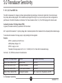
5.0 Transducer Sensitivity
5.1 X1, X2, X5 and DIV2 link
The LDX-D compensates for changes in primary signal amplitude by producing an internal error signal that is the ratio between
the primary and secondary signals. If the transducer output signal is too high or too, low errors may occur that can degrade the
performance of the LDX-D/transducer combination. For these transducers the X1, X2, X5 or DIV2 input gain link must be used.
Calculating transducer Full Range Output (FRO)
In general, transducer sensitivity is quoted as mV/V/mm where:
mV = output of the transducer V = primary voltage mm = mechanical position of the transducer from null (usually mid mechanical range).
To calculate the transducer full range output, simply multiply all three together.
Example:
GP911-1 sensitivity is 210 mV/V/mm
LDX-D primary voltage is 3 V
GP911-1 range is ±1 mm
Transducer full range output is 210 x 3 x 1 = 630 mV (0.63 V). It falls within the standard range.
Set the X2, X5, DIV2 link as shown in the table below:
Transducer Full Range Output
Comment
Input Gain Link setting
400 mV FRO to 2500 mV FRO
Standard range
Link ON X1
150 mV FRO to 400 mV FRO
Low output transducer
Link ON X2
150 mV FRO to 400 mV FRO
Very low output transducer
Link ON X5
2500 mV FRO to 5000 mV FRO
High output transducer
DIV2 - Links X1, X2, X5 parked (ie. all OFF)
5.0 Transducer Sensitivity
20
M-4346/1113