1
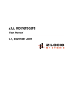
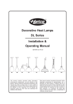
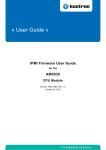
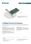
H-ACDC-70 Current
Sensor Board User Manual
Keith Youngblood, Youngblood Technologies <keith<at>youngbloodtech.com>
Bradley Whaley, Pedal Power Generator, LLC
H-ACDC-70 Current Sensor Board User Manual
by Keith Youngblood and Bradley Whaley
Revision v1.1
Revision v1.0
Revision History
2011-10-19
Changed contact information.
2010-11-24
Document release
kty
kty
Copyright © 2009-2011 Youngblood Technologies
Disclaimer Notice
We are not responsible for misuse of this equipment. These instructions are for reference purposes. The device must be operated by qualified
persons only. This device should not be used in life support devices or mission-critical applications. We reserve the right to change specifications,
dimensions and documentation of this device at any time without notice.
H-ACDC-70 Current Sensor Board
User Manual
Table of Contents
Preface ............................................................................................................................ vii
1. Introduction ................................................................................................................... 1
2. Safety Precautions ........................................................................................................... 2
3. Features and Specifications ............................................................................................... 3
Features and Information ............................................................................................. 3
Specifications ............................................................................................................. 3
Dimensions ............................................................................................................... 4
4. Using the Current Sensor ................................................................................................. 5
Connecting the Unit .................................................................................................... 5
Measuring Current ...................................................................................................... 7
5. Frequently Asked Questions ............................................................................................. 9
6. Troubleshooting and Support ........................................................................................... 10
iii
Document revision: v1.1
H-ACDC-70 Current Sensor Board
User Manual
List of Figures
3.1.
4.1.
4.2.
4.3.
Board Dimensions ........................................................................................................
Connecting the Power ...................................................................................................
Connecting Current Path ................................................................................................
Connecting the Output Voltage .......................................................................................
iv
4
5
6
7
Document revision: v1.1
H-ACDC-70 Current Sensor Board
User Manual
List of Tables
3.1. Current Sensor Specifications ......................................................................................... 3
v
Document revision: v1.1
H-ACDC-70 Current Sensor Board
User Manual
List of Equations
4.1. Sensor board calculation of sensed current from output voltage ............................................. 8
4.2. Determination of calibration value to use for sensor board ................................................... 8
vi
Document revision: v1.1
H-ACDC-70 Current Sensor Board
User Manual
Preface
Keith Youngblood
This manual is intended to assist one in the proper connection and operation of the H-ACDC-70 Current
Sensor Board. This manual should give the user enough information to utilize it successfully in her own
project.
This manual will not cover all potential uses of this sensor nor will it go into details on how to best utilize
the output of the sensor for any particular application. There will be some responsibility of the user to
determine the best way to use the sensor board for their application.
It will be assumed that the audience of this book will have basic knowledge of electricity, electrical safety
and Ohm's law. If the reader is not familiar with electronic circuits or comfortable in connecting this
hardware, they should seek a professional to assist in this work.
It is beyond the scope of this User Manual to describe specific programming functions, processes and
routines or to suggest any and all possibilities of using this sensor.
vii
Document revision: v1.1
H-ACDC-70 Current Sensor Board
User Manual
Chapter 1. Introduction
The H-ACDC-70 Current Sensor Board utilizes a linear output Hall effect transducer to allow the isolated
measurement of AC or DC electrical current by measuring the magnetic field surrounding a wire as a
current passes through the wire. The sensor board has an on-board voltage regulator to power the supplied
current transducer at a nominal potential.
The output of the sensor board is a voltage that is linearly proportional to the current present in the sensed
conductor at that moment (or around 3 microseconds ago to be exact). To increase current sensitivity (and
subsequently lower the current range) of the sensor, simply pass the sensed current path wire through the
sensor as many times as needed to increase the output sensitivity to the desired level.
When measuring purely AC currents, put a capacitor in series with the output of the sensor board. This
will decouple the DC offset voltage from the output signal leaving only an AC output that is proportional
to the AC current being sensed.
Use a voltmeter or data acquisition device to read the output of the current sensor board.
H-ACDC-70-K shown which includes a mounting kit
1
Document revision: v1.1
H-ACDC-70 Current Sensor Board
User Manual
Chapter 2. Safety Precautions
By installing and operating this current sensor board, the user is responsible for following all electrical
code and safety guidelines that are established in your country, state, county and/or city. Beware that high
current cables and wires can short out and cause liquid metal to form and cause personal injury, injury to
others and cause fires and other damage. Make sure all current paths have adequate over current protection
such as fuses and breakers.
By using this product, you agree that before operating your current sensor board, you will have a licensed
electrician look over your work to make sure that it is safe to operate.
Safety Checklist
• Use much caution when working with high voltage both AC or DC.
• Use fuses or circuit breakers to minimize damage caused by over-current conditions.
• Use insulated wire and insulated connections to prevent accidental contact with high voltages that may
be present in the circuit under test.
• Always power down the circuit when disconnecting and reconnecting the current path to prevent poor
contact whilst making and breaking connections. Poor contacts can cause large sparks, personal injury,
property damage and/or may cause a fire.
• Always be sure that the wire size used is capable of carrying the current expected. Over size the wire by
25% to be sure that it will nominally operate at 80% of the wires rating at the maximum expected current.
• Always use connectors and switches that are rated for the voltage and current that you are working with.
High voltages can degrade materials and cause them to fail if they are not rated for the votage they are
exposed to. Also, connectors and switches that are not properly rated for current can be damaged and
cause personal injury, property damage and/or cause a fire.
2
Document revision: v1.1
H-ACDC-70 Current Sensor Board
User Manual
Chapter 3. Features and Specifications
The following define the basic features and specifications for the sensor used in this product.
Features and Information
Sensor Features
Typical Applications
•
•
•
•
•
•
•
•
•
•
•
•
•
•
•
•
•
Linear output
AC or DC current sensing
Through-hole design
Fast response time
Output voltage isolation from input
Minimum energy dissipation
Maximum current limited only by conductor
size
• Adjustable performance and built-in temperature compensation assures reliable operation
• Accurate, low cost sensing
• Housing: PBT polyester
Variable speed drives
Overcurrent protection
Ground fault detectors
Current feedback control systems
Robotics
UPS and telecommunication power supplies
Welding power supplies
Automotive - Battery management systems
Wattmeters
Solar, wind, hydroelectric and other power
generation/usage monitoring
Specifications
Table 3.1. Current Sensor Specifications
Product Type
Inductive Analog Current Sensor
Sensed Current Type
Sensed Current Range
AC or DC
a
±72 Amps ÷ N
Output Type
Sensitivity
Voltage
a
32.7 mV × N ±3.0 mV × N
Supply Voltage
11.0 Vdc to 30.0 Vdc
Supply Current
Output Offset Voltage (Voffset)
13mA nominally, 20mA Max
b
4 Volts ±2 %
Max. Output Current
10 mA (Sink or Source)
Response Time
3 µs
Operating Temperature
-25 °C to 85 °C [-13 °F to 185 °F]
Storage Temperature
-40 °C to 100°C [-40 °F to 212 °F]
a
N denotes number of turns the wire is passed through the sensor element.
When monitoring purely AC current with zero DC component, a capacitor can be inserted in series with the output of the current
sensor. The capacitor will block out the effect of the temperature variation of the offset voltage which increases the accuracy of
the device.
b
3
Document revision: v1.1
Dimensions
H-ACDC-70 Current Sensor Board
User Manual
Dimensions
Figure 3.1. Board Dimensions
4
Document revision: v1.1
H-ACDC-70 Current Sensor Board
User Manual
Chapter 4. Using the Current Sensor
Usage overview paragraph goes here
Connecting the Unit
Use the following steps to connect the H-ACDC-70 series Current Sensor Boards:
1.
Mounting the sensor board unit
It is best to mount the current sensor board securely during operation in order to prevent any unwanted
short circuits or other electrical hazards. Think about the mounting place to be sure it will not cause
damage to any equipment, cause an obstruction or safety hazard.
For best results, try to place the sensor element where it will be able to have the current path (the wire
being measured) pass through the eye of the hall transducer without going out-of-the-way to do so.
There are mounting holes for #6 (4mm) screws in each corner of the sensor board and the HACDC-70-K mounting flange. Use plastic or metal standoffs with the screws to prevent the backside
of the sensor board from coming into contact with objects that can cause short circuits.
2.
Connecting Power
The current sensor board requires DC power to operate. A 2.5mm power jack is provided to make
this power connection. Connect to this jack a plug with 11 to 30 volts DC with the center positive.
The sensor board is equiped with a reverse-voltage protection diode so that a reverse power connection
will not cause damage to the on-board regulator IC or Hall transducer. Note, a reverse voltage will
not power the sensor board.
Figure 4.1. Connecting the Power
3.
Installing Measured Current Path
In order to measure current in an application, the current must pass though the sensor element at least
once. To do this, power down the circuit under test and pass the wire that will pass the current to be
measured through the hole in the sensor element. Reconnect the wire to the circuit under test and re-
5
Document revision: v1.1
Connecting the Unit
H-ACDC-70 Current Sensor Board
User Manual
apply the power. current may flow though the sensor whether or not the sensor board is powered up or
not. The sensor will not affect the circuit under test regardless if it is powered up or not. It will mearly
sense the presence and magnitude of current when it is powered by outputting a voltage that is linearly
proportional to the current present in the current path directed through the sensor transducer element.
Be sure to use a conductor that is of an appropriate size for the current expected. Failure to do so can
result in surprising effects and possible personal injury and property damage. See Safety Precautions
chapter above.
Figure 4.2. Connecting Current Path
4.
Connecting the Output
Connect the screw terminals of the output to your voltmeter or data acquisition system as shown
below. Make note of the positive and negative output terminal polarity to ensure proper output value
and polarity. A reversal of this connection may cause an inverted reading indicating a measured
current flow of the opposite polarity.
Keep in mind that the negative terminal of the output (ground connection or GND) is common with
and directly connected to the negative terminal of the power connector of the current sensor board.
In rare circumstances, this can cause problems with data acquisition systems or other connections by
forming a ground-loop or an unintended short-circuit in a system.
6
Document revision: v1.1
Measuring Current
H-ACDC-70 Current Sensor Board
User Manual
Figure 4.3. Connecting the Output Voltage
Measuring Current
Describe that there are many ways to read this board's output, including...
Using a multimeter
You can use a voltmeter to read the output of the sensor board. To do so, simply connect your voltmeter or
multimeter to the current sensor output terminals. If using a multimeter, be sure to use the voltage setting
on the selection dial. If you plan to read AC currents use the AC voltage setting and use DC voltage setting
to read DC currents that pass through the sensor board.
The voltage that you read with this method will be linearly proportional to the current present in the
conductor being sensed. This voltage will be nominally 32.7 millivolts per amp measured. To convert the
voltage read to a value representing measured current, divide the voltage reading you get by 0.0327. This
value is nominal and can vary from sensor to sensor by ±3 millivolts. See the calibration section below
for more details.
You can manually use these reading in conjunction with spreadsheet or graphing software to produce
histograms or other representations of the data read.
Using a DAQ
By using a data acquisistion device, the sensor may be read in a continuous and automatic fashion thereby
allowing for the data to be graphed or otherwise processed using a computer. Calibration parameters can
be determined and programmed into the data acquisition software to allow more accurate reading to be
easily performed. This is by far the most recommended method for reading the output of the sensor.
Using a microcontroller/ADC
You may also read the output of the current sensor using an analog to digital converter IC or a microcontroller with a built-in analog to digital converter. Many of the analog to digital converters available will
7
Document revision: v1.1
Calibration
H-ACDC-70 Current Sensor Board
User Manual
have a different voltage range than the current sensor outputs. This may be accommodated by lowering the
output using a passive, resistive voltage-divider circuit or by using an active operational amplifier circuit
to produce the proper gain for your application.
You will need to calibrate your readings in software/firmware to make adjustments to the gain stages that
are introduced. See the calibration section below for more details.
Calibration
Calibrating the sensor can be performed a number of ways depending on how you are reading the values
and what other circuitry you may have included.
The default output of the sensor board can be calculated as follows:
Equation 4.1. Sensor board calculation of sensed current from output voltage
Where N is the number of times the sensed current path wire is passed though the sensor element, Voffset
is nominally 4.0 VDC and Vout is the voltage measured on the output terminals of the sensor board.
The 32.7mV may vary by ±3 volts. This value may need to be adjusted in your calibration procedure to
obtain the most accurate readings. To determine the appropriate value to use, connect the sensor board to a
test circuit and use a known accurate ammeter or multimeter to measure the current in the test circuit while
also measuring the output voltage from the sensor. Use the following equation to compute the calibration
value for your sensor board:
Equation 4.2. Determination of calibration value to use for sensor board
Where Vcalib is the derived calibration value, N is the number of times the test circuit current path wire
is passed through the sensor element, Voffset is the offset voltage of the sensor board at quiescence
(nominally, 4.0 volts), Isense is the known current in the test circuit and Vout is the output voltage
measured while the test current was present in the test circuit current path wire at the time the known
current was present.
To use this calibration value, substitute the value calulated with the 32.7mV value used in the above
equation 4.1.
For the utmost accuracy, the value of Voffset may also be modified to reflect the actual Voffset
measured at quiescence as Voffset may vary slightly from sensor board to sensor board.
8
Document revision: v1.1
H-ACDC-70 Current Sensor Board
User Manual
Chapter 5. Frequently Asked Questions
Q:
When measuring AC current, does this sensor put out an AC or DC signal?
A:
It puts out an AC signal.
Q:
If I am using this with a 24 Volt battery application can I just hook the operating power up to the
battery?
A:
Yes, this device can take a 12 to 30 Volts DC power supply to excite the transducer using the black
2.5mm positive center.
Q:
What is the absolute maximum current this device can measure?
A:
The specifications rate this sensor for 72 Amps. I don't have a power supply big enough to test this
device in that range.
Q:
How can use this sensor for low current situations less then one amp?
A:
All you have to do is loop the wire through the sensor multiple times until you get the signal strength
you need. Then divide the measurement you are getting by how many loops you have put through
the sensor. For example, if you loop your current carrying wire through the sensor 10 times, and you
get a measurement of 4.032 and your sensor measures 4.0 when no current is flowing through the
transducer, then the approximate current calculation would be :
((4.032 - 4.0)/ 0.033) / 10 = 0.096 Amps or 96mA
Also, see the calibration section above for more details.
9
Document revision: v1.1
H-ACDC-70 Current Sensor Board
User Manual
Chapter 6. Troubleshooting and
Support
If you require more information or assistance with the setup or usage of this device, please visit our website
at http://measure-current.com There you will find more documentation regarding the operation of this
sensor board as well as other great ideas.
If you need to contact our support team: write keith<at>youngbloodtech.com or call 360-545-3869 (MF 8AM to 4PM Pacific Time).
10
Document revision: v1.1