1
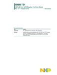
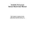
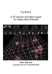
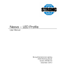
ZIO, Motherboard
User Manual
0.1, November 2009
ZIO, Motherboard User Manual
Rev. 0.1
ZIO, Motherboard User Manual
Rev. 0.1
Table of Contents
1. Introduction ............................................................................................................................ 1
1. Philosophy ..................................................................................................................... 1
2. Product Features ............................................................................................................ 1
2. Connecting to ZIO .................................................................................................................. 2
1. GPIO Port ...................................................................................................................... 2
2. I2C Port ......................................................................................................................... 3
3. Sensor Port ................................................................................................................... 4
4. PWM Port ...................................................................................................................... 5
3. ZIO Recipies .......................................................................................................................... 7
1. GPIO Port ...................................................................................................................... 7
2. I2C Port ......................................................................................................................... 9
3. Sensor Port .................................................................................................................. 10
4. PWM Port .................................................................................................................... 13
4. ZIO Control Panel ................................................................................................................ 16
1. Controlling GPIO Outputs ............................................................................................. 16
2. Reading GPIO Inputs ................................................................................................... 16
3. Reading Sensor Inputs ................................................................................................. 16
4. Controlling PWM Outputs .............................................................................................. 16
5. Controlling I2C Devices ................................................................................................ 16
A. Port Pin Mapping ................................................................................................................. 18
Zilogic Systems
Page iii
ZIO, Motherboard User Manual
Rev. 0.1
Chapter 1. Introduction
1. Philosophy
• Move development from micro-controllers to PC
• Use high level languages like Python and Java.
• Extend the IO capabilities of the PC.
• Rapid prototype development.
2. Product Features
• Connects to PC through USB
• Interfaces
– I2C
– Sensor Input
– GPIO
– PWM Output
• Host-side API for programming the ports
• APIs available for Java and Python
• API documentation for easy reference
• Port interfacing guidelines for common scenarios
• GUI based Control Panel to explore the board
• On-field firmware upgrade through USB
Figure 1.1. Block Diagram
Zilogic Systems
Page 1
ZIO, Motherboard User Manual
Rev. 0.1
Chapter 2. Connecting to ZIO
In this chapter we will describe the connector used for the ZIO ports and the pins found on each of the
ports. The ZIO has 4 different types of ports.
1. GPIO Port
2. I2C Port
3. Sensor Port (Marked as AIN on the ZIO)
4. PWM Port
All the ports are available through RJ12 jacks. The RJ12 is similar to RJ11, but has six pins. The RJ12
jack pins and pin numbering are shown in the following diagram.
Figure 2.1. RJ12 Jack
1. GPIO Port
The ZIO has two GPIO ports, marked as GPIO-0 and GPIO-1. The signals on a GPIO port are shown
in the following table.
Table 2.1. GPIO Port Signals
Pin No.
Signal
1
+5V Power
2
Output 0
3
Output 1
4
Input 0
5
Input 1
6
GND
+5V Power (Pin 1)
This is the power supply for the external device. The supply has a total
current limit of 200mA.
Output 0, 1 (Pin 2, 3)
These are digital output signals. The signal is a 5V logic signal, but
the output can drive a 5V device or 3.3V device with 5V tolerance.
The output signal has a series resistor of 180 ohm (FIXME), to protect
against accidental shorting to GND.
Input 0, 1 (Pin 2, 3)
These are digital input signals. The signal is a 5V logic signal. The signal
is pulled up to 5V, through a 10K resistor.
GND (Pin 6)
This is the ground signal. All other signals are referenced to the this
signal.
Zilogic Systems
Page 2
ZIO, Motherboard User Manual
Rev. 0.1
Figure 2.2. GPIO Port
2. I2C Port
The ZIO has three I2C ports, marked as I2C-0, I2C-1 and I2C-2. The signals on a I2C port are shown
in the following table.
Table 2.2. Sensor Port Signals
Pin No.
Signal
1
+5V Power
2
SCL
3
SDA
4
Reserved
5
Interrupt
6
GND
+5V Power (Pin 1)
This is the power supply for the external devices. The supply has a total
current limit of 200mA.
SCL, SDA (Pin 2, 3)
These are I2C bus signals, and can be used to connect I2C devices.
Any 5V tolerant I2C device, can be connected to the bus.
Interrupt (Pin 5)
This is a digital input signal. This is a shared signal for all I2C devices
and should be driven by open collector outputs. The signal is pulled up
to 5V, through a 10K resistor.
GND (Pin 6)
This is the ground signal. All other signals are referenced to this signal.
Zilogic Systems
Page 3
ZIO, Motherboard User Manual
Rev. 0.1
Figure 2.3. I2C Port
3. Sensor Port
The ZIO has four sensor ports, marked as AIN-0, AIN-1, AIN-2 and AIN-3. The signals on a sensor
port are shown in the following table.
Table 2.3. Sensor Port Signals
Pin No.
Signal
1
+5V Power
2
SCL
3
SDA
4
Sensor 0
5
Sensor 1
6
GND
+5V Power (Pin 1)
This is the power supply for the external sensors. The supply has a total
current limit of 200mA.
SCL, SDA (Pin 2, 3)
These are I2C bus signals, and can be used to connect I2C devices.
Any 5V tolerant I2C device, can be connected to the bus.
Sensor 0, 1 (Pin 4, 5)
These are analog input signals. The signals are connected to a 10-bit
ADC. The input signal range is 0 to 3V. The input is translated to a value
in the range 0 to 1023, by the ADC. The pins are connected to a 3V
reference through 10K pull up resistors.
GND (Pin 6)
This is the ground signal. All other signals are referenced to this signal.
Zilogic Systems
Page 4
ZIO, Motherboard User Manual
Rev. 0.1
Figure 2.4. Sensor Port
4. PWM Port
The ZIO has one PWM port, marked as PWM-0. The signals on a PWM port are shown in the following
table.
Table 2.4. Sensor Port Signals
Pin No.
Signal
1
+5V Power
2
PWM 0
3
PWM 1
4
Phase A
5
Phase B
6
GND
+5V Power (Pin 1)
This is the power supply for the external sensors. The supply has a total
current limit of 200mA.
PWM 0, 1 (Pin 2, 3)
These are PWM output signals. The PWM signal when active produces
a stream of pulses whose width can be controlled through software. An
important parameter of a PWM signal is the duty cycle. The duty cycle
is defined as the ratio between the pulse duration and pulse period of
a rectangular waveform.
The PWM signal can be used to control the power delivered to a load, by
controlling the duty cycle of the PWM signal. PWM signals are generally
used for Motor speed control, LED brightness control, power supplies
and wave form generation.
The PWM signal is a CMOS/TTL output. The signal has a series resistor
of 180 ohm (FIXME), to protect against accidental shorting to GND.
Zilogic Systems
Page 5
ZIO, Motherboard User Manual
Rev. 0.1
Figure 2.5. PWM signals with various pulse widths
Phase A, B (Pin 4, 5)
These are digital input signals, to be driven by the two outputs of a
quadrature encoder. This can be used to determine the speed and
direction of rotation of the shaft to which encoder is attached. This
is generally used to determine the speed and direction of the motor
controlled by the PWM signal.
The Phase signal is a CMOS/TTL input. The signal is pulled up to 5V,
through a 10K resistor.
GND (Pin 6)
This is the ground signal. All other signals are referenced to this signal.
Figure 2.6. PWM Port
Zilogic Systems
Page 6
ZIO, Motherboard User Manual
Rev. 0.1
Chapter 3. ZIO Recipies
1. GPIO Port
Connecting LEDs. Connect the anode of the LED to an Output signal, and the cathode to GND.
The built-in series resistor is sufficient to limit the current.
Connecting series of LEDs. Since the Output signal can not provide sufficient power for more than
one LED, and external power source is to be used. And the power supply can be controlled using a
MOSFET switch.
The circuit diagram for connecting a series of LEDs is shown above. The following formula can be used
to calculate the resistance for the current limiting resistor. (The voltage drop across the MOSFET is
considered to be negligible.)
R = (Vcc - NVd) / Id
Where,
Vd
Voltage Drop Across LED
N
No. of LEDs
Id
Current for the required brightness
Vcc
LED supply voltage
R
Current Limiting Resistor
As an example, for the following parameters,
• Vcc = 12V
• Id = 11mA
• N=4
the calulated current limiting resistance is 470 ohms.
Connecting relays. Relays are used to control a high-voltage/high-currect circuit with a low-voltage/
low-current signal. A relay can be connected to the ZIO through a MOSFET as shown in the following
circuit diagram.
Zilogic Systems
Page 7
ZIO, Motherboard User Manual
Rev. 0.1
Isolating outputs using opto-coupler. There are situations in which signals from one subsystem
need to be electrically isolated from another subsystem in an electrical equipment. For example, a
microcontroller operating at 5V, controls the power to a load operating at 230V AC. In such situations,
the microcontroller needs to be electrically isolated from the high voltage section, using a opto-coupler.
Note that, though relays can also be used for this purpose, they are generally bulky, slow, unreliable,
and power hungry.
Connecting to CMOS/TTL inputs. CMOS/TTL inputs can be directly connected to the Output
signal. An example of shift register connected to the Output signals is shown in the following circuit
diagram.
Connecting Switches. Switches can be directly connected between the Input and GND. When the
switch is pressed the Input signal will be low, and when the switch is released the Input signal will
be become high due to the built-in in pull-up resistor.
Detecting External Voltage. Any external voltage input can be connected to the ZIO Input signal
through a MOSFET or a BJT. An example circuit using a MOSFET is shown below.
Zilogic Systems
Page 8
ZIO, Motherboard User Manual
Rev. 0.1
If the input voltage (Vs) is greater than the threshold voltage of the MOSFET, the Input signal will be
low, or else it will be high.
An example circuit using a BJT is shown below.
If the input current (Is) is greater than (It = 0.5mA / hFE), the Input signal will be low, or else it will
be high. For all practical purposes, a (It = 1mA) input current is sufficient to make the Input signal
go low. The base resistance (Rb) has to be chosen to make the Input signal low, when the required
input voltage is driven.
Rb = (Vs - Vbe) / It
Connecting an Analog Comparator. An analog comparator can be used to identify if the input
voltage is larger than a specified reference voltage. Any operational amplifier can be used as a
comparator, but a dedicated comparators like LM339 which provide open collector CMOS/TTL outputs
are suitable for interfacing with logic circuits. An example circuit is shown in the following diagram.
Isolating inputs using opto-coupler. As in the case of outputs, inputs can also be electrically isolated
using opto-couplers.
2. I2C Port
Connecting 5V I2C devices. Since the I2C signal are pulled up to 5V, 5V I2C devices can be directly
connected to the I2C port.
Zilogic Systems
Page 9
ZIO, Motherboard User Manual
Rev. 0.1
Connecting 3.3V I2C devices with 5V tolerance. Any 3.3V I2C device with 5V tolerance can be
directly connected to the I2C port. The device can be powered from an external 3.3V supply, or the 3.3V
supply can be generated from the +5V Power using a regulator. An example ciruit with the commonly
available LM1117-3.3 regulator is shown below.
IO Expander. Additional digital inputs and outputs, if required, can be obtained using a I2C IO
expander. The PCA8574 provides 8 digitial I/O lines, and PCA8578 provides 16 digital I/O lines. An
example circuit using the PCA8574, with I2C device address set to 0x20, is shown below.
3. Sensor Port
3.1. Resistive Sensors
Connecting a Potentiometer. The position of potentiometer can be sensed by connecting the
potentiometer to the sensor input as shown in the figure below. When the center pin 2 of the
potentiometer is moved from pin 1 to pin 3, the raw value varies from 0 to Nmax. Where Nmax is given
by the following formula.
Nmax = (0xFFFF x Rmax) / (Rmax + 10K)
Here,
• Rmax is the maximum resistance of the potentiometer
Zilogic Systems
Page 10
ZIO, Motherboard User Manual
Rev. 0.1
• 10K is the internal pull up resistor on the Sensor signal. For more details refer Section 3, “Sensor
Port”.
For a 10K potentiometer, Nmax = (0xFFFF x 10K) / (10K + 10K) = 0x7FFF
Connecting a Resistive Sensor. Sensors whose resistance varies with the parameter being
measured are called resistive sensors. Examples of resistive sensors are Light Dependent Resistor
(LDR), thermistor, etc. These sensors can be directly connected between the Sensor signal and GND.
As the parameter being measured varies, the resistance varies accordingly, and the raw value (N)
produced is given by the following formula.
N = (0xFFFF x R) / (R + 10K)
Here,
• R is the resistance of the sensor
• 10K is the internal pull up resistor on the Sensor signal. For more details refer Section 3, “Sensor
Port”.
An example circuit, using the LDR, is shown below.
3.2. Voltage Sensors
Voltage measurement, -3V to +3V. Though the ADC input range is 0 to 3V, it is possible to measure
voltages between -3V and +3V using a simple circuit. The circuit diagram is shown in the figure below.
To better understand the operation of the circuit, the circuit is shown with the internal pull-up resistor
on the Sensor signal, in the following diagram.
Zilogic Systems
Page 11
ZIO, Motherboard User Manual
Rev. 0.1
Using superposition, the voltage at Sensor 0 is given by the following formula.
Voltage at Sensor 0 = 1.5V + Vi / 2
As Vi decreases from 3V to -3V, the voltage at the Sensor 0 decreases linearly from 3V to 0V, and
the raw value from 0xFFFF to 0.
Vi (V)
Voltage at Sensor 0 (V)
Raw Value
3
3
0xFFFF
0
1.5
0x7FFF
-3
0
0
Voltage measurement, -15V to +15V. The following circuit can be used to measure voltages in the
range -15V to +15V. The input voltages and the corresponding raw values is shown in the table below.
Vi (V)
Voltage at Sensor 0 (V)
Raw Value
15
3.0
0xFFFF
0
1.5
0x7FFF
-15
0.0
0
3.3. Non-resistive Sensors
Transistor Buffer. Non-resistive sensors usually generate a voltage signal that varies with the
parameter being measured. Such sensors cannot be directly connected to the Sensor N signal, due
the signal being pulled-up to 3V using a 10K resistor. A transistor buffer can be used to overcome this
problem. The transistor isolates the sensor from the pull-up. A transistor buffer circuit is shown below.
Zilogic Systems
Page 12
ZIO, Motherboard User Manual
Rev. 0.1
This is a PNP emitter follower, where the emitter voltage is almost equal to the base voltage. For a Vi
range of 0 to 4.4V, the voltage at Sensor 0 is (Vi + 0.6). To compensate for the added 0.6V, subtract
0.6 to the obtained voltage.
Temperature Sensor. The LM35 is an example of an non-resistive sensor. The LM35 produces a
voltage that is propotional to the temperature. The voltage output by the LM35, increases by 10mV for
o
o
every degree Celcius rise in temperature. As the temperature changes from 2 C to 150 C, the voltage
rises from 0V to 1.5V. The LM35 can be connected to the Sensor port using the transistor buffer and
is shown in the following circuit.
4. PWM Port
LED Brightness Control. An LED can be connected between the PWM N signal and GND as shown
in the following diagram. When the duty cycle is varied the LED brightness varies accordingly.
One Bit DAC. An analog output can be generated from the PWM signal, using a low pass filter circuit.
The low pass filter circuit with an op-amp buffer is shown in the following diagram.
If the analog output has a frequency of F, the PWM frequency should be much higher than F. The values
of R and C are given by the following formula.
RC = 1 / (2
F)
For an output frequency of 1kHz, choosing R = 4kohm, C = 0.04uF.
DC Motor Control. A DC motor's speed and direction of rotation can be controlled using the PWM
port. The DC motor has to be interfaced through a circuit called the H-Bridge. A simple H-Bridge
constructed using switches is shown in the following diagram. By controlling, the switches the motor
can be made to rotate forward, reverse, brake, and free run. The various switch states and their effect
on the motor is shown in the following table.
Zilogic Systems
Page 13
ZIO, Motherboard User Manual
Rev. 0.1
S1
S2
S3
S4
Function
0
0
0
0
Free-run
0
1
1
0
Reverse
1
0
0
1
Forward
0
1
0
1
Brake
1
0
1
0
Brake
Forward
The current to flows in one direction through the motor.
Reverse
The current flows in the opposite direction through the motor.
Brake
Applying same voltage to both the terminals, counters the back EMF produced by
the motor, and causes it to come to a sudden stop.
Free-run
Power is cut-off from the motor, and the motor free-runs and eventually stops.
To control the motor through digital signals, the switches are replaced by transistors / MOSFETs. Driver
ICs like the L298, that implement the H-Bridge can also be used for motor control applications. The
block diagram of one half of a L298 is shown in the following diagram.
Zilogic Systems
Page 14
ZIO, Motherboard User Manual
Rev. 0.1
By controlling the inputs, various functions can be selected, as shown in the table below.
In1
In2
Function
0
0
Brake
0
1
Reverse
1
0
Forward
1
1
Brake
When in Forward state or Reverse state, the speed of the motor can be controlled by driving the inputs
with a PWM signal
In1 (Duty Cyle)
In2 (Duty Cycle)
Function
0%
0%
Brake
100%
100%
Brake
0%
100%
Reverse, full speed
100%
0%
Forward, full speed
0%
X%
Reverse, speed propotional to duty cycle
X%
0%
Forward, speed propotional to duty cycle
A circuit for interfacing a DC motor to the PWM port using the L298, is shown in the following diagram.
Zilogic Systems
Page 15
ZIO, Motherboard User Manual
Rev. 0.1
Chapter 4. ZIO Control Panel
The ZIO Control Panel is a GUI application that allows most features of ZIO to be tested without writing
code.
Figure 4.1. Control Panel Screenshot
1. Controlling GPIO Outputs
The GPIO outputs can be controlled by toggling the check box on the Digital Out panel.
2. Reading GPIO Inputs
The GPIO inputs can be read by inspecting the check box on the Digital In panel.
3. Reading Sensor Inputs
The Sensor inputs can be read by inspecting the progress bar on the Sensor panel.
4. Controlling PWM Outputs
PWM signals can generated using the controls in the PWM panel,
1. Select the PWM channels, by toggling the checkboxes.
2. Set the PWM frequency, in the frequency slider.
3. Set the PWM duty cycle, in the duty cycle slider.
4. Click Start to start generating PWM signal.
5. Click Stop to stop generating PWM signal.
5. Controlling I2C Devices
I2C devices can be accessed using the controls in I2C panel. To list devices present on the bus,
Zilogic Systems
Page 16
ZIO, Motherboard User Manual
Rev. 0.1
1. Click on the Scan button.
2. Address of devices present is displayed on the list box.
To write to a device,
1. Select the device address.
2. Enter the data bytes to be written in hex, separated by commas, in the Write text box.
3. Click on the Write button.
To read from a device,
1. Select the device address.
2. Select the no. of bytes to read.
3. Click on the Read button.
Zilogic Systems
Page 17
ZIO, Motherboard User Manual
Rev. 0.1
Appendix A. Port Pin Mapping
The API deals with subsystems in the board called modules. The modules available in the API are.
1. GPIO
2. I2C
3. Sensor
4. PWM
Each module controls a set of pins. These pins are terminated in the pins of various ports. An example
with GPIO module is shown in the following diagram.
The API always deals with modules and its pins. So to control a pin on a particular port, it is required
to know which pin on the module it is mapped to.
Table A.1. Port GPIO-0
Signal
Module
Pin
Output-0
GPIO
0
Output-1
GPIO
1
Input-0
GPIO
0
Input-1
GPIO
1
Table A.2. Port GPIO-1
Signal
Module
Pin
Output-0
GPIO
2
Output-1
GPIO
3
Input-0
GPIO
2
Input-1
GPIO
3
Table A.3. Port I2C-0
Signal
Module
Pin
SDA
I2C
-
SCL
I2C
-
Interrupt
GPIO
4
Zilogic Systems
Page 18
ZIO, Motherboard User Manual
Rev. 0.1
Table A.4. Port I2C-1
Signal
Module
Pin
SDA
I2C
-
SCL
I2C
-
Interrupt
GPIO
4
Table A.5. Port I2C-2
Signal
Module
Pin
SDA
I2C
-
SCL
I2C
-
Interrupt
GPIO
4
Table A.6. Port AIN-0
Signal
Module
Pin
SDA
I2C
-
SCL
I2C
-
Sensor-0
Sensor
0
Sensor-1
Sensor
1
Table A.7. Port AIN-1
Signal
Module
Pin
SDA
I2C
-
SCL
I2C
-
Sensor-0
Sensor
2
Sensor-1
Sensor
3
Table A.8. Port AIN-2
Signal
Module
Pin
SDA
I2C
-
SCL
I2C
-
Sensor-0
Sensor
4
Sensor-1
Sensor
5
Table A.9. Port AIN-3
Signal
Module
Pin
SDA
I2C
-
SCL
I2C
-
Sensor-0
Sensor
6
Sensor-1
Sensor
7
Table A.10. Port PWM-0
Signal
Module
Pin
PWM 0
PWM
0
PWM 1
PWM
1
Zilogic Systems
Page 19