1
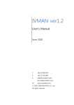
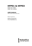
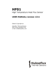
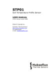
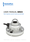
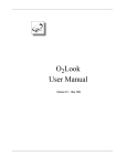
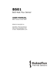
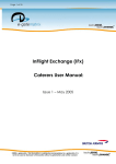
HF03 / LI19 PORTABLE HEAT FLUX SENSOR, WITH READ-OUT UNIT USER MANUAL HF03 / LI19 manual v1215 Edited & Copyright by: Hukseflux Thermal Sensors http://www.hukseflux.com e-mail: [email protected] Hukseflux Thermal Sensors Warnings and safety issues: HF03 / LI19 is NOT certified for EEx environments. HF03 is designed for fluxes up to 10 kW/m2. LI19 is suitable for normal exposure only; up to 2 kW/m2. Make sure that LI19 is switched off whenever it is not used. Make sure to have spare batteries available whenever using LI19. Make sure to have read the LI19 manual before using LI19. LI19 software is not supplied with the instrument. It should be downloaded from http://www.leiderdorpinstruments.nl HF03 / LI19 manual v1215 page 2/16 Hukseflux Thermal Sensors Contents 1 2 3 4 5 6 7 7.1 7.2 List of symbols Introduction Specifications of HF03 / LI19 General Theory Short user guide Putting HF03 / LI19 into use Maintenance of HF03 Electrical connection of HF03 Appendices Appendix on trouble shooting Allowable levels HF03 / LI19 manual v1215 4 5 7 8 9 12 13 14 15 15 16 page 3/16 Hukseflux Thermal Sensors List of symbols Heat flux Voltage output HF03 sensitivity HF03 / LI19 manual v1215 W m-2 Vsen V Esen V/Wm-2 page 4/16 Hukseflux Thermal Sensors Introduction The HF03 is a heat flux sensor that can be used in mobile applications. It is combined with LI19, a high accuracy hand-held read-out unit that can be used both for mobile measurements and as an amplifier directly connected to a PC. The combination HF03 / LI19 is typically used to study heat flux levels around flares and fires, and to calibrate flare radiation monitors / flare heat flux sensors. The HF03 is a heat flux sensor of the type that is commonly used in fire testing. The HF03 housing and sensor are designed to be suitable for short (10 minute) observation of high flux environments (up to 10 kW/m2). LI19 is suitable for normal exposure only; up to 2 kW/m2. LI19 is used to display the measured flux level; for attaining that, the sensitivity of HF03 is entered into the LI19, by programming it using a PC. USB connection is part of the delivery. Software should be downloaded via internet (this is to ensure that the latest version is applied). The applied site is: http://www.leiderdorpinstruments.nl. The LI19 is battery powered, using 2 AA-type batteries. These are included in the delivery. Batteries allow 50 days of operation. HF03 / LI19 is not rated for EEx environments, nevertheless it is admitted in many cases, because the instrument operates on 3VDC only. HF03 / LI19 manual v1215 page 5/16 Hukseflux Thermal Sensors 1 2 8 5 0 .0 3 k W /m 2 4 L I-1 9 9 6 5 10 11 Figure 0.1 LI19 connected to HF03. Heat flux sensor surface (11), metal heat sink (10), plastic grip (9), polyurethane cable (7). Operation: 1 switch on LI19, connect HF03 2 connect LI19 to PC, using USB connection box and LI19 software 3 check sensor settings 4 disconnect from PC 5 optional: mark settings on LI19 6 remove HF03 cap 7 start measurement 8 switch off LI19 Delivery: HF03 / LI19 / 2 spare batteries / Transport casing / USB connection box / cap HF03. Software should be downloaded from http://www.leiderdorpinstruments.nl HF03 / LI19 manual v1215 page 6/16 Hukseflux Thermal Sensors 1 Specifications of HF03 / LI19 The HF03 is a heat flux sensor that can be used in mobile applications. It is combined with LI19, a high accuracy hand-held read-out unit that can be used both for mobile measurements and as an amplifier directly connected to a PC. It is supplied with a transport case. HF03 / LI19 GENERAL SPECIFICATIONS Heat flux range for up to 10 kW/m2 HF03: Exposure time for 10 minutes (max) HF03: Heat flux range for up to 2 kW/m2 LI19: Exposure time for indefinite LI19: Cable length: 5m response time 1 s (nominal value) Temperature range -30 to +80 °C A/D resolution: 1 or 10 µV or 0.1 kW/m2 Software To be downloaded from http://www.leiderdorpinstruments.nl Display functions: actual values Weight: power supply: Transport casing Sensor sensitivity LI19 plus HF03: 1 kg Including transport casing: 2.5 kg Transport casing dimensions: 30 x 40 x 12 cm approximately Two AA-Type batteries, Alkaline supplied with the instrument 0.1 mV/kW/m2 At 1000 W/m2: 100 μV At 100 kW/m2: 10 mV Around 180 degrees Removable cap Sensor field of view Sensor protection CALIBRATION Calibration NIST traceability Recalibration interval Every 2 years Table 1.1 List of HF03 / LI19 specifications HF03 / LI19 manual v1215 page 7/16 Hukseflux Thermal Sensors 2 General Theory The HF03’s main component is a heat flux sensor. The sensor is located under the black surface on the front of the HF03. It is mounted on a metal heat sink, which is in turn protected by a plastic housing. The heat flux sensor generates a small voltage signal that is a linear function of the incoming radiant and convective heat flux. Using HF03 is easy. For readout, one only needs an accurate voltmeter that works in the millivolt range. To convert the measured voltage Vsen to a heat flux , the voltage must be divided by the sensitivity Esen, a constant that is supplied with each individual sensor. = Vsen / Esen 2.1 The sensitivity of HF03 is supplied with each individual instrument, and can be found on its calibration certificate. HF03 is read-out by LI19, which essentially is a voltmeter in which a calibration factor can be entered, to show watt per meter square. Expected accuracy: The expected accuracy of a measurement with HF03 depends on many factors, but most of all on: 1 the intensity of the radiation 2 wind effects HF03 is calibrated with a radiant source under conditions of “natural convection” i.e. no wind. The wind can play a large role in determining the end result of the heat flux measurement, and also in discrepancies between measurement results of one sensor type and another because surface temperatures on different sensors will deviate from each other. The quantification of this effect is strongly dependent on the circumstances. However, deviations of up to 20% have been reported for different sensor designs, although these were calibrated under the same conditions. HF03 / LI19 manual v1215 page 8/16 Hukseflux Thermal Sensors 3 Short user guide 0 unpack 0.1 in case this is not done before: download software from http://www.leiderdorpinstruments.nl (products – LI19 – more – downloads) 0.2 in case this was not done before: take the plastic units strip and cut off the units that are required. The small strip can be placed on the LI19 front below that display. 1 switch on LI19, connect HF03 2 connect LI19 to PC, using USB connection box and LI19 software 3 check sensor settings 4 disconnect from PC 5 optional: mark settings on LI19 6 remove HF03 cap 7 start measurement 8 switch off LI19 Figure 3.1 LI19 screen at startup. Typically the front of the LI19 should have the sensor information copied (possibly on a sticker). HF03 / LI19 manual v1215 page 9/16 Hukseflux Thermal Sensors Figure 3.2 LI19 connected to the USB connection box. Installation of the LI19 program will typically be done automatically by the windows installer. In case older program versions are present, one might need to uninstall earlier versions. If the LI19 program is opened, the LI19 must be connected, using the USB connection box. The control untilities will automatically recognise the LI19, and the window as shown in figure 3.3 will open, giving the message that the unit is connected. HF03 / LI19 manual v1215 page 10/16 Hukseflux Thermal Sensors Figure 3.3. LI19 software screen. Press sensor settings: Figure 3.4 LI19 sensor settings screen. Press Select Sensor, and select HF03. Select the appropriate calibration figure for the HF03 that is used. This will be around 95, resulting in a multiplier of 2000 and a divider of around 1900. The LI19 is now ready for use. It is suggested to make a sticker on the LI19, stating that the calibration is 95. HF03 / LI19 manual v1215 page 11/16 Hukseflux Thermal Sensors 4 Putting HF03 / LI19 into use It is recommended to test if the sensor works, according to the following table: (estimated time needed: 5 minutes) Remove cap on the HF03 so that the black surface of HF03 shows up. Switch LI19 on. The on/off button is located on top of the LI19. It needs to be pressed, to reach a level below the plastic surface to remain on. Connect LI19 to a PC, using the USB connection block. Make contact through the LI19 software. Check the sensor settings in the LI19 software against the HF03 calibration value (see HF03 certificate and sticker on the sensor). Disconnect the USB connection block and the PC. Connect the HF03. + wire is white. The white wire should be connected to the red plug, the black wire to the black plug. Darken the sensor for instance by putting the sensor upside down on a table. The reading should be anywhere between +50 and -50 W/m2. (reading proportional to temperature difference table-sensor, with 50 W/m2 around 10 degrees difference) Check if the sensor reacts to heat flux. Expose the sensor to radiation of lamp on desk or to solar radiation. Preferably in indoor environment. (no wind). The reading should reach a stable value. (direct solar beam radiation is typically 700 W/m2 on a clear day; direct plus diffuse max 1300 W/m2, lamp radiation at a level that feels warm with the hand: around 1000 W/m2) The program does not connect to the LI19 if the LI19 is switched off. LI9 is now ready for use HF03 / LI19 is now ready for use. The thermopile should react by generating a millivolt output signal. Table 4.1 Checking the functionality of the sensor. The procedure offers a simple test to get a better feeling how HF03 / LI19 works, and a check if the sensor is OK. HF03 / LI19 manual v1215 page 12/16 Hukseflux Thermal Sensors 5 Maintenance of HF03 HF03 and LI19 are virtually maintenance free. In case this is necessary, HF03 can be cleaned with water or mild alcohol. LI19 consumes power. Batteries must be replaced on a regular basis. At regular intervals the quality of the cables can be checked. On a 2 yearly interval the calibration can be checked in an indoor facility. Figure 5.1 Battery replacement of LI19. HF03 / LI19 manual v1215 page 13/16 Hukseflux Thermal Sensors 6 Electrical connection of HF03 Wire Colour Sensor output + White Sensor output Black Shield steel Table 6.1 The electrical connection of HF03 Measurement system LI19 Red connector Black connector Not conected to LI19. Figure 6.1 Connectors on LI19, and on/off switch. HF03 / LI19 manual v1215 page 14/16 Hukseflux Thermal Sensors 7 Appendices 7.1 Appendix on troubleshooting This paragraph contains information that can be used to make a diagnosis whenever the sensor does not function. The sensor 1 check functionality according to table 4.1. does not give 2 if the sensor does not work: measure sensor any signal impedance across the black and white wires, using a multimeter, in a situation that the sensor is not exposed to radiation. The value should not be zero; this indicated a broken circuit. The value also should not read infinite. Report the resistance value back to Hukseflux. 2 Check if the sensor reacts to an enforced heat flux. A 100 Watt lamp mounted at 10 cm distance should give a definite reaction. 3 Check the data acquisition: apply a mV source to the LI19 in the 1 mV range. The sensor 1 Check if the right calibration factor is entered signal is un- into the algorithm. Please note that each sensor realistically has its own individual calibration factor. high or low. 2 Check the condition of the leads at the logger. 3 Check the cabling condition looking for cable breaks. 4 Check the data acquisition by applying a mV source to it in the 1 mV range. The sensor 1 Check the presence of strong sources of signal shows electromagnetic radiation (radar, radio etc.) unexpected 2 Check the condition of the sensor cable. variations Table 7.1.1 Troubleshooting for HF03 / LI19 HF03 / LI19 manual v1215 page 15/16 Hukseflux Thermal Sensors 7.2 Allowable levels An indication of allowable heat flux levels for personel and equipment can be found below. Btu/Hr Ft2 3000 2000 1500 500 Equipment Human: Run Human: Walk Human: Work (static) Figure 7.2.1 Allowable heat flux levels 7.3 kW/m2 9.5 6.3 4.7 1.6 Datalogging LI19 can also be used as a datalogger. In case you need this capability, the LI19 manual can be obtained from http://www.leiderdorpinstruments.nl. HF03 / LI19 manual v1215 page 16/16