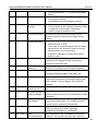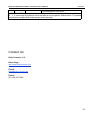
1
Kelly KLS-S
Brushless Motor Controller User’s Manual
V1.5.02
Kelly KLS-S Brushless Motor
Controller User’s Manual
Devices Supported:
KLS4812S
KLS7212S
KLS6018S
KLS7230S
KLS6025S
KLS6040S
KLS6030S
KLS7240S
Rev1.5.02
Sep.2015
Kelly KLS-S
Brushless Motor Controller User’s Manual
V1.5.02
Contents
Chapter 1 Introduction.............................................................................................. 2
1.1 Overview.............................................................................................................................. 2
Chapter 2 Features and Specifications................................................................. 3
2.1 General functions............................................................................................................... 3
2.2 Features...............................................................................................................................4
2.3 Specifications...................................................................................................................... 5
2.4 Name Regulation................................................................................................................5
Chapter 3 Wiring and Installation........................................................................... 6
3.1 Mounting the Controller..................................................................................................... 6
3.2 Connections...................................................................................................................... 11
3.3 Installation Check List......................................................................................................15
Chapter 4 Programmable Parameters................................................................ 16
4.1 Step 1.................................................................................................................................16
4.2 Step 2.................................................................................................................................20
4.3 Step 3.................................................................................................................................21
Chapter 5 Maintenance.......................................................................................... 23
5.1 Cleaning.............................................................................................................................23
5.2 Configuration.....................................................................................................................23
Table 1: LED CODES................................................................................................ 24
Contact Us:.................................................................................................................. 26
1
Kelly KLS-S Brushless Motor Controller User’s Manual
V1.5.02
Chapter 1 Introduction
1.1 Overview
This manual introduces the Kelly Small sinusoidal wave brushless BLDC motor controllers’
features, their installation and their maintenance. Read the manual carefully and thoroughly
before using the controller. If you have any questions, please contact the support center of Kelly
Controls, LLC.
Kelly’s programmable motor controllers provide efficient, smooth and quiet controls for
electric motorcycles, golf carts and go-carts, as well as industrial motor control. It is mainly
supposed to solve noise problems of BLDC motor driving application. The KLS-S motor
controller must be based on hall sensors type.KLS-S controller can not support sensorless
brushess motor for now.Compared to the traditional trapezoidal waveform control technology,
this technique based on sinusoidal wave driving technology to reduce the operation noise and
1/3 switching loss, which well meets the noise reduction and efficiency requirements in the
application of DC brushless motor. It uses high power MOSFET’s and, SVPWM and FOC to
achieve efficiencies of up to 99% in most cases. A powerful microprocessor brings in
comprehensive and precise control to the controllers. It also allows users to adjust parameters,
conduct tests, and obtain diagnostic information quickly and easily.People can program the KLS
controller on PC software and Android App.There is one more choice for customers to program
KLS controller now.The APP software is based on Tablet with Android OS.Customers may add a
Z-TEK USB to RS232 cable for programming KLS controller if they want to use Android Tablet.
Both PC software and Android APP can provide one screen to monitor the controller
parameters.Sometimes people can use a small Android Tablet as display device.
2
Kelly KLS-S Brushless Motor Controller User’s Manual
V1.5.02
Chapter 2 Features and Specifications
2.1 General functions
(1) Extended fault detection and protection. The LED flashing pattern indicates the fault
sources.Customers can read the error code in PC software or Android Tablet also.
(2) Monitoring battery voltage. It will stop driving if the battery voltage is too high and it will
progressively cut back motor drive power as battery voltage drops until it cuts out
altogether at the preset “Low Battery Voltage” setting.
(3) Built-in current loop and over current protection.
(4) Configurable motor temperature protection range.
(5) Current cutback at low temperature and high temperature to protect battery and controller.
The current begins to ramp down at 90℃ case temperature, shutting down at 100℃.
(6) The controller keeps monitoring battery recharging voltage during regen braking.
(7) Maximum reverse speed and forward speed can be configured between 20% and 100%
respectively and separately.
(8) A 4pin connector to RS232 port and a Z-TEK USB to RS232 cable allows for configuration,
programming and software upgrades using the tablet which must be based on Android OS
now.People can do the same things on PC software by using a standard USB to RS232
cable instead.
(9) Provision of a +5 volt and +12 volt output to supply various kinds of hall sensors.
(10) 5 switch inputs which are activated by connection to 12V. Default to throttle switch, brake
switch,reversing switch,forward switch and Boost switch.
(11) 2 analog 0-5V inputs that default to throttle input, and motor temperature input
(12) Copy signal of one of hall sensors.
(13) Configurable boost switch. Enables the maximum output power achievable if the switch is
turned on.
(14) 12V brake switch input used different port from motor temperature sensor.You can use
both brake switch and motor temperature sensor functions at the same time on the latest
version.Pin 25 is 12V brake switch input port.Pin1 is motor temperature sensor input port.
(15) Optional joystick throttle. A bi-symmetrical 0-5V signal for both forward and reversing.
(16) Configurable motor over-temperature detection and protection with the recommended
thermistor KTY84-130 or KTY84-150.
(17) 3 hall position sensor inputs. Open collector, pull up provided.
(18) Enhanced regen brake function. A novel ABS technique provides powerful and smooth
regen.The regen can happen at any speeds until zero speed.
Caution! The regen is not a safe function.Usually you may use the mechanical brake.
3
Kelly KLS-S Brushless Motor Controller User’s Manual
V1.5.02
2.2 Features
1) Intelligence with powerful microprocessor.
2) Synchronous rectification, ultra low drop, fast SVPWM and FOC to achieve very high
efficiency.
3) Electronic reversing.
4) Voltage monitoring on 3 motor phases, bus, and power supply.
5) Voltage monitoring on voltage source 12V and 5V.
6) Current sense on all 3 motor phases.
7) Current control loop.
8) Hardware over current protection.
9) Hardware over voltage protection.
10) Configurable limit for motor current and battery current.
11) Low EMC.
12) LED fault code.
13) Battery protection: current cutback, warning and shutdown at configurable high and low
battery voltage.
14) Rugged aluminum housing for maximum heat dissipation and harsh environment.
15) Rugged high current terminals, and rugged aviation connectors for small signal.
16) Thermal protection: current cut back, warning and shutdown on high temperature.
17) Configurable 60 degree or 120 degree hall position sensors.
18) Controller can do auto_Identification angle for different degrees of hall sensors.
19) Configurable high pedal protection: the controller will not work if high throttle is detected at
power on.
20) Current multiplication: Take less current from battery, output more current to motor.
21) Easy installation: 3-wire potentiometer will work.
22) Standard PC/Laptop computer to do programming.There is one more choice for customers
to program KLS controller.Standard Tablet with Android OS to do programming.Need a
Z-TEK USB TO RS232 cable for connecting the controller to App program in Tablet.
23) User program provided. Easy to use. No cost to customers.
24) Support motors with any number of poles.
25) Up to 70,000 electric RPM standard. (Electric RPM = mechanical RPM * motor pole
pairs;Motor pole pairs=Motor poles/2).
4
Kelly KLS-S Brushless Motor Controller User’s Manual
V1.5.02
2.3 Specifications
•Frequency of Operation: 20KHz.
•Standby Battery Current: < 0.5mA.
•5V or 12V Sensor Supply Current: 40mA.
•Controller supply voltage range: PWR, 18V to 90V for controllers rated equal or lower than
72V.
•Supply Current, PWR, 30mA Typical.
•Configurable battery voltage range, B+. Max operating range: 18V to 1.25*Nominal Voltage.
•Standard Throttle Input: 0-5 Volts(3-wire resistive pot), 1-4 Volts(hall active throttle).
•Throttle Input: 0-5 Volts. Can use 3-wire pot to produce 0-5V signal.
•Main Contactor Coil Driver<2A.
•Full Power Operating Temperature Range: 0℃ to 70℃(MOSFET temperature).
•Operating Temperature Range: -40℃to 100℃ (MOSFET temperature).
•Max Battery Current :Configurable.
2.4 Name Regulation
The name regulation of Kelly BLDC motor controllers:
KLS 72 30S
KLS:Kelly BLDC motor controller based on sinusoidal waveform which is supposed to
work with BLDC motor with three hall sensors.
72:72V batteries
30:The matched motor is 72V 3KW BLDC motor with hall sensors.
S:Mini case for the controller,and motor power≤4KW
Kelly KLSS Brushless Motor Controller
Model
10 seconds
Continuous
Current(Amp)
Current(Amp)
KLS4812S
120
50
KLS7212S
120
50
KLS6018S
240
100
KLS6025S
300
120
KLS6030S
350
150
KLS6040S
400
175
KLS7230S
300
120
KLS7240S
350
150
1.48V model: range of the battery voltage is 24V-48V.
1.60V model: range of the battery voltage is 24V-60V.
3.72V model: range of the battery voltage is 24V-72V.
Voltage(Volt)
24-48
24-72
24-60
24-60
24-60
24-60
24-72
24-72
5
Kelly KLS-S Brushless Motor Controller User’s Manual
V1.5.02
Chapter 3 Wiring and Installation
3.1 Mounting the Controller
The controller can be oriented in any position which should be as clean and dry as possible,
and if necessary, shielded with a cover to protect it from water and contaminants.
To ensure full rated output power, the controller should be fastened to a clean, flat metal
surface with four screws. Applying silicon grease or some other thermal conductive material to
contact surface will enhance thermal performance.
Proper heat sinking and airflow are vital to achieve the full power capability of the controller.
The case outline and mounting holes’ dimensions are shown in Figure 1,2,3,4,5.
Figure 1:KLS4812S KLS7212S mounting holes’ dimensions (dimensions in millimeters)
6
Kelly KLS-S Brushless Motor Controller User’s Manual
V1.5.02
Figure 2:KLS6018S mounting holes’ dimensions (dimensions in millimeters)
7
Kelly KLS-S Brushless Motor Controller User’s Manual
V1.5.02
Figure 3:KLS6025S mounting holes’ dimensions (dimensions in millimeters)
8
Kelly KLS-S Brushless Motor Controller User’s Manual
V1.5.02
Figure 4:KLS6030S KLS7230S mounting holes’ dimensions (dimensions in millimeters)
9
Kelly KLS-S Brushless Motor Controller User’s Manual
V1.5.02
Figure 5:KLS6040S KLS7240S mounting holes’ dimensions (dimensions in millimeters)
10
Kelly KLS-S Brushless Motor Controller User’s Manual
V1.5.02
3.2 Connections
3.2.1 Pin definition of KLS-S Controller
Figure 6: waterproof connector
DJ7091Y-2.3-11 Pin Definition
(14) REV_SW: Reverse switch input. Orange
(6) RTN: Signal return or power supply return. Black
(12) FWD: Forward switch White
(11) 12V:12V Source Red
(9) Relay: Main contactor driver. Blue
(7) PWR: Controller power supply (input). Pink
(25) 12V brake switch. Yellowish
11
Kelly KLS-S Brushless Motor Controller User’s Manual
V1.5.02
DJ7091Y-2.3-21 Pin Definition
(15) Micro_SW: Throttle switch input. Gray
(3) Throttle: Throttle analog input, 0-5V. Dark Green
(1) Temp: Motor temperature sensor input. Raddle.
(20) RTN: Signal return. Black
(8) Meter: Copy signal of hall sensors. Dark Blue
(4) 5V: 5V supply output, <40mA. Purple
(2) BOOST: Boost function. Brown
DJ7061Y-2.3-21 Pin Definition
(21) RTN:Signal return. Black
(5) 5V: 5V supply output,<40mA.Purple
(18) Hall A: Hall phase A. Yellow
(17) Hall B: Hall phase B. Dark Green
(16) Hall C: Hall phase C. Dark Blue
Notes:
1. All RTN pins are internally connected.
2. Meter function is to copy either of hall sensors.
3. Switch to 12V is active. Open switch is inactive.
Caution:
• Do not apply power until you are certain the controller wiring is correct and has been
double checked. Wiring faults will damage the controller.
• Ensure that the B- wiring is securely and properly connected before applying power.
• The preferred connection of the system contactor or circuit breaker is in series with the B+
line.
• All contactors or circuit breakers in the B+ line must have precharge resistors across their
contacts. Lack of even one of these precharge resistors may severely damage the controller
at switch-on.
12
Kelly KLS-S Brushless Motor Controller User’s Manual
V1.5.02
3.2.2 Wiring of KLS-S Controller
3.2.2.1 Standard wiring of KLS-S controller
Figure 7: KLS-S controller standard wiring
(Battery voltage can be used for controller supply)
13
Kelly KLS-S Brushless Motor Controller User’s Manual
V1.5.02
3.2.2.2 Optional wiring of KLS-S controller
The 12V input signal of the pin supplies the second braking function of the controller.
Figure 8: Wiring of brake switch(12V): 12V is provided by external source.
Figure 9: Wiring of brake switch(12V): 12V is provided by KLS-S controller on pin11
Figure 10: Wiring diagram for motor temperature sensor
NOTE:The motor temperature sensor and brake switch used the same I/O port on pin1.Both
functions can not be used at the same time.KLS controller can support KTY84-150 and
KTY84-130 thermistors.
14
Kelly KLS-S Brushless Motor Controller User’s Manual
V1.5.02
3.2.3 Communication Port
A 4pin connector to RS232 port is provided to communicate with host computer for calibration and
configuration.
Figure 8: RS232 Interface on 4pin connector to RS232 converter
Figure 9:SM-4P connector for communication interface on KLS-S controller
3.3 Installation Check List
Before operating the vehicle, complete the following checkout procedure. Use LED code as
a reference as listed in Table 1.
Caution:
• Put the vehicle up on blocks to get the drive wheels off the ground before beginning these
tests.
• Do not allow anyone to stand directly in front of or behind the vehicle during the checkout.
• Make sure the PWR switch and the brake is off
• Use well-insulated tools.
•
Make sure the wire is connected correctly
•
Turn the PWR switch on. The Green LED stay on steadily and Red LED turns off when the
controller operates normally. If this does not happen, check continuity of the PWR and
return.
15
Kelly KLS-S Brushless Motor Controller User’s Manual
V1.5.02
•
The fault code will be detected automatically at restart.
•
With the brake switch open, select a direction and operate the throttle. The motor should
spin in the selected direction. Verify wiring or voltage and the fuse if it does not. The motor
should run faster with increasing throttle. If not, refer to the Table 1 LED code, and correct
the fault as determined by the fault code.
•
Take the vehicle off the blocks and drive it in a clear area. It should have smooth
acceleration and good power.
Chapter 4 Programmable Parameters
KLS Configuration program allow users to set parameters according to the vehicle actual
working environment so as to be at its best.
The default parameters of the controller are not recommended for all applications. Make
sure set the proper parameters before making any test to avoid danger.
Customers can do program on PC software or Android App.The Android Tablet is
prefered.First of all,people need to do Identification angle function for KLS controller before
running the motor.The controller needs to be connected to batteries,motor and throttle before
Identification operation.That is to say,it is not enough to connect only power supply(PWR=pin7)
to batteries for Identification Angle operation.
Please download the instruction how to use Identification angle function from our website.
www.kellycontroller.com/support.php
4.1 Step 1
(1)Low Volt: The min voltage of reporting this fault - Range 18~90
Controller will not operate when battery voltage is near the value so as to protect battery.
Suggestion: Set according to the practical situation.By default,it is set at 18V.
(2)Over Volt: The max voltage of reporting this fault - Range 18~90
Controller will not operate when battery voltage is higher than the value so as to protect battery
and controller.
Suggestion: Set according to the practical situation.
By default,It is 60V for 48V controller.It is 80V for 60V controller.It is 90V for 72V controller.
Controller Rated voltage
48V
60V
72V
Under Voltage Range (V) Over Voltage Range(V)
18~60
18~80
18~90
18~60
18~80
18~90
Figure 4.1
16
Kelly KLS-S Brushless Motor Controller User’s Manual
V1.5.02
(3)Current Percent: Phase Current Percent. Range: 20~100
Functional description: The max motor current is (The Value * Peak Current of the Controller).
Suggestion: Factory default is 100%.
(4)Battery Limit: Battery Limit Current, Limit the max value of Battery Current. Range: 20~100
Functional description: Set max battery current so as to protect battery. A lower value means a
lower battery output current and better protective effect. But excessively low value will affect
acceleration.
Suggestion: Factory default is 100%.
(5)Identification Angle: Please download the instruction to how to use Identification angle
function from the website.
www.kellycontroller.com/support.php
If you can read 85 in Identification Angle item,that is to say,the system is stable and
normal.Please fill in 170 for Identification Angle item in user program.Then
please click Write button in user program.Please wait a few seconds before restart the power
supply.You will see some info on Monitor screen after power supply is
reset.If you see Reset error on the Monitor screen,that is to say,the auto_Identification is
finished.You can see 85 in the Identification Angle item again.And the controller will
blink error code.This is normal.Please reset the power supply again.Then everything will be
fine.The motor is ready to be drived by the KLS controller.
Range: 85 or 170,nothing else.
(6)TPS Low Err: Hall active pedal, if lower than the value, report the fault of TPS Type. Range:
0~20
(7)TPS High Err: Hall active pedal, if higher than the value, report the fault of TPS Type. Range:
80~100
As you may know,the output of hall throttle from Kelly is about from 0.86V to 4.2V.
Our controller will report 3.3 error code if the output of hall throttle is below 0.5V or above 4.5V
by default.
The controller will think the hall throttle is shorted or damaged if the output is beyond the range
from 0.5V to 4.5V.
You can adjust the threshold voltage below or above 0.5V.The controller will report the 3.3 code
to protect the system according to different types of hall throttle.
Because there are many different hall throttle suppliers in the world.The initial output can not be
always in the range of 0.5V to 4.5V.
But it doesn't make any differences if you choose 0-5V or 3-wire pot for the throttle type.That is
to say,these two settings are only useful for hall active throttle or pedal when you chose throtle
type at 2.
As the same goes,it is valid to adjust the high threshold voltage above 4.5V or below 4.5V.
Usually the hall output voltage is 4.2V Max.If you adjust it to lower value which is near 4.2V,it
may trigger the error code in normal way.
17
Kelly KLS-S Brushless Motor Controller User’s Manual
V1.5.02
(8)TPS Type: TPS Type, 1:0-5V 3-wire 0-5K pot,5K is normal,2K-20K can be used;2:Hall active
throttle or pedal. Range: 1~2
(9)TPS Dead Low: TPS Dead Zone Low. Range: 5~40
Functional description: Set throttle effective starting point
Suggestion: Set according to the practical situation, factory default is 20%*5V=1.0V.
(10)TPS Dead High: TPS Dead Zone High. Range: 60~95
Functional description: Set throttle effective ending point
Suggestion: Set according to the practical situation, factory default is 80%*5V=4.0V.
(11)Max output Fre: Max output frequency. Unit:Hz
Functional description:It will affect the top speed of the motor.
Suggestion: Set according to the practical situation, factory default is 1000Hz.Please don’t set it
1000Hz above.
(12)Max Speed: Max Speed [rpm]. Range: 0~10000 By default,it is set at 4000.
(13)Max Fwd Speed %: The forward speed of the percentage of maximum speed. Range:
20~100 By default,it is set at 100%
(14)Max Rev Speed %: The reverse speed of the percentage of maximum speed. Range:
20~100 By default,it is set at 100%
(15)PWM Frequency: Frequency of PWM operation. Unit:KHz
Functional description:20KHz is better for hub motor with strict quiet control.
Suggestion: Set according to the practical situation, factory default is 20KHz.Please don’t set it
20KHz above.
Value Range:10KHz or 20KHz
(16)Start-up H-Pedal:
Value range: Enable and Disable
Functional description: If enabled, the controller will detect the current pedal status at power up.
If throttle got effective output, the controller will report fault and not operate.
Suggestion: Set according to the practical situation, factory default is Enable.
(17)Brake H-Pedal:Releasing Brake High Pedal Disable
Value range: Enable and Disable
Functional description: If enabled, the controller will detect the current pedal status when
release the brake. If throttle got effective output, the controller will report fault and not operate.
Suggestion: Set according to the practical situation, factory default is Disable.
(18)NTL H-Pedal:Neutral position High Pedal Disable.Only useful when Three gears switch
18
Kelly KLS-S Brushless Motor Controller User’s Manual
V1.5.02
function is enabled.
If enable,the controller will detect the current pedal position or signal When the switch is in
neutral poistion.
If the throttle got effective output signal,the controller will not operate and report fault code.
Suggestion: Set according to the practical situation, factory default is Disable.
(19)Joystick function:
If enable,the controller can drive the motor on two directions without using any reversing switch.
Just one single throttle can drive the motor on forward and reversing direction.
The stick shift throttle firmware can be called wig-wag or joystick operation.It is only a software
function.Usually It is useful for electric boat project.You still can use the common 0-5K pot or
0-5V throttle for the controller.If you don't choose the joystick,you operated the throttle in this
way.The motor speed will increase when the throttle is from 0V to 5V.
If you enable joystick for this controller in user program,you will start the motor from 2.5V
position.2.6V to 5V is forward.2.4V to 0V is backward.
2.4V to 2.6V is the throttle dead zone.Customers can adjust the throttle dead zone in user
program also.
Please note the common throttle will spring back to original position if you release the throttle.
Suggestion:factory default is Disable.
(20)Three Gears switch:It is used for function of F-N-R control.
Please check the wiring diagram in the manual for F-N-R control.
Suggestion: Set according to the practical situation, factory default is Disable.
(20-A)Three Gears Switch
Value range: Enable and Disable
Functional description: If enabled, the Forward switch will be activated. Please see figure 4.1.
Suggestion: Set according to the practical situation, factory default is Disable.
(20-B)Foot Switch
Value range: Enable and Disable
Functional description: If enabled,the foot switch will be activated.The controller will not accept
the throttle signal if the foot switch is turned off. Please see figure 4.1.
Suggestion: Set according to the practical situation, factory default is Disable.
Configuration
Forward
FWD_SW
Foot Switch
Switch
(12)
OFF
OFF
Enable
Disable
ON
ON
x
Disable
Enable
x
Pin Status
REV_SW
(14)
OFF
ON
OFF
ON
OFF
ON
Foot
(15)
x
x
x
x
OFF
OFF
Running
Status
Neutral
Reverse
Forward
Neutral
Can’t operate
Can’t operate
19
Kelly KLS-S Brushless Motor Controller User’s Manual
Disable
Disable
x
x
x
x
V1.5.02
ON
OFF
OFF
ON
ON
ON
x
x
Reverse
Forward
Forward
Reverse
Note: X means can be on or off
Figure 4.2
(21)Boost:If enabled,the controller will output max power for a while.
Boost function is just full throttle position when you turn on boost switch even if the throttle is not
operated at all.
The boost function is still based on limiting of the motor current and battery current settings in
user program.
Suggestion: Set according to the practical situation, factory default is Disable.
(22)Foot switch:It is used for microswitch.If enabled,the controller will only accept the throttle
signal after received the valid foot switch signal.
If there is no foot switch signal,the controller will ignore the throttle signal.
Suggestion: Set according to the practical situation, factory default is Disable.
(23)Cruise Control:Value range: Enable and Disable
If enable,if you hold throttle at certain position about 3-4 seconds,the controller will get into
Cruise control.
Release throttle and turn the throttle again or turn on the brake switch will make the Cruise
control quit.
Suggestion:factory default is Disable.
(24)Change Direction:
If the direction is not what you expected after finish the Identification angle operation,please just
choose Change Direction item.
Please click Write button to activate Change Direction function.The motor direction will be what
you expected after the power supply is reset.
Suggestion:factory default is Disable.
4.2 Step 2
(1)Motor Poles: Motor Poles, The pair pole number*2. Range: 2~128
Suggestion: Set according to the real motor poles on the nameplate of the motor, factory default
is at 8.
(2)Speed Sensor Type: Speed Sensor Type, 2:Hal, 3:Resolver, 4:Line Hall. Range: 2~4
Different sensors type.By defualt,it is set at 2
20
Kelly KLS-S Brushless Motor Controller User’s Manual
V1.5.02
If you have a motor with 5V,Sin/Cosin,GND speed sensors,please choose it at 4.And please
inquire the KLS-8080IPS model before ordering.
(3)Resolver Poles: Resolver Poles, The pair pole number*2. Range: 2~32
It is only used for the Resolver sensor type.
(4)Motor Temp Sensor: Motor Temp Sensor, 0:None, 1:KTY84-130 or 150. Range: 0~1
High Temp Cut Out °C: Motor High Temp Cut Out, nominal value 130°C. Range: 60~170
Resume ° C: Motor High Temp Resume Temp, nominal value 110 ° C.The controller will
resume work when the motor temp is at 110 degrees inside. Range: 60~170
(5)Line Hall Zero:It is only useful when the speed sensor is at 4.
Zero-Crossing point of Sine/Cosine linear hall sensors output signal.Usually the Sine/Cosine
speed sensor supplier provided sensors with 2.5V or 3.0V zero-crossing point.
You can change it back between 2.5V and 3.0V if the motor can not run.
Suggestion: Set according to the practical situation, factory default is 613(3.0V) for Mars
1114/1115/1302/1304 from Motenergy company.
Value Range:0-1023 maps 0-5V
(6)Line Hall Amplitude:The position signal based on Zero-crossing point.It is only useful when
the speed sensor is at 4.
For example,if the Line hall Amplitude is 1.1V,the signal output of Sine/Cosine sensors is from
1.9V to 4.1V.(3-1.1=1.9V;3+1.1V=4.1V)
Value Range:0-1023 maps 0-5V
(7)Line Hall High Err:It is only useful when the speed sensor is at 4.
If the signal output of Sine/Cosine speed sensor is above this setting,the controller will report
hall error.Please adjust Line Hall High Err to a higher value to eliminate this error.
Value Range:0-1023 maps 0-5V
(8)Line Hall Low Err:It is only useful when the speed sensor is at 4.
If the signal output of Sine/Cosine speed sensor is below this setting,the controller will report
hall error also.Please adjust Line Hall Low Err to a lower value to eliminate this error.
Value Range:0-1023 maps 0-5V
4.3 Step 3
(1)RLS_TPS Brk %: RLS TPS Braking Percent, the percent of Releasing Pedal BRK in max
braking. Range: 0~50
This is used to adjust the regen current of releasing throttle regen mode type.The regen will
happen as long as the throttle is released completely.
21
Kelly KLS-S Brushless Motor Controller User’s Manual
V1.5.02
Factory set is 0
(2)NTL Brk %: NTL Braking Percent, the percent of Neutral Braking in max braking. Range:
0~50
Only useful when you enable Three gears switch in user program.
The regen will happen when you turn F-N-R switch from Forward or backward to Neutral
position.
Factory set is 0
(3)Accel Time: Accel Time, the time of TPS Torque from 0 to max, accuracy 0.1s, 5 is equal to
0.5s. Range: 1~250
Factory set is 10
(4)Accel Rls Time: Accel Release Time, the time of TPS Torque from max to 0, accuracy 0.1s.
Range: 1~250
Factory set is 1
(5)Brake Time: Brake Time, the time of Brake Torque from 0 to max, accuracy 0.1s. Range:
1~250
Factory set is 15
(6)Brake Rls Time: Brake Release Time, the time of Brake Torque from max to 0, accuracy 0.1s.
Range: 1~250
Factory set is 1
(7)BRK_SW Brk %: BRK_SW Braking Percent, the percent of BRK_SW in max braking. Range:
0~50
The brake switch regen mode.You have to turn on the brake switch after the throttle is released
for the regen to occur.
Factory set is 10
(8)Torque Speed KP: Speed Percent Kp in Torque Mode. Range: 0~10000 Factory set is 3000
Torque Speed KI: Speed Integral Ki in Torque Mode. Range: 0~500 Factory set is 80
Speed Err Limit: Speed Error Limit in Torque Mode. Range: 50~4000 Factory set is 1000
These three parameters are used for PID adjustment.
If you think the acceleration performance is very very strong,please adjust them to a lower value
respectively.
(9)Change Dir brake:Value range: Enable and Disable
It is only useful when you Enable the joystick function.
If you want to get swift direction changing by using joystick function,you may enable Change Dir
brake item in user program.
It will help the motor change the direction of motor quickly after you shift throttle from 0V to 5V,or
22
Kelly KLS-S Brushless Motor Controller User’s Manual
V1.5.02
from 5V to 0V.
Suggestion:factory default is Disable.
Note: Thermistor is optional. Default to KTY84-130 or 150
Chapter 5 Maintenance
There are no user-serviceable parts inside the controllers. Do not attempt to open the
controller as this will void your warranty. However, periodic, exterior cleaning of the controller
should be carried out.
The controller is a high powered device. When working with any battery powered vehicle,
proper safety precautions should be taken that include, but are not limited to, proper training,
wearing eye protection, avoidance of loose clothing, hair and jewelry. Always use insulated
tools.
5.1 Cleaning
Although the controller requires virtually no maintenance after properly installation, the following
minor maintenance is recommended in certain applications.
• Remove power by disconnecting the battery, starting with battery positive.
• Discharge the capacitors in the controller by connecting a load (such as a contactor coil,
resistor or a horn) across the controller’s B+ and B- terminals.
• Remove any dirt or corrosion from the bus bar area. The controller should be wiped with a
moist rag. Make sure that the controller is dry before reconnecting the battery.
• Make sure the connections to the bus bars, if fitted are tight. To avoid physically stressing
the bus bars use two, well-insulated wrenches.
5.2 Configuration
You can configure the controller with a host computer through either an RS232 or USB port.
• Disconnect motor wiring from controller for configuring existing parameters in the user
program or Android APP. If this operation is too much extra job for you, please make sure
the motor must be stopped before programming.
• The controller may display fault code, but it doesn't affect programming or
configuration.But it will affect the Identification angle operation.Please try to eliminate the
error codes before Identification angle operation.
• Use a straight through RS232 cable or USB converter provided by Kelly to connect to a
host computer. Provide >+18V to PWR(for a 24V controller, provide >+8V). Wire power
supply return(supply negative) to any RTN pin.
23
Kelly KLS-S Brushless Motor Controller User’s Manual
•
V1.5.02
KLS controller requires a 4pin connector to Kelly RS232 Converter to support the
communication.And customers may need a Z-TEK USB cable for Tablet with Android OS.
Customers may download PC software or Android APP to program the controller
before running the motor.You may do Identification angle operation for brushless
motor after running the software or Android APP.Every item in the configuration
program can show the explanation automatically when you click it.
Caution:
•Make certain that the motor is connected before trying to run Identification angle
function in the configuration software.The controller needs to be connected to
batteries,motor and throttle before Identification operation.That is to say,it is not
enough to connect only power supply(PWR=pin7) to batteries for Identification Angle
operation.
•Configuration software will be regularly updated and published on the website. Please
Update your Configuration Software regularly. You must uninstall the older version
before updating.
•Please try to use Identify function for motor and hall sensors in the user program
Table 1: LED CODES
Green LED Codes
LED Code
Green Off
Green On
Green & Red are both
On
Explanation
No power or
switched off
Normal operation
Solution
1. Check if all wires are correct.
2. Check fuse and power supply.
That’s great! You got solution!
1. Software needs upgrading.
2. Supply voltage too low or battery too high
3. The controller is damaged. Contact Kelly about a
warranty repair.
Red LED Codes
LED Code
1,1
¤
¤
Explanation
Automatic error
identification
1,2
¤
¤¤
Over voltage error
Solution
1. Wrong wiring of motor phase line or hall.
Please suspend the motor when enable
Auto-Identify function.
2. Battery voltage is too high for the controller.
Check battery volts and configuration.
3. Regeneration over-voltage. Controller will have
cut back or stopped regen.
24
Kelly KLS-S Brushless Motor Controller User’s Manual
1,3
¤
¤¤¤
Low voltage error
1,4
¤
¤¤¤¤
Over temperature
warning
2,1
¤¤
¤
Motor did not start
2,2
¤¤
¤¤
Internal volts fault
2,3
¤¤
¤¤¤
Over temperature
2,4
¤¤
¤¤¤¤
3,1
¤¤¤ ¤
Throttle error at
power-up
Frequent reset
3,2
¤¤¤ ¤¤
Internal reset
3,3
¤¤¤ ¤¤¤
3,4
¤¤¤ ¤¤¤¤
4,1
¤¤¤¤ ¤
4, 2
¤¤¤¤ ¤¤
4, 3
¤¤¤¤ ¤¤¤
V1.5.02
4. This only accurate to ± 2% upon Overvoltage
setting.
1. The controller will clear after 5 seconds if battery
volts returns to normal.
2. Check battery volts & recharge if required.
1. Controller case temperature is above 90℃.
Current will be limited. Reduce controller loading
or switch Off until controller cools down.
2. Clean or improve heatsink or fan.
Motor did not reach 25 electrical RPM within 2
seconds of start-up. Hall sensor or phase wiring
problem.
1. Measure that B+ & PWR are correct when
measured to B- or RTN.
2. There may be excessive load on the +5V supply
caused by too low a value of Regen or throttle
potentiometers or incorrect wiring.
3. Controller is damaged. Contact Kelly about a
warranty repair.
The controller temperature has exceeded 100℃. The
controller will be stopped but will restart when
temperature falls below 80℃.
Throttle signal is higher than the preset ‘dead zone’ at
Power On. Fault clears when throttle is released.
May be caused by over-voltage, bad motor
intermittent earthing problem, bad wiring, etc.
May be caused by some transient fault condition like
a temporary over-current, momentarily high or low
battery voltage. This can happen during normal
operation.
Hall throttle is open When the throttle is repaired, a restart will clear the
fault.
or short-circuit
Non-zero throttle on Controller won’t allow a direction change unless the
throttle or speed is at zero. Fault clears when throttle
direction change
is released.
Regen or Start-up Motor drive is disabled if an over-voltage is detected
at start-up or during regen. The voltage threshold
over-voltage
detection level is set during configuration.
1. Incorrect or loose wiring or a damaged hall sensor.
Hall sensor error
2. Also be caused by incorrect hall angle
configuration (60 degree or 120 degree)
Motor temperature has exceeded the configured
Motor
maximum. The controller will shut down until the
over-temperature
25
Kelly KLS-S Brushless Motor Controller User’s Manual
V1.5.02
motor temperature cools down.
The Red LED flashes once at power on as a confidence check and then normally stays
Off. “1, 2” means the Red flashes once and after a second pause, flashes twice. The pause
time between multiple flash code groups is two seconds.
Contact Us:
Kelly Controls, LLC
Home Page:
http://www.KellyController.com
E-mail:
[email protected]
Phone:
(01) 224 637 5092
26