1
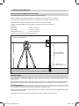
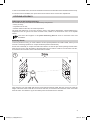
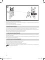
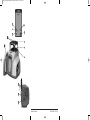
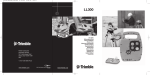
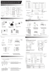
140232_00_Umschlag_LL300N_140232_Umschlag_LL300N 19.02.14 13:59 Seite 1 LL300N Trimble - Spectra Precision Division 5475 Kellenburger Road Dayton, Ohio 45424 U.S.A. +1-937-245-5600 Phone © 2013, Trimble Navigation Limited. All rights reserved PN 95721-00 Rev. C (02/14) 140232_00_Umschlag_LL300N_140232_Umschlag_LL300N 19.02.14 13:59 Seite 1 LL300N Trimble - Spectra Precision Division 5475 Kellenburger Road Dayton, Ohio 45424 U.S.A. +1-937-245-5600 Phone © 2013, Trimble Navigation Limited. All rights reserved PN 95721-00 Rev. C (02/14) 140232_00_Umschlag_LL300N_140232_Umschlag_LL300N 19.02.14 13:59 Seite 2 3 5 4 1 2 8 7 10 9 6 13 11 12 Printed in Germany 95721-00 Rev. C (02/14) TABLE OF CONTENTS FOR YOUR SAFETY Important Information COMPONENTS POWER SUPPLY Installing the Batteries Operating Time Charging the Batteries HOW TO USE THE LASER Laser Setup Self-leveling and Height (HI) Change Alert Manual-/Single Slope Mode OPERATING EXAMPLES Determining the Height of Instrument (HI) Marking Heights Vertical Application LEVELING ACCURACY Influences on Leveling Accuracy Checking Calibration MAINTENANCE AND CARE SYSTEM CLEANING PROTECTING THE ENVIRONMENT WARRANTY SPECIFICATIONS GB 5 5 6 6 6 6 7 7 7 7 7 8 8 8 8 9 9 9 10 10 10 11 11 FOR YOUR SAFETY For hazardless and safe operation, read all the user guide instructions. • Use of this product by people other than those trained on this product may result in exposure to hazardous laser light. • Do not remove warning labels from the unit. • The laser is subject to class 2 (<3,4mW, 630...680nm). • Due to the small diameter beam, watch and secure the course of the beam in remote areas. • Never look into the laser beam or direct it to the eyes of other people. • Always operate the unit in a way that prevents the beam from getting into people’s eyes. • If initial service is required, which results in the removal of the outer protective cover, removal must only be performed by factory-trained personnel. Caution: Use of other than the described user and calibration tools or other procedures may result in exposure to hazardous laser light. Caution: Using different than described at the LL300N user guide, may result in unsafe operation. Important Information The Model LL300N is a simple-to-use tool that allows one or more workers to take accurate horizontal measurements at distances between 3 ft (1 m) and 650 ft (200 m) using a hand-held or rod-mounted receiver. • Always place the laser in the middle of the working area. • Tripod/wall mount operation is recommended for distances over 20 m (65 ft). • Check the accuracy regularly. • Stable mounting is necessary for secure operations. • Keep the glass of the instrument clean. 5 131050_01_LL300_GB.indd 5 30.10.13 08:12 COMPONENTS Buttons 1 Power Button 2 Manual Button Control indicators 3 Leveling Indicator 4 Manual/HI-Warning Indicator 5 Battery Indicator Elements of the unit 6 Infrared Receiver (for remote control) 7 Rotor Cage 8 Sighting Guides 9 Beam Aperture/Prism Cap 10 Handle 11 Battery Door 12 5/8x 11 Tripod Mounts 13 Rubber Feet POWER SUPPLY Before using the unit for the first time, install alkaline or rechargeable batteries. If rechargeable are used, first recharge the batteries. See battery section. The Ni-Cad and Ni-MH batteries may contain small amounts of harmful substances. Be sure to charge the battery before using it for the first time, and after not using it for an extended length of time. Charge only with specified chargers according to device manufacturer’s instructions. Do not open battery, dispose of in fire or short circuit; it may ignite, explode, leak or get hot causing personal injury. Dispose in accordance with all applicable federal, state, and local regulations. Keep the battery away from children. If swallowed, do not induce vomiting. Seek medical attention immediately. Installing Batteries Remove the battery door by turning the center screw 90° counterclockwise. Insert batteries (or a rechargeable battery pack) into the housing so that the negative poles are on the bigger battery spiral springs. DO NOT REMOVE RECHARGEABLE BATTERIES FROM THEIR HOLDER AND INSTALL ALKALINE BATTERIES, SEVERE DAMAGE TO UNIT WILL RESULT IF CHARGING IS ATTEMPTED. Install the battery door and tighten it by turning the center screw 90° clockwise. A mechanical switch prevents alkaline batteries from being charged. Only the original rechargeable battery pack allows charging within the unit. Any other rechargeable batteries have to be charged externally. Operating Time Rechargeable batteries permit an operating time of approx. 45 hours in rotation. Alkaline batteries (AIMn) permit an operating time of approx. 90 hours in rotation. The following factors reduce the operating time: • frequent self-leveling due to wind or vibration; • extreme temperatures; • old rechargeable batteries or rechargeable batteries with memory-effect; • using batteries of different capacities. Remove all batteries at the same time. Never use batteries with different capacities. Only use new (charged) batteries (rechargeable). Low voltage is indicated by the slow flashing battery indicator (5). 6 131050_01_LL300_GB.indd 6 30.10.13 08:12 Charging the batteries The charger requires approx. 10 hours to charge empty rechargeable batteries. For this charging, connect the plug of the charger to the recharge jack of the unit. New or long-time out-of-use rechargeable batteries reach their best performance after being charged and recharged five times. The batteries should only be charged when the laser is between 50° F and 104° F (10° C to 40° C) Charging at a higher temperature may damage the batteries. Charging at a lower temperature may increase the charge time and decrease the charge capacity, resulting in loss of performance and shortened life expectancy. HOW TO USE THE LASER Laser Setup Position the unit horizontally (tripod mount and rubber feet downward!) on a stable platform, wall mount, or tripod at the desired elevation. Press the power button (1) to turn on the unit. The LEDs (3, 4 and 5) are turned on for 3 seconds. Self-leveling will start at once. The unit is leveled when the leveling indicator (3) is no longer flashing (once every second). The rotor will not spin until the unit is leveled. For the first five minutes after the laser self levels, the LED lights solid then flashes every four seconds to let you know the laser is still level. In order to switch the unit off, press the power button (1) again. If the laser is positioned beyond its self-leveling range of ±8%, the manual and leveling indicators flash simultaneously and a warning sound is emitted. Reposition the laser within its self-leveling range. Self-leveling, Height Change (HI) Alert Once turned on, the unit automatically levels itself in ranges of 8% (± 0.8 m / 10 m). In order to recognize the leveling process at the measuring area and in order not to mark faulty heights during this operation, the rotation stops. Once leveled, the unit constantly monitors its level condition. The height change (HI) alert is activated 5 minutes after self-leveling was performed and the laser is rotating at 600 min-1. Level errors > 30 mm/10 m put the unit into alert mode because they are generally caused by a disturbance that could lead to inaccurate measurements. When entering into alert mode, the prism stops, the laser beam turns off, a warning sound is heard and the HI Warning LED (4) flashes 2 x per second. Turn the unit off and then on again. To ensure your former elevation, now you have to check or arrange the exact height. Manual Mode/Single Slope Mode When you press the manual button (2) on the laser, the remote control, or the receiver-remote control, the laser is set from automatic self-leveling mode to Manual mode. Manual mode is indicated by the flashing (once every second) red LED (4). In Manual mode, the Y-axis can be sloped by pressing the Up- and Down-Arrow-buttons on the remote control. Additionally, the X-axis can be sloped by pressing the Left- and Right-Arrow-buttons on the remote control. When you press the manual button again on the remote control, the laser is set into Single Slope mode. This is indicated by the flashing red (4) and green (3) LEDs (once every second). In Single Slope mode, the Y-axis can be sloped by pressing the Up- and Down-Arrow-buttons on the remote control, while the X-axis remains in automatic self leveling mode (e.g. when setting up ramps or drive ways). The Height change (HI) alert is still active. Pressing the manual button at the laser or remote control again, changes the laser back to automatic selfleveling mode as indicated by the flashing green LED (3). 7 131050_01_LL300_GB.indd 7 30.10.13 08:12 OPERATING EXAMPLES Determining the Height of Instrument (HI) The height of instrument (HI) is the elevation of the laser’s beam. The HI is determined by adding the grade-rod reading to a benchmark or known elevation. Set up the laser and place the grade rod on a job-site benchmark (BM) or known elevation. Slide the receiver up/down the grade rod until it shows an on-grade reading. Add the grade-rod reading to the benchmark to determine the height of instrument. Example: Benchmark = 30.55 m (100.23 ft) Rod reading = +1.32 m (+4.34 ft) Height of instrument = 31.87 m (104.57 ft) Use this HI as a reference for all other elevations. Height of Instrument (HI) LL300 HI Rod Reading 1.32 m (4.34 ft) Benchmark 30.55 m (100.23 ft) HI = Rod Reading + Benchmark HI = 1,32 m + 30,55 m = 31,87 m (4.34 ft + 100.23 ft = 104.57 ft) Marking Heights Set up the laser in horizontal mode (e.g., using a tripod or wall mount) so that the laser beam is at the desired height. When working without a tripod or wall mount, set up the laser on a stable surface and measure the height difference between laser beam and desired height by using a ruler and mark the measured height again. Vertical Application Level the tripod and allow the laser to level in automatic self-leveling mode. Push the manual mode button and change the laser’s position on the tripod for vertical alignment by using the vertical mounting thread. Rotate the laser until the vertical laser plane aligns with the receiver’s on-grade position. 8 131050_01_LL300_GB.indd 8 30.10.13 08:12 In order to avoid offset errors, the receiver should be used close to the elevation where the laser has been set up. If a remote control is available, the up and down arrow buttons can be used for fine adjustments. LEVELING ACCURACY Influences on the leveling accuracy The overall accuracy of the unit can be influenced by many factors: • factory accuracy; • temperature of the unit; • ambient influences like rain, wind and temperature. The factor that influences on the unit’s accuracy most is the ambient temperature. Vertical differences in temperature near the ground can divert the laser beam, similar to the heat waves seen on hot asphalt streets. This factor also applies to all optical measuring devices such as automatic levels and theodolites. Accuracy Check To ensure job-site accuracy, you need a distance of 20 m (65 feet) between two walls A and B, where you will execute 4 measuring operations on a tripod as follows (transit measurement). Set the unit horizontally on a tripod near wall A and switch it on with the plus X-axis pointing towards wall A. After the unit is level, mark the height of the laser beam using a receiver at wall A. Turn the entire unit 180°, let it self-level and mark the center of the laser beam at wall B. Now, place the unit near wall B with the plus X-axis pointing towards wall B. After the unit is level, mark the height of the laser beam at wall B. Turn the entire unit 180°, let it self-level and mark the center of the laser beam at wall A. The difference (h) of the marked points at wall A shows the deviation. 9 131050_01_LL300_GB.indd 9 30.10.13 08:12 If the unit is within its working accuracy limits (± 20”) the maximum difference from true level at 20 m (65 ft.) + 20 m (65 ft.) = 40 m (130 ft.) is 4 mm (3/16 inch). Repeat the above steps for “minus X” and for “plus-” and “minus Y”, so that a measurement for all four axes of the unit have been performed. The accuracy of the detector has to be regarded. PROTECTING THE UNIT Do not expose the unit to extreme temperatures or temperature changes (do not leave inside the car). The unit is very robust and can resist damage if dropped even from tripod height. Before continuing your work, always check the leveling accuracy. See Accuracy Check section. The laser is water proof and can be used indoors and outdoors. CLEANING AND MAINTENANCE Dirt and water on the glass parts of laser or prism will influence beam quality and operating range considerably. Clean with cotton swabs. Remove dirt on the housing with a lint-free, warm, wet and smooth cloth. Do not use harsh cleansers or solvents. Allow the unit to air dry after cleaning it. PROTECTING THE ENVIRONMENT The unit, accessories and packaging should be recycled. This manual is made of non-chlorine recycling paper. All plastic parts are marked for recycling according to material type. Do not throw used batteries into the garbage, water or fire. Remove them in compliance with environmental requirements. 10 131050_01_LL300_GB.indd 10 30.10.13 08:12 WARRANTY Trimble warrants the LL300N to be free of defects in material and workmanship for a period of 5 years. Trimble or its authorized service center will repair or replace, at its option, any defective part, or the entire product, for which notice has been given during the warranty period. If required, travel and per diem expenses to and from the place where repairs are made will be charged to the customer at the prevailing rates. Customers should send the product to Trimble Navigation Ltd. or the nearest authorized service center for warranty repairs or exchange, freight prepaid. Any evidence of negligent, abnormal use, accident, or any attempt to repair the product by other than factory-authorized personnel using Trimble certified or recommended parts, automatically voids the warranty. The foregoing states the entire liability of Trimble regarding the purchase and use of its equipment. Trimble will not be held responsible for any consequential loss or damage of any kind. This warranty is in lieu of all other warranties, except as set forth above, including any implied warranty merchantability of fitness for a particular purpose, are hereby disclaimed. This warranty is in lieu of all other warranties, expressed or implied. SPECIFICATIONS Leveling Accuracy1,3: Rotation Speed: Operating Range (Diameter)1,2: Laser Type: Laser Class: Self-Leveling Range: Leveling Time: Leveling Indicators: Laser Beam Diameter1: Power Source: Operating Temp.: Storage Temp.: Tripod Mounts: Weight: Low voltage indication: Low voltage disconnection: < ± 15 arc seconds, < ± 2.2 mm/30 m (< ± 3/32in./100 ft) 600 rpm 400 m (1300 feet) 635 nm Class 2, <3.4 mW; t< 0.25 seconds approx. ± 8% (approx. ± 4,8°) approx. 30 sec LED flashes approx. 8 mm at the laser 4 x D-cell NiMH or alkaline batteries (LR20) -20° C ... 50° C (-4° F...122° F) -20° C ... 70° C (-4° F...158° F) 5/8 x 11 horizontally and vertically 2,7 kg flashing/shining of the battery indicator unit shuts off 1) at 21° Celsius 2) under optimal atmospheric circumstances 3) along the axis DECLARATION OF CONFORMITY We Trimble Kaiserslautern GmbH declare under our sole responsibility that the product LL300N to which this declaration relates is in conformity with the following standards EN 61000-6-3:2007 + A1:2010, EN 61000-6-2:2005 and EN 60825-1:2007 following the provisions of directive Electromagnetic compatibility 2004/108/EC. The managing director 11 131050_01_LL300_GB.indd 11 30.10.13 08:12 140232_00_Umschlag_LL300N_140232_Umschlag_LL300N 19.02.14 13:59 Seite 2 3 5 4 1 2 8 7 10 9 6 13 11 12 Printed in Germany 95721-00 Rev. C (02/14) 140232_00_Umschlag_LL300N_140232_Umschlag_LL300N 19.02.14 13:59 Seite 1 LL300N Trimble - Spectra Precision Division 5475 Kellenburger Road Dayton, Ohio 45424 U.S.A. +1-937-245-5600 Phone © 2013, Trimble Navigation Limited. All rights reserved PN 95721-00 Rev. C (02/14)