1
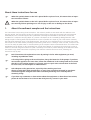
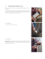
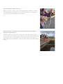
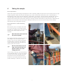
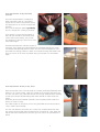
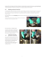
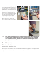
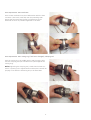
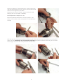
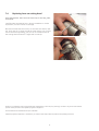
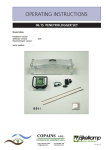
OPERATING INSTRUCTIONS
04.23 SEDIMENT CORE SAMPLER, TYPE BEEKER
Contents
About these instructions for use ....................................................................................................................... 2
1. About the sediment sampler and the instructions ........................................................................................ 2
2. Preparing the sampler for use ...................................................................................................................... 3
3. Using the sampler ........................................................................................................................................ 5
4. Taking the sample ........................................................................................................................................ 7
5. Further processing of the sample ................................................................................................................. 9
6. Extra options with the extended set 04.23.SB ............................................................................................ 10
6.1 The hydraulic extrusion system ........................................................................................................ 10
6.2 Working method in the field ............................................................................................................ 11
6.3 Dividing the sample into smaller tubes ............................................................................................. 13
7. Maintenance ............................................................................................................................................. 16
7.1 General maintenance ...................................................................................................................... 16
7.2 Maintenance of taps and connectors ............................................................................................... 17
7.3 Replacing cutting ring and/or membrane in the cutting head ........................................................... 17
7.4 Replacing hose on cutting head ....................................................................................................... 20
P.O. Box 4, 6987 ZG Giesbeek, NL
T +31 313 880200
F +31 313 880299
E [email protected]
© February 2005
www.eijkelkamp.com
1
M1.04.23.E
About these instructions for use
When the symbol shown on the left is placed before a piece of text, this means that an important instruction follows.
!
When the symbol shown on the left is placed before a piece of text, this means that an important warning follows pointing out a risk of injury to the user or damage to the device.
1.
About the sediment sampler and the instructions
The instructions have a strong visual orientation. This makes it possible to start work with the sediment core
sampler quickly. The first section consists of instructions that apply to both sets (04.23.SA basic and 04.23.SB
extended set). This is followed by the extra possibilities offered by the extended set (04.23.SB). The sets are
intended for a maximum sampling depth of 5 metres. This depth can be increased by adding extension rods.
Taking samples in flowing water becomes difficult or even impossible at a depth of just a few metres. However,
the bed will be extremely stony in fast flowing water. The sampler is not intended for this. The piston that moves
the sample into the tube and the possibility of hammering mean that in a sandy or other firm bed, a sample of 50150 cm can easily be taken. Bear in mind that driving in the sampler involves a substantial thrust. This means that
withdrawal can be difficult or risky, especially from a small boat (danger of capsizing). Fixing the boat in place in
relation to the bed using two anchors or spuds is necessary at all times to prevent twisting of the sediment cutter.
First read through these instructions completely. Then take the materials and set to work, following the
instructions step by step.
Each illustration with explanations starts by stating in italics what equipment you need,
including any additional items.
A few days before going to the work location, charge the batteries of the pumps. If you have
not used the appliance for some time, inflate the membrane in the cutting head once to check
that this is still working properly. It is always easier to repair leaks at home than in the field.
For such cases, see the chapter on “Maintenance”.
Take adequate safety precautions, especially when working on a boat.
Choose a stable boat with enough space, or work from a platform mounted on two boats
connected together alongside each other. Constantly balancing in an unsteady boat is
extremely tiring!
If you have any comments or observations about the equipment or about these instructions,
please do not hesitate to let us know! We wish you every success in your work.
2
2.
Preparing the sampler for use
Requirements: Piston rod, piston, collar, cutting head, sample tube, bucket
with water.
Check that the piston rings at the top of the piston and the rubber scrapers at
the bottom of the piston are completely undamaged. If in doubt, replace
them. If one of the piston rings is damaged, taking the sample or discharging
it will be extremely difficult or even impossible.
Extra requirements:Dip piston and cutting head in water.
Extra requirements:Push and twist the piston into the cutting head, with the rubber scrapers first.
Important: Position the hole for the piston rod directly opposite one of the
strips in the cutting head frame. The strips of this frame, the central bolt and
the hole are then lined up.
3
Extra requirements:Take the sample tube and insert it into the frame.
Push-twist it carefully over the piston rings, taking care not to damage these.
Extra requirements:Place the collar at the top of the frame. Check that the hole for the piston rod
is in line with the hole in the piston. Otherwise rotate the collar by 180°.
Extra requirements:Tighten the wing nuts firmly.
Check the tightness of these after taking each sample.
4
Extra requirements:Push the piston rod through the collar and
screw the piston rod into the piston
loosely.
3.
Using the sampler
Extra requirements: Extension hose and
pressure pump.
Hang both pumps on your belt (the
pressure pump on the right). Unwind the
extension hose from the spool and connect
it to the cutting head hose and the pressure
pump hose. Apply pressure (2 bars is
always enough) with the pressure pump
and check that the pressure does not fall
again. If there is any leakage, it may be
necessary to replace the O-rings or tighten
one of the connections (see maintenance).
The piston is now fixed tightly into the
cutting head and will not slip while the
sampler is being lowered.
Make sure that you release the
pressure before taking a sample!
Extra requirements: Non-stretch cord.
Hook a non-stretch cord to the piston rod. A nylon or polypropylene cord has
too much elasticity; it will make sampling much more difficult and may cause
considerable compaction of the sample. The original polyester-Dyneema cord
has a non-elastic core of extremely strong Dyneema which makes it possible to
keep the piston fixed perfectly at a stationary height, so that no compaction
can occur even at considerable sampling depths.
5
Extra requirements: Beaker with water.
When the sample is taken, there must be water above the piston. If you are
taking samples in shallow water (<1.5 m) then pour water on to the piston
first. This will prevent malfunction of the piston.
Extra requirements: Extension rods, T-shaped handle with beating head or
handle with detachable grip.
Screw no more than three metres of extension rods to the collar at one time.
You can add more rods while you are lowering the sampler into the water. Use
the beating head for harder sediments, the normal type for soft sludge, i.e.
when hammering is unnecessary. In case of doubt, fit the T-piece with beating
head.
6
4.
Taking the sample
Extra requirements:Lower the sampler, while fitting extra extension rods if necessary. Make sure that the hose connector does not get
caught anywhere. When the sampler feels lighter, you have reached the solid bottom (the “nautical depth”).
Depending on how much very thin sediment (“thick water”) you expect, pull the sampler upwards and a little to
one side. Most inland water has a barely perceptible thin sediment layer of twenty to thirty centimetres, but
situations are known where the sampler had to be raised by several metres before it was above the extremely soft
sediment. You must also move the sampler sideways so that you do not cut into the hole you have already
disturbed and the cloudy water above it.
Extra requirements: Impact absorbing
hammer
Now pull the piston cord tight and stand
on it or fix the cord in some other way to
the edge of a (stable!) boat. The piston will
remain at the same height from now
onwards.
Now disconnect the hose from
the pressure pump.
The sampler will often sink down under its
own weight. Push the sampler down
further. If you do not achieve the desired
sample length in this way, then take the
impact absorbing hammer and drive the
cutter further into the bed.
N.B: Do not hammer for too
long, since you will have to
pull the cutter out of the
sludge yourself!
If the current is strong or you are working
at considerable depth (> 5 m), you should
not push too hard; you should only drive
the sampler into the bed with hammer
strokes (or brief pushes with the arms) to
prevent bending or distortion of the rods.
7
Extra requirements: Push-pull handle,
spanners.
Once the required depth is reached (or
when hammering has no more effect),
replace the air hose in the pressure pump
and apply two to no more than three bars
pressure.
Then pull the sampler upwards gradually
and in a straight line. Jerking is pointless.
If you attach a cord to the two halves of
the push-pull handle (so that these parts
cannot fall into the water), you can use
this accessory to help you pull from a more
favourable height.
Dismantle the extension rods two by two if
necessary. If you shake the rods backwards and forwards slightly, the screw
connections will generally become loose. You can leave one extension rod in
place without causing problems. “Row” the sampler through the water a few
times to rinse it off as much as possible. Bring it on board or to the water’s
edge.
Extra requirements: Bucket (in set), brush.
Place the sampler more or less vertically in a bucket (preferably filled with clean
water) or on a clean surface. Clean the outside of the sampler with the brush.
You can now see if you pulled the sampler far enough upwards before starting
to take your sample (reasonably) clear water should be visible under the
piston.
Sediment gas that has bubbled upwards is also frequently visible under the
piston (or a layer of clay).
The index fingers on the photo point to the gas bubble and to the transition
“clear” water soft sludge.
You can now describe the profile as it is seen from outside. Remember that
any vertical smearing will make the description more difficult. Later, when the
sample has been removed from the tube, you can open it out and examine it
better.
8
5.
Further processing of the sample
Several methods are possible:
1. In a bucket
2. In wide-necked sample jars
3. In a sample gutter
4. Sample remains in the tube for further processing at the home base (only for 04.23SB).
See the next chapter.
Extra requirements: Disinfected bucket or wide-necked sample jars (not in set) or sample gutter (not in set).
1. In a bucket
Option 1:
You want a mixed sample of the entire column taken.
Method: After recording the profile description, place the sampler on the
bottom of a clean stainless steel bucket. Undo the hose so that the bottom
seal is broken (the mebrane is released). The sample can now slide out of the
tube. Lift the sampler up slightly from the base and push the piston
downwards using the piston rod so that the sample is pushed out of the tube.
Do not force the piston into the cutting head.
Option 2:
You only wish to collect part of the column in the bucket as a sample.
Then push the sections you do not require out of the tube to land outside the
bucket.
Catch only the section that you wish to analyse.
Do not force the piston into the cutting head.
2. In wide-necked sample jars
Place a number of jars in a row. Enough for the number of different layers you
wish to analyse. After the general profile description, hold the cutting head
just above or just inside the jar. Undo the hose so that the membrane is
released. Use the piston rod to push the required amount of material into each
jar.
Do not force the piston into the cutting head.
9
3. In a sample gutter
Place the cutting head in the end of the sample gutter.
Release the pressure from the membrane. Hold the sampler
pointing towards you diagonally; hold the piston rod still. Now
pull the sampler towards you. The piston will then empty the
sampler in the sample gutter in the correct length. After that, you
can describe the profile in more detail and take smaller samples
with a spatula or spoon.
Do not force the piston into the cutting head.
Preparing the sampler to be used again.
Extra requirements: Vacuum pump (=pump without manometer).
Connect the vacuum pump to the hose of the cutting head and depressurise
the membrane in the cutting head completely. Make the cutting head and the
sample tube completely clean on the inside with the round brush. If necessary,
place the sampler in a bucket of clean water and push the piston up and
down a few times.
Carry out a visual inspection to make sure that the cutting head is completely
clean on the inside.
Now push the piston into the cutting head without forcing it. This is only
possible if all the components are thoroughly wet. Use short up-and-down
movements, obviously mostly downwards.
If the piston completely fills the cutting head, the actual sampler is properly
assembled. Check that the wing nuts are still tight and all other components
are still correctly fitted. The sampler is then ready to be used again.
6.
Extra options with the extended set 04.23.SB
There may be various reasons for not processing the sample in the field:
The need to avoid air contact as much as possible
Greater risk of cross-contamination in the field
More accurate processing is possible at the home base
Profile description can then be made at the home base in consultation with soil expert or specialist
Leaching test can be carried out directly on the sample in its long tube
Leaching tests on individual sample tubes (per 10 cm) are possible
Processing without oxygen contact (i.e. in a nitrogen environment) is possible
For reasons of environmental hygiene
To prevent smearing of the sample from top to bottom (i.e. in the opposite direction to any smearing while
taking the sample).
In order to examine the transition layer water sludge (with microfauna and flora) better and completely
undisturbed, or to carry out redox measurements in this layer, for example.
6.1
The hydraulic extrusion system
To make it possible to process the sample elsewhere, set B is provided with a hydraulic extrusion system that can
be connected to the mains drinking water network. In the field, sample tubes are merely filled and then
transported upright to the processing location. Once there, the tubes are connected individually to the hydraulic
10
system and the samples are collected or divided in accordance with your requirements (e.g. in a nitrogen-filled gas
cupboard). The major difference is that the sample is pushed further upwards, so that the first layer of the sample
is also extruded from the tube first, and there is no smearing of layers in two directions.
6.2
Working method in the field
Immediately after taking the sample in the field, a special rubber plug must be inserted through the cutting head
to just inside the bottom of the sample tube. This makes it possible to remove the tube (usually in combination
with the piston) for transport. After that, an empty sample tube can be fitted in the appliance ready to take
another sample.
Extra requirements: Bucket completely filled with water, insertion plate, grey rubber plug with black double
lipped rings.
Place the plate with the tube pointing upwards on the bottom of
the bucket. Place the plug within reach.
Extra requirements: Watertight gloves.
Hold the sampler with the cutting head
under water but away from the bottom.
Use your fingers to rub and rinse all soil
and / or air from the cutting head. You will
then feel the inflated membrane.
Captured air will cause a
great deal of interference.
Now take the plug and push this as far as
possible into the cutting head with one
hand, while continuing to hold the cutting
head under water. Check whether the
piston (at the top of the tube) can be
moved upwards another 15 cm.
If so, go on to the text “Now place the
sampler upright” on the next page,
otherwise read on.
11
Extra requirements: If the sampler is almost completely full, the
piston cannot be moved upwards enough
for the following actions.
Undo the collar, so that the piston can
move upwards freely.
If possible, you can lift the piston out of
the tube.
Make sure the sample tube is
still securely fitted in the
cutting head!
Extra requirements: Now place the sampler upright and place the plug with the lipped rings
directly on the insertion pipe in the bucket.
Extra requirements: Vacuum pump.
To push the plug with lipped rings further into the cutting head, the pressure
must be released from the membrane.
Connect the vacuum pump and remove all the air from the membrane.
Then push the sampler right down so that the grey plug slides through the
cutting head and becomes visible at the bottom of the sample tube.
12
Extra requirements: Now remove the collar and lift the tube out of the frame. If the piston has been removed, place a polyethylene cap
without a rim on top of the sample in its place. If the piston is deeper in the tube, you can remove it by using the
insertion pipe (or another vertically positioned rod) to push the grey plug further upwards. If the piston is very
deep, then just unscrew the piston rod from the piston. An extra PE cap at the top will prevent spillage of the
water on top of the piston.
The sample in the tube is now ready to be transported upright for further processing.
You can put one of the larger diameter PE caps over the tube at the top and the bottom. (The set contains three
types of PE caps: Insertion caps with and without a lip and an overlapping PE cap).
After connecting a new piston to the rod, you can fit a new tube and take another sample. This
set therefore contains several pistons, plugs and tubes.
6.3
Dividing the sample into smaller tubes
Extra requirements: Tripod, tube holder, connecting hoses.
Set up the tripod and fit the double tube holder.
Extra requirements: Drinking water under pressure from the
mains, hose, curved pressure tube with clamp plug + attached
Gardena tap.
Take the curved pressure tube with clamp plug and click the
Gardena tap on to this. Then click on the extension hose.
Connect the extension hose to the water supply. Open the
Gardena tap and the mains tap and allow all the air to escape
from the system.
Then close the Gardena tap and leave the mains tap open.
13
Extra requirements: Fold out the tensioning bracket of the
pressure tube and stand on it. The rubber
plug is then slack and it should be wet.
Hold the bracket upright with one hand
and push the sample tube over the
slackened plug up to the point where it
joins the bracket. Then fold in the bracket
so that the rubber plug is tightly clamped
in to the bottom of the tube.
Extra requirements: Click the sample tube with the pressure tube connected to it into the most right-hand tube holders on the tripod.
The pressure tube will often rest on the ground. The left-hand tube holder on the frame is no longer used.
Extra requirements:If the piston is still in the tube, then open the Gardena tap a little way. The
entire contents of the tube will gradually move upwards. When the piston
reaches the top, you can remove it. If the upwards movement is jerky, there is
an air bubble somewhere in the system or the sample itself contains a large
number of gas bubbles.
14
Extra requirements: Latex rubber sleeve.
Pull a thin latex rubber sleeve over the top
of the long sample tube and fold it back.
Open the tap and push the sample
upwards so that all the water overflows
and the first, generally very watery sludge
becomes visible.
Extra requirements: Short sample tube, PE
cap.
Place the small tube to which you intend to
transfer the sample on the top of the long
sample tube. Click this tube into one of the
holders as well. Pull the sleeve upwards so
that the two tubes do not leak when the
sample is transferred. Now open the
Gardena tap slowly. The sample will move
up into the smaller tube. Close the tap
again once the tube is full to within about
three centimetres. Fit a PE cap loosely to
the top of the tube.
15
Extra requirements: Sealing spatula, PE cap.
Fold the sleeve back downwards. Place a PE
cap in the opening of the sealing spatula.
Slide the sealing spatula between the short
and long tubes. Remove the short tube
from the holder (push the tube towards the
frame and release the clip). Now slide the
short tube on to the PE cap so that the
sample is also sealed at the bottom. Rinse
the tube, code it and then place it in an
cooled insulation container. Have the
samples analysed as quickly as possible.
Repeat this procedure until the entire
sample has been divided into small tubes.
Note: Tough transparent PVC cannot be manufactured without certain additives. In addition to
an organic stabiliser containing tin, it also contains phthalates (softeners). Bear this in mind
when interpreting your results, especially if you are analysing the water from the sampler in
accordance with standards for groundwater. Tubes can be cleaned intensively with Deconex
(20.05.29) diluted with water.
7.
Maintenance
7.1
General maintenance
Extra requirements: Water, bucket, brushes.
All components of the sampler are made from high-grade materials and protected against rust. However, after use
in polluted, brackish or salt water, all the components should be rinsed thoroughly with clean water, particularly
the galvanized material. After they have been replaced in the case, the case should be left open until all the
components are completely dry.
16
The electric battery pumps should preferably be stored outside the case. They are fitted with a rechargeable
battery. It is no problem in itself if they are allowed to run down over a long period, but recharge them in good
time before going to work in the field.
7.2
Maintenance of taps and connectors
Requirements: If necessary: O-rings.
To increase the life of the connectors, you should rinse them out so that no sand remains in them. If a tap or
connector leaks, you can tighten the swivel or replace the O-ring.
7.3
Replacing cutting ring and/or membrane in the cutting head
The rubber membrane is made of extremely robust and chemical-resistant material (NBR). It can withstand
pressures of up to 7 bars, but you should not exceed 3 bars in practice.
Check that the membrane is still working properly a day before you intend to use the sampler.
Replacing a damaged cutting ring (which is very seldom necessary) is not possible without
fitting a new membrane as well.
The sharp cutting ring is made of hardened stainless steel and is extremely strong.
Requirements: Tool set.
Take the cutting head and the socket head screw wrench and
remove the 4 socket-head bolts from the tensioning strips.
Take the cutting head and the small box spanner from the tool
set. Remove the three nuts from the cutting head by loosening all
three slightly first and then unscrewing them further. Remove the
ring with the threaded pins, the upper collar, the cutting ring and
the damaged membrane.
Now make all the parts perfectly clean and dry before continuing.
17
Extra requirements: New membrane.
Insert a new membrane into the middle section with the hose
connector (“the bush”) and fold over the protruding ends.
Ensure that the membrane lies flat in all directions and is
stretched out as far as possible lengthwise in the bush.
Extra requirements: New cutting ring (if old one is damaged), clamping tool.
Push the cutting ring, the middle section and the upper collar
over the clamping tool (the rounded end is placed against the
cutting ring).
Before tightening the clamping tool, check that the hose connector is pointing in the right direction and that the hose will be
properly in line with the tensioning strip to be fitted later.
18
Place the crosspiece of the clamping tool in position and fit the
ring and swivel. Make sure all the parts are properly centred and
check this when tightening the swivel.
Everything must now be clamped together tightly using the
clamping tool. Use a spanner if necessary.
Extra requirements: Scalpel (not in set).
Remove any excess rubber with a small sharp knife. A soap
solution can be used to make cutting easier. Do this extremely
carefully.
Push the ring with clamping pins over the cutting ring and fit the new nuts that are included in the set by hand.
Tighten the nuts alternately and a little further each time using the box spanner. After that, you can remove
the clamping tool and fit the cutting head back into the frame.
19
7.4
Replacing hose on cutting head
Extra requirements: New hose with hose clips (in tool set), pliers,
screwdriver.
Carefully twist the existing hose, using a screwdriver or similar
implement, until this can be cut through.
Remove the hose with the old clip. Fit the new hose with a new
clip. Pinch the clip in place around the hose using a pair of pliers.
If the hose was only leaking, you can cut off a small section at
the cutting head end and fit it again with a new clip.
Nothing in this publication may be reproduced and/or made public by means of print, photocopy, microfilm or any other means without
previous written permission from Eijkelkamp Agrisearch Equipment.
Technical data can be amended without prior notification.
Eijkelkamp Agrisearch Equipment is interested in your reactions and remarks about its products and operating instructions.
20