1
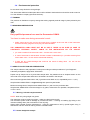
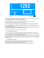
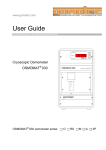
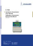
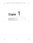
n OSMOMETER OSM-9 User’s manual PLEASE READ THIS MANUAL CAREFULLY BEFORE OPERATION 3, Hagavish st. Israel 58817 Tel: 972 3 5595252, Fax: 972 3 5594529 [email protected] MRC.VER.01-2.14 CONTENT 1 . INTRODUCTION 2 . MEASURING PRINCIPLE 3 . SPECIFICATION AND TECHNICAL DATA 3.1 . Specification 3.2 . Technical data 3.3 . Packaging, storage, transport 3.4 . Environmental protection 4 . TRAINING 5 . MEASURING PREPARATION 6 . SAMPLE COLLECTION AND PREPARATION 6.1 . Warning: infected sample treatment 6.2 . Human bodyfluids treatment 7 . MEASURING HEAD 7.1 . MEASURING HEAD OPERATION 8 . Switch on the OSMOMETER OSM-9 8.1 . Calibration 9 . MEASUREMENTS 9.1 . Measurements 9.2 . Stop during measurements 9.3 . Measurements finishing 10 . Operation note 10.1 . Liquid dosage 10.2 . OSMO-KRIO sample tubes 10.3 . Calibration and control solution 10.4 . Control/test measurements 10.4.1 . Test of measurement precision 10.4.2 . Test of measurement reproducibility 10.5 . Information and practical hints 10.6 . The stirring wire replacement 4 4 5 5 6 6 7 7 7 7 7 8 8 8 8 9 10 10 11 11 12 12 12 12 12 12 13 13 14 2 11 . DESCRIPTION OF ADDITIONAL OSMOMETER FUNCTION 11.1 . Power on the Osmometer OSM-9 11.2 . Description of additional osmometer function 11.2.1 . CALIBRATION 11.2.2 . MEASUREMENTS 11.2.3 . SETTINGS 11.2.3.1 . MEASUREMENT HISTORY 11.2.3.2 . Header – printout / edition 11.2.3.3 . LANGUAGE 11.2.3.4 . DATE AND TIME 11.2.3.5 . AUTO.PRINTOUT 11.3 . “ZOOM” FRAME 11.4 . Measurement stop 11.5 . Factory settlements restore 14 12 . Measurement results printout 12.1 . Serial transmission parameters 13 . Osmometer service transport 13.1 . Additional information 14 . MEANING OF DISPLAYED ANNOUCEMENTS 21 14 14 15 16 17 18 18 19 19 20 20 20 20 21 21 21 21 22 3 1. INTRODUCTION The OSMOMETER OSM-9 is a compact micro processor controlled analyzer for easy and precise osmolality tests in samples of serum, plasma, urine or other body fluids. The OSMOMETER OSM-9 makes the running of the osmolality test very easy. a) 100 μl of the sample are pipetted into a sample tube b) The sample tube is attached to the measuring head c) The measuring head is pushed down into the cooling chamber d) Now the measuring cycle starts automatically e) When the measuring is terminated, the measuring head returns to its upper position again, and the result is digitally displayed in mOsm/kgH2O The 1-point-calibration requires distilled water only, and is one of the most practical features of this analyzer. The calibration values are automatically calculated and stored in the microprocessor memory. The microprocessor control and built in electronic components with high long term stability make the OSMOMETER OSM-9 an analyzer of easy application and reliable results. 2. MEASURING PRINCIPLE The osmolality of a solution is a function of the number of particles - molecules and ions of the substances, which are solved in 1 kg of the solvent. The osmotic concentration or osmolality does not depend on the molecular weight of the solved substances. The solved substances influence several physical parameters of the solution and can be measured. For example: If the osmolality increases, the following parameters of the solution will change: - Osmotic Pressure increases - Freezing Temparature decreases - Boiling Temparature increases - Vapour Pressure decreases A very significant method to measure the osmolality in biological liquids is the detection of the freezing point of the solution. The relation of freezing point temperature and osmolality in diluted solutions is a linear function, so that the basic cryometric rule says: The lowering of the freezing point of the solution compared to the freezing point of the pure solvent is proportional to the osmolality of the solution. The proportional coefficient - called the cryometric constant K - for water is 1,858deg x kgH2O/Osm. During the measuring process the sample is continuously cooled down from ambient to the super cool temperature of -7°C - still being liquid. Then the crystallisation is initiated and the temparature now raises to a maximum, which equals to the freezing point, corresponding to the osmolality of the sample. The typical sample temperature course during the measuring cycle shows fig. below. 4 O C tk t (Min.) 2 1 READY i ti - temperature at which the crystallization in the super cooled solution is initiated tk- lowering of the freezing temp. of the solution according to the osmolality The general equation of tk to osmolality is influenced by several nonlinear functions of the electronic and mechanical components of the analyzer. These values are calculated during the factory calibration and stored in the microprocessor memory in Osmometer OSM-9. 3. SPECIFICATION AND TECHNICAL DATA After having recieved your new OSMOMETER OSM-9, please check the content. Any claims should be reported to your local dealer or to the manufacturer. 3.1. Specification SPECIFICATION Osmometer OSM-9 Sample tubes OSMO-KRIO Calibration solution 0 mOsm/kgH2O Control solution 400 mOsm/kgH2O Stirring wire Cable Fuse User Manual 1pcs 500 pcs 50 ml 5 amp 1 pcs 1 pcs 1 pcs 1 pcs 5 3.2. Technical data TECHNICAL DATA calibration cooling sample volume measuring range resolution precision reproducibility temperature in cooling chamber temperature crystalization initiation measuring time warm up time single point: 0 mOsm/kgH2O thermoelectric (Peltier efect) 100 l 0÷2000 mOsm/kgH2O 1 mOsm/kgH2O +/- 0.5% better as 0.5% - 12.00 oC - 7.00 oC ca. 1.5 min 5 min Power supply : 220V (+10%/-15%), 50-60 Hz, 50 VA Power switch and fuse are located on back side of the instrument. Fuse WTAT500mA/250V Port: RS 232 to printer or PC Ambient temperature: +10oC ÷ + 35oC Storage temperature: - 10oC ÷ + 50oC Relative humidity: 30 ÷ 75% Atm.pressure: 700 ÷ 1060 hPa Storage rel.humidity: 65% Dimensions: 300x200x170/ 290 mm Weight : 6 kg 3.3. PACKAGING, STORAGE AND TRANSPORT The box package, packing condition, storage and transport, it should be according to PN-EN 60601-1:1999 : p.10.1, p. 6.8.3d , p. 3, p.6.1 v, and ISO R 780. Unit box Osmometer’s package should be according to second group division of medical instrument packages. Label information: manufacturer data and instrument type. Production data and symbols regards proper transport position and storage. Collective box 4 pcs osmometers in collective box should be placed without loose in collective box that is made from fivelayer cardboard in one layer. Storage Osmometers in unit box or collective box should be storage in clean and well ventilated room, temperature from -10°C to +50°C and relative humidity not over 65%. Maximum storage time is 1 year. After that time the osmometr have to be validated by special test in authorized service. Transport Ambient condition should be as below during the transport: - temperature -10°C ÷ +50°C - humidity < 85% Reclimatisation after transport should be done with power OFF the Osmometer, in indication work conditions according to p.1.2 this standard, through minimum 3 hours – there should be no moisture at the Osmometer. 6 3.4 . Environmental protection Do not throw away this device as a garbage. The Osmometer OSM-9 includes parts that could be utilized. Useless devices should be send to service or to the utilization company (electronic devices). 4. TRAINING The producer or distributor company arrange the training regards practical usage in place pointed by the user. 5. MEASURING PREPARATION Only qualified personnel can use the Osmometer OSM-9. You have to make sure during osmometer’s work: Cable output have to be put into the output that is located at the rear side of the instrument. It’s earth continuity plug have to be plug into 230V/50-60Hz. THE OSMOMETER OSM-9 MUST NOT BE IN USE IF THERE IS NO SURE IN CASE OF CONTINUITY EXTERNAL SAFETY CABLE IN THE INSTALATION OR IT’S CIRCUIT. you must not take off the osmometr case – it threats with current stroke in case of osmometr is wet because of water or steam condensation (f.e. just after removing from cold to warm room - do not use the Osmometer OSM-9); if there are any visible damage that could be the result of falling down - do not use the Osmometer OSM-9; 6. SAMPLE COLLECTION AND PREPARATION The sample collection and preparation is always according to inside procedures of your Diagnostic Laboratory and please, apply below information. Pipette 100 μl sample into a dry and clean sample tube. Pay attention that no droplets remain on the inner side of the sample tube and that no air bubble is enclosed in the sample. We recommend pipette fixed-volume 100 l (precision error MAX 0,9%; repeatability error 0,4%). Sample tubes OSMO-KRIO is single use only with special crystal seeds. Maximum storage time of sample tubes OSMO-KRIO is 1 year from the purchase date. Sample tube OSMO-KRIO could be storage in dry place, without the sun operation, temperature from 10°C to +40°C. 6.1. Warning: infected sample treatment NOTE!: Work only using single use gloves The thermistor probe is made from glass – make sure that is always safe. The thermistor probe could be damage by mechanical action – cracking or breaking (by hitting or the instrument falling down) that could effect in user injuring. Always after infected sample measurement - rinse the measurement unit by special agent using in disinfection and then rinse all with big amount of distilled water. 6.2. Human bodyfluids sample 7 NOTE!: Work with human bodyfluids sample only using single use gloves. 7. MEASURING HEAD Osmometer OSM-9 – measuring head 7.1. MEASURING HEAD OPERATION The sample tube OSMO-KRIO is carefully moved from below onto the mandrel (1) until the retaining spring (4) engages. The thermistor probe (2) entering the sample tube and the stirring wire (3) must not get damaged while positioning the sample tube and should not be touched, when sample tubes are attached or removed. The measuring head is lowered into the cooling chamber by applying pressure to the pressure point (N). The measuring head is mounted on the slide bar (5) as it is being lowered. The measuring head is then held in bottom position electromagnetically. The electromagnet is ON only after go into MEASUREMENTS or CALIBRATION or SERVICE INFORMATION. 8. Switch on the OSMOMETER OSM-9 !!! Before power ON the Osmometer OSM-9 always dry the cooling chamber by lintless tissue. Power ON the instrument using switch located on back side of the instrument. Wait 5 min. as measuring head will be ready. The display will show the passing time as soon as the cooling chamber reaches work temperature. 2 0 1 1 . 0 6 . 3 0 2 3 : 5 9 : 5 9 O SMOME T E R S L AME D Gmb H * G E RMAN Y V E R : 8 0 0 G 1 1 0 7 0 1 : 2 0 MOD E Fig. 1 Active key: MODE CALIBRATION – READY FOR CALIBRATION inform that Omometer OSM-9 is in calibration mode. 8 C A L I B R A T I ON R E AD Y F OR C A L I B R A T I ON MOD E Fig. 4.2 Active key: MODE Rinse the thermistor probe and stirring wire using distilled water. Dried very carefully thermistor probe and stirring wire to avoid damage or deformation and fibers leaving. Then go to calibration according to p.8.1 CALIBRATION. NOTE! Leaving fibers at the thermistor probe could cause sooner crystallization. NOTE! Deformed stirring wire could not initiate the crystallization. 8.1. Calibration The main function of the calibration is to do the correction of measurement block characteristics. The change of these characteristics is on as natural process of thermistor probe “getting older”. Pipette 100 μl calibration solution sample (distilled water) into a dry and clean sample tube OSMO KRIO. Pay attention that no droplets remain on the inner side of the sample tube and that no air bubble is enclosed in the sample. Sample tube OSMO-KRIO with sample inside is carefully moved from below onto the mandrel until the retaining spring engages. The thermistor probe entering the sample tube and the stirring wire must not get damaged while positioning the sample tube and should not be touched, when sample tubes are attached. Pressure to the pressure point (N) and lower the measuring head into the cooling chamber. The measuring head is then held in bottom position electromagnetically and measurement is started with displaying actual sample temperature. T EMP – 0 0 , 0 ˚ C C A L I B R A T I ON 0 0 mO s m / k g H 2 O T I ME - 4 z o om MOD E - 7 Fig. 12.1 Active key: MODE After measurement the measuring head will return to the upper position. The calibration correction is done automatic and then it’s counted and corrected value will be displayed: 0 mOsm/kgH2O. 9 Take off the sample tube carefully- to avoid the thermistor probe and stirring wire damage. Dry the thermistor probe and stirring wire by lintless tissue. The blinking CURSOR BAR, under ZOOM frame, points sample defrosting. Do not take off the sample tube from measuring head – in case not to damage the thermistor probe. NOTE! When the power is switched off, the memory will lose the calibration value! So every time when the osmometer is switched on, it requires a new calibration to compensate for the long term drift of the thermistor probe parameters. 9. MEASUREMENTS 9.1. Measurements Just after calibration, the Osmometer OSM-9 automatically goes to mode: MEASUREMENTS, READY FOR SAMPLE. ME A S U R EME N T S R E AD Y F OR S AMP L E MOD E Fig. 3.2 Active key: MODE Pipette 100 μl sample into a dry and clean sample tube OSMO KRIO. Pay attention that no droplets remain on the inner side of the sample tube and that no air bubble is enclosed in the sample. Sample tube OSMO-KRIO with sample inside is carefully moved from below onto the mandrel until the retaining spring engages. The thermistor probe entering the sample tube and the stirring wire must not get damaged while positioning the sample tube and should not be touched, when sample tubes are attached. Pressure to the pressure point (N) and lower the measuring head into the cooling chamber. The measuring head is then held in bottom position electromagnetically and measurement is started with displaying actual sample temperature. Just after measurement the measuring head will return to its upper position and the measurement result is displayed. The result is now in MEASUREMENTS HISTORY memory. The displayed temperature is a freezing temperature of sample. The result is displayed continuously to the beginning of the next measurement. The blinking CURSOR BAR, under ZOOM frame, points sample defrosting. Do not take off the sample tube from measuring head – in case not to damage the thermistor probe. 10 T EM P – 0 2 , 4 ˚ C 0 1 292 mOs m / k g H 2 O T I ME - 4 z o om MOD E - 7 Fig. 12 Active key: MODE In case of itself freezing before achieving -7°C temperature, the osmometer makes the measurement result correction that take into account earlier crystallization. THIS CORRECTION IS ON – AT MIN. -4°C SAMPLE FREEZING. Take off the sample tube carefully- to avoid the thermistor probe and stirring wire damage. Rinse the thermistor probe and stirring wire using distilled water. Dried very carefully thermistor probe, stirring wire to avoid damage or deformation and fibers leaving. See point: MEANING OF DISPLAYED ANNOUCEMENTS if at the display appear E - ... The measurement result with an terror signalisation is not in memory. Go to the next measurement without any additional action. The sample tube with sample put on the thermistor probe and stirring wire assembly. Put the sample tube into the cooling chamber by pushing the measurement head. Please, follow above instruction to execute next measurements. 9.2. Stop during measurments You don’t have to power off the Osmometer OSM-9 if the break in measurements in not over 90min. Put a clean sample tube on cleaned and dried thermistor probe and stirring wire. The second one put into the cooling chamber – it makes the frosting process slower. NOTE! You have to power off the Osmometer OSM-9 if the cooling chamber is strong frosted (the symptom is getting stuck of sample tube inside the cooling chamber). Then you have to wait as the frost will melt and dry the cooling chamber with lintless tissue. Just after that action go to p. MEASURING PREPARATION. 9.3. Measurements finishing After finishing all measurements, power off the Osmometer OSM-9 with power switch. Clean the thermistor probe and the stirring wire with distilled water and dry carefully. Empty sample tube put on the thermistor probe and stirring wire. Dry a defrosted cooling chamber with lintless tissue and put into the empty sample tube. 11 10. OPERATION NOTE 10.1. Liquid dosage We recommend pipette fixed-volume 100 l (precision error MAX 0,9%; repeatability error 0,4%). 10.2. OSMO-KRIO sample tubes Sample tube OSMO-KRIO is single use only with special crystal seeds. Maximum storage time of sample tubes OSMO-KRIO is 1 year from the purchase date. Sample tube OSMO-KRIO could be storage in dry place, without the sun operation, temperature from 10°C to +40°C. 10.3. Calibration and control solution Calibration solution 0 mOsm/kgH2O – distilled water APPLICATION see point. 8.1. Control solution 400 mOsm/kgH2O (osmolality standard) is a compound of distilled water and NaCl that has fixed osmolality. The amount of NaCl is 12.687g NaCl/kgH2O and is used to Osmometer OSM-9 measurements control. 10.4. Control/test measurements Introduce with pipette the 100ul control solution 400mOsm/kgH2O sample to the clean and dry sample tube. During pipetting: - avoid making air bubble - do not spill the sample at the sample tube wall Then go to the p. MEASUREMENTS 9.1. The 400mOsm/kgH2O control solution is available in single use ampoules. After ampoules opening and making control measurements cycle – do not store the rest of control solution. THE CONTROL SOLUTION IN OPEN AMPOULES WILL CHANGE IT’S OSMOLALITY WITH TIME AND YOU MUST NOT USE IT AS OSMOLALITY STANDARD. 10.4.1 . Test of measurement precision Test of measurement precision you should according to below information. Do 3 calibration test measurements according to p.5 MEASURING PREPARATION after power ON the Osmometer OSM-9. Use the calibration solution 0 mOsm/kgH2O – acceptable border error ±1 mOsm/kgH2O. If this condition is not fulfill – you must repeat measurement. Next do the series of 10 control solution measurements ( control solution with known osmolality value that is settled in reference method). You could count the osmometr precision error on the base of achieved results: D [%] = (VS - VN ) / VN x 100% VS – mathematic average value from achieved series result VN – expected value – nominal value of using osmolality standard The precision should be no worse than ±0,5%. 12 10.4.2 . Test of measurement reproducibility Test of measurement reproducibility should be done as below: You could count the reproducibility error on the base of measurement results achieved in 10 measurement series according to p.9. P [%] = SD / VS X 100% SD – square standard deviation from the series of achieved results SD V V / n 1 2 1 S VI – next value of achieved measurement result VS – mathematic average value from achieved series result n - the number of measurements in series The reproducibility should be better then ±0,5%. 10.5. Information and practical hints Keep the cooling chamber dry. Especially dry the cooling chamber before you switch on the analyzer so that residual water cannot freeze and interrupt the measurement. After having measured all samples and defrosted the cooling chamber, it have to be always dried by lintless tissue. After having measured all samples switch off the power. Then rinse the thermistor probe and the stirring wire with distilled water and dry both of them carefully. Empty sample tube attached on the rim of the thermistor probe (during pause in measurements or after measurements) make the thermistor probe and stirring wire safer. Additional there is lower possibility of incidental damage. The empty sample tube, inserted into the cooling chamber, protect the cooling chamber against contamination that makes measurement impossible to execute. During the measuring cycles a thin layer of hoar-frost covers normally the cooling chamber. If this layer begins to turn into ice, it could jam the sample tube. In this case the osmometer has to be switched off for defrosting and after that it should be cleaned with lintless tissue. Preparing the Osmometer OSM-9 to work is then according to point 5. MEASURING PREPARATION. The empty sample tube inserted into the cooling chamber, during measurements pause, will make chamber frosting much more slower. After long break in instrument work we recommend before measurement to rinse the thermistor probe and stirring wire with distilled water and dry with lintless tissue. In case runner contamination that could be observed Contamination of slide bar. Signs: slow or not full upwards movement of measurement head. Action: clean the slide bar with alcohol and clean contamination with lintless tissue. Repeat it several times to the moment of achieving smooth in measurement head movement. The slide bar cleaning ONLY with power off the Osmometer OSM-9. Osmometer cleaning. Power OFF the Osmometer OSM-9 before any clearing action. Clean the osmometer case with smooth and wet cloth. Do not use any organic solvents. You can use soft detergent to remove of strong contamination and then clean it with wet cloth and dry. 13 10.6. The stirring wire replacement The problem with sample freezing could be a result of stirring wire deformation. Stirring wire changing: unscrew the stirring wire screw with fingers and remove deformed stirring wire from the measurement head. Mount a new stirring wire at the axis screw in such way that after it’s mounting in the measurement head the bending end of stirring wire is in the direction of the thermistor probe. 11. DESCRIPTION OF ADDITIONAL OSMOMETER FUNCTION 11.1. POWER ON THE OSMOMETER OSM-9 The information regards model, manufacturer or instrument version will appear just after power ON the instrument [Fig.1]. The actual data and time will appear at the top of the display. The user could observe passing time at the display. It is time that the Osmometer OSM-9 needs to be ready to work. 2 0 1 1 . 0 6 . 3 0 2 3 : 5 9 : 5 9 O SMOME T E R S L AME D Gmb H * G E RMAN Y V E R : 8 0 0 G 1 1 0 7 0 1 : 2 0 MOD E Fig. 1 Active key: MODE 11.2 . DESCRIPTION OF ADDITIONAL OSMOMETER FUNCTION. You can use MODE mode. By pressing from menu. key during instrument preparation to measurements as well as to normal work MODE you can go to MAIN MENU [Fig.2]. By keys you can choose points 1 . ME A S U R EME N T S 2 . C A L I B R A T I ON 3 . S E T T I NG S 4 . S E R V I C E 0 1 : 4 0 MOD E Fig. 2 Active key: MODE 14 11.2.1 . CALIBRATION From MAIN MENU you can go to CALIBRATION mode. The osmometr will display the preparation time if the cooling chamber is not ready [Fig.4]. C A L I B R A T I ON 0 1 : 4 0 MOD E Fig. 4 Active keys: MODE Using MODE during cooling chamber preparation, go to MAIN MENU. As soon as the cooling chamber is ready to work, the osmometer displays CALIBRATION - READY FOR CALIBRATION [Fig.4.2]. Calibration activities are according to p.8.1. C A L I B R A T I ON R E AD Y F OR C A L I B R A T I ON MOD E Fig. 4.2 MODE Active keys: MODE go to the MAIN MENU. 11.2.2 . MEASUREMENTS 15 From MAIN MENU you can go to MEASUREMENTS mode. The osmometr will display the preparation time if the cooling chamber is not ready [Fig.3], after that device go to CALIBRATION mode [Fig.4.2]. ME A S U R EME N T S 0 1 : 4 0 MOD E Fig. 3 Using MODE Active keys: MODE during cooling chamber preparation, go to MAIN MENU. As soon as the cooling chamber is ready to work, the osmometer displays MEASUREMENTS - READY FOR SAMPLE [Fig.3.2]. Measurement activities are according to p.9.1. ME A S U R EME N T S R E AD Y F OR S AMP L E MOD E Fig. 3.2 MODE Active keys: MODE go to MAIN MENU. 11.2.3. SETTINGS 16 SETTING mode in MAIN MENU go to SETTING menu [Fig.5]. SETTING possibilities: - review / printout / deleting measurement history [Fig.6] - language change [Fig.7] - date and time setting [Fig.8] - ON /OFF automatic printout after measurement [Fig.9] S E T T I NGS 1 . M E A S U R EM E N T S R E V I EW 2 . L A NG U AG E 3 . D A T E & 4 . A U T O . T I M E P R I N T OU T 5 . R E T U R N MO D E Fig. 5 Active keys: MODE 11.2.3.1 MEASUREMENTS REVIEW Option in MEASUREMENTS REVIEW [Fig.6]: - header print print all delete delete all - printout/edition - printout single result signed by the cursor - printout all results from memory with header - delete single result signed by the cursor - delete all measurement history ME A S U R EME N T S R E V I EW d e l e t e a l l ▲ 0 0 0 0 – – – – – – 1 2 3 4 – – – – – – mO k . 0 . 0 . 0 . 1 . – . – . – . – . – . – s g 8 2 4 6 – – – – – – m H 0 8 0 0 – – – – – – \ 2 O 1 1 7 : 5 3 7 1 8 : 0 0 0 1 8 : 1 2 0 1 8 : 2 0 – – – : – – – – – : – – – – – : – – – – – : – – – – – : – – – – – : – – ◄ ► ▼ 1 1 1 1 – – – – – – 6 6 6 6 – – – – – – . . . . . . . . . . 0 0 0 0 – – – – – – 5 5 5 5 – – – – – – . . . . . . . . . . 2 2 2 2 – – – – – – 0 0 0 0 – – – – – – 1 1 1 1 – – – – – – 1 1 1 1 – – – – – – d e l e t e p r i n t a l l p r i n t h e a d e r r e t u r n MOD E Fig. 6 Move the cursor at the chosen result by - move cursor at the option Active keys: MODE (max 99 results in memory). MODE - accept of the option choice - return to the measurement result list The cursor returns to the measurement list just after deleting chosen result. The results will automatically are in new order without deleted result. 11.2.3.2. Header - printout / edition 17 H E AD E R - O SMOME T E R - 0 0 1 1 S E R : N o . OG - - - - - - - - - - - - - A B C D E F GH I J K L - - - - - - - - - - - - - e d i t p r i n t r e t u r n MOD E Fig. 14 Active keys: MODE Possibilities in HEADER mode in MEASUREMENTS REVIEW: - the changing the second part of the header (38 signs) - choose - the cursor will go under one of letter from edited text - by „edit” option and confirm by MODE - choosing from letter available in signs table: 0123456789 * / – . [space bar] ABCDEFGHIJKLMNOPQRSTUWXYZ Move the cursor by using MODE or and chose the next letter to edit. The finished text is confirmed by . Option „print” – header single printo ntout ut Option „return” – return to MEASUREMENTS REVIEW 11.2.3.3 LANGUAGE The T he language is selected by using MODE and confirmed by key. S E T T I NG S 1 . M E A S U R EM E N T S R E V I EW 2 . L A NG U AG E 3 . D A T E & 4 . A U T O . T I M E E D P F N E O R G U L A L T S N I S K Ç S H C H I A I S P R I N T O U T 5 . R E T U R N MO D E Fig. 7 Active key: MODE 11.2.3.4 . DATE AND TIME 18 In date and time settlement keys minute. keys change their value. move the arrow pointer between year, month, day, hour, The date is settled in the order: year, month, day. When settled minutes, seconds are reset. The confirmation is done by MODE key. S E T T I NGS 1 . M E A S U R EM E N T S R E V I EW 2 . L A NG U AG E 3 . D A T E & 4 . A U T O . T I M E 2 0 1 1 . 1 2 . 3 1 P R I N T OU T 1 7 : 5 3 5 . R E T U R N MO D E Fig. 9 Active keys: MODE 11.2.3.5 . AUTO. PRINTOUT SETTINGS – AUTO.PRINTOUT decided if each measurement is printed. ON – printout after measurement OFF – no printout after measurement The results with error or negative are not printed. . The printout state are changed with using S E T T I NGS 1 . ME AS UR EME N T S R E V I EW 2 . L ANGUAG E 3 . DA T E & 4 . AU T O . T I ME P R I N T OU T – ON 5 . R E T URN MOD E Fig. 9 Active keys: MODE 11.3. „ZOOM” FRAME The graph in „zoom” frame [Fig.12] shows the sample temperature after crystallization induction in time of max temperature reaching. 19 1 pixel is 0,001˚C in vertical axis. There is no mistake if the graph is outside the “zoom” frame. It could happen if the sample crystallization is slow. 11.4. MEASUREMENT STOP Pushing MODE in any moment of measurement or calibration will stop actual activity [Fig.11]. The sample could need time to defrosted - the signalization is blinking cursor (it depends on the measurement stage). DO NOT TAKE OFF THE SAMPLE TUBE FROM MEASURING HEAD, IN CASE NOT TO DAMAGE THE THERMISTOR PROBE. T EMP + 0 0 , 0 ˚ C * * * S T O P * * * 0 T I ME - 4 MOD E - 7 Fig. 11 Active keys: MODE The keyboard is not active to the time of sample defrosting. You can continue measurements from the moment of reaching by the sample temperature over zero or with using MODE return to MAIN MENU. 11.5. Factory settlements restore before power ON the osmometer. To restore the factory settlements – press Then power ON the osmometer with still pressing key. NOTE: Remember to make an actual date and hour. 12. MEASUREMENT RESULTS PRINTOUT To printout measurement results, connect printer output RS232 to the Osmometer OSM-9 output RS232 from the rear side of the instrument. Do the Osmometer OSM-9 and the printer connection without any power supply. Do the connection in the order: first Osmometer OSM-900 then the printer. The printout is made after each measurement automatically. NOTE! Connected printer to the Osmometer OSM-9 has to be used to printing. You do not use the printer – disconnect it from the Osmometer OSM-9. The printer cooperates with the Osmometer OSM-9: - RS 232 (serial transmission) - graphical mode work - cable 9-pin cannon input (rear side of the osmometer) 20 12.1. Serial transmission parameters speed : format: even bit: stop bit 2400 bod 8 bits without even bit 1 Active signal TX, DTR 13. Osmometer service transport The instrument have to be disinfected before service transport! Service contact – give an information available in SERVICE INFORMATION – p.4 MAIN MENU. S E R V I C E S E R I A L N UMB E R : OG - 0 0 1 1 V L A D O I N I L N A G T AG E E AC L OG I T A L C A L I B R A T I ON T 1 0 0 K : 2 3 2 5 0 T O : 2 2 7 1 4 : : 2 3 1 , 0 V : 1 2 , 1 V : 5 , 0 V T H E RM I S T OR D A T A : A 1 : 6 9 0 0 A 2 : - 1 5 1 COO L I NG C H AMB E R : T EMP . : - 1 1 , 9 ˚ C C U R R E N T : 1 , 2 5 A T EMP . : S T I R R I NG W I R E E L E C T ROMAGN E T I N F O . 2 0 ˚ C : O F F : Fig. 13 ▼ ▲ MOD E Active key: MODE Efficiency stirring wire test – by short pressing of key. Electromagnet test operation – put the empty sample tube ant the measuring head and insert it in cooling chamber (see p.7.1). key will release the measuring head. MODE key return to the MAIN MENU. 13.1. Addition information The manufacturer has rights to introduce changes and make a modernization of the osmometer during production cycle. 14. MEANING OF DISPLAYED ANNOUCEMENTS The control programme controls the Osmometer OSM-9 work and every measurement procedure. All defects are signalized by E- … (proper number) that are displayed in top of the screen. CODE MEANING DEFECT REASON DEFECT REMOVING 21 E- 91 thermistor probe damage E- 01 E- 92 not proper cooling chamber temperature E- 02 E- 93 E- 03 E- 04 E- 94 problems durig sample crystalization measurment head does not go out from the cooling chamber SERVICE warming up the cooling chamber remove warm source, and after 30 sec. put MODE defect of cooling circuit SERVICE próbka zbyt stężona over measurement limits (> 2000 mOsm/kg H2O) deformation of stirring wire stirring wire assembly damage defect of the termistor probe the lack of crystal seeds stirring wire change SERVICE SERVICE repeat the measurement in the new sample tube sample tube binding in defrost and dry the cooling the cooling chamber chamber upper mechanism defect SERVICE contamination of clean the slide bar measuring head runner wrong calibration sample use distilled water not acceptable calibration measurement result the measurement head contamination of does not do up and is measuring head runner over the cooling chamber clean the slide bar and mandrel with alcohol acc. p 10.5 User’s Manual E - 0 1 T EM P + 2 0 , 0 ˚ C 0 T I ME - 4 MOD E - 7 Fig. 10 Active key: MODE 22